 Every three years, the National Electrical Code® (NEC®) is revised and expanded. Initially the NFPA® received 4,006 public suggestions for changes, which resulted in 1,805 first revisions. There were 1,956 public comments submitted in response to these 1,805 first revisions, resulting in 900 second revisions. Changes included editorial clarification, expanded requirements, new requirements, deleted requirements, and the relocation of other requirements.
What to Expect
In this course the student will be presented an overview of the most significant changes found in the 2023 NEC. This is part 1 of a series of courses covering the changes and will progress through each chapter and its articles presenting the many important changes. The changes will be underlined for easy recognition and a short synopsis of the reason for the change is presented as well.
Disclaimer
Although every effort has been made to the accuracy of the material presented, by no means shall the student use or substitute this material for official 2023 NEC. Additionally, Ezekiel Enterprises, LLC shall not be liable for any special, incidental, consequential, or exemplary damages resulting, in whole or in part, from the reader’s uses of or reliance upon this material.
Revision – 500.4
Documentation
■ What Changed: Additional language added in Section 500.4 to assist the authority having jurisdiction (AHJ) for requirements on documentation for hazardous (classified) locations. The parent text of 500.4 was revised to require that the documentation provided includes an area classification drawing. The change will create a consistent method of documenting hazardous (classified) locations and clearly indicate the boundaries between the classified areas and unclassified areas.
■ Its Effect: This new language allows the AHJ to require the designers to provide additional information on the plans for the installations and inspections in the field to verify code compliance with the NEC. This new language will assist the electrical plans examiner, inspector, and installer to verify that the installation meets Code requirements for all hazardous (classified) locations.
(A) Voltage.
All areas Areas designated as hazardous (classified) locations or determined to be unclassified shall be properly documented, on an area classification drawing and other associated documentation. This documentation shall be available to the authority having jurisdiction (AHJ) and those authorized to design, install, inspect, maintain, or operate electrical equipment at the location.
Informational Note No. 1: See the following standards for additional information on the classification of locations:
NFPA 30-2021, Flammable and Combustible Liquids Code
NFPA 32-2016, Standard for Drycleaning Facilities
NFPA 33-2021, Standard for Spray Application Using Flammable or Combustible Materials
NFPA 34-2021, Standard for Dipping, Coating, and Printing Processes Using Flammable or Combustible Liquids
NFPA 35-2021, Standard for the Manufacture of Organic Coatings
NFPA 36-2021, Standard for Solvent Extraction Plants
NFPA 45-2019, Standard on Fire Protection for Laboratories Using Chemicals
NFPA 55-2020, Compressed Gases and Cryogenic Fluids Code
NFPA 58-2020, Liquefied Petroleum Gas Code
NFPA 59-2021, Utility LP-Gas Plant Code
NFPA 497-2021, Recommended Practice for the Classification of Flammable Liquids, Gases, or Vapors and of Hazardous (Classified) Locations for Electrical Installations in Chemical Process Areas
NFPA 499-2021, Recommended Practice for the Classification of Combustible Dusts and of Hazardous (Classified) Locations for Electrical Installations in Chemical Process Areas
NFPA 820-2020, Standard for Fire Protection in Wastewater Treatment and Collection Facilities
ANSI/API RP 500-2012, Recommended Practice for Classification of Locations for Electrical Installations at Petroleum Facilities Classified as Class I, Division 1 and Division 2
ISA-12.10-1988, Area Classification in Hazardous (Classified) Dust Locations
Revision – 500.5(D)(1)(a)
Combustible Fibers/Flyings
■ What Changed: The previous Code language at 500.5(D)(1)(a) has been completely reworded to align with the new definition for combustible fibers/flyings and the edits for combustible dust.
■ Its Effect: The new language and definitions will help the industry determine the type of hazardous (classified) locations that exist. The consistency in language for all the NFPA standards for the new definitions will assist all electrical professionals who design, install, and inspect in these environments.
(a) Combustible Fibers/Flyings. Locations where nonmetal combustible fibers/flyings are in the air under normal operating conditions in quantities sufficient to produce explosible mixtures or where mechanical failure or abnormal operation of machinery or equipment might cause combustible fibers/flyings to be produced and might also provide a source of ignition through simultaneous failure of electrical equipment, through operation of protection devices, or from other causes shall be classified as Class III, Division 1. Locations where metal combustible fibers/flyings are present shall be classified as Class II, Division 1, Group E.
Informational Note No. 1: Such locations usually include some parts of rayon, cotton, and other textile mills; associated manufacturing and processing plants; cotton gins and cotton-seed mills; flax-processing plants; clothing manufacturing plants; woodworking plants; and establishments and industries involving similar hazardous processes or conditions.
Informational Note No. 2: Combustible fibers/flyings include flat platelet-shaped particulates, such as metal flakes, and fibrous board, such as particle board.
Revision – 500.8(D)(2) and (3)
Equipment, Temperature, Class II and Class III
■ What Changed: The previous language for 500.8(D)(2) and (3) that involve Class II and Class III temperature has been edited and revised to align with the new definition for combustible fibers/flyings.
■ Its Effect: The edits to 500.8(D)(2) and (D)(3) and the new definition will help the industry to determine the type of equipment permitted in these locations. This change provides consistency in language and requirements for all electrical professionals who design, install, and inspect.
(D) Temperature.
(1) Class I Temperature.
The temperature marking specified in 500.8(C) shall not exceed the autoignition temperature of the specific gas or vapor to be encountered.
Informational Note: See NFPA 497-2021, Recommended Practice for the Classification of Flammable Liquids, Gases, or Vapors and of Hazardous (Classified) Locations for Electrical Installations in Chemical Process Areas, for information on autoignition temperatures of gases and vapors.
(2) Class II Temperature.
The temperature marking specified in 500.8(C) shall be less than the ignition temperature of the specific dust or metal fiber/flying to be encountered. For organic dusts that may might dehydrate or carbonize, the temperature marking shall not exceed the lower of either the ignition temperature or 165°C (329°F).
Informational Note: See NFPA 499-2021, Recommended Practice for the Classification of Combustible Dusts and of Hazardous (Classified) Locations for Electrical Installations in Chemical Process Areas, for minimum ignition temperatures of specific dusts.
(3) Class III Temperature.
The temperature marking specified in 500.8(C) shall be less than the ignition temperature of the specific fiber/flying to be encountered, except as specified in 500.8(D)(3)(a) or (D)(3)(b).
For nonmetal combustible fibers/flyings that might dehydrate or carbonize, the temperature marking shall not exceed the lower of either the ignition temperature or 165°C (329°F).
When ignitable fibers/flyings are present, the maximum surface temperatures under operating conditions shall not exceed 165°C (329°F) for equipment that is not subject to overloading, and 120°C (248°F) for equipment (such as motors or power transformers) that might be overloaded.
New – 505.9(C) Chapter 9 Table 13
Equipment Suitable for Hazardous (Classified) Locations
■ What Changed: A new Table 13 was created in Chapter 9 entitled Equipment Suitable for Hazardous (Classified) Locations. The text was deleted at 505.9(C)(2)(4) referencing Table 505.9(C)(2)(4) with new text added to reference Chapter 9 Table 13. The new Table 13 in Chapter 9 provides a complete list of the types of protection for hazardous (classified) locations and improves the readability of 505.9(C)(2) (4).
■ Its Effect: This new table will assist the electrical industry by providing an improved list of equipment suitable for various locations. The new table and revisions will assist the designer, contractors, and the AHJ in verifying compliance with the Code and the manufacturer’s listing of the equipment installed in a hazardous (classified) location for both zone and other classified locations.
(2) Zone Equipment.
Equipment meeting one or more of the protection techniques described in 505.8 shall be marked with all of the following in the order shown:
- Class I (equipment shall be permitted to omit the Class I marking)shall be an optional marking. If it is included in the equipment marking, the Class I marking shall precede the zone marking.
- Zone in accordance with Table 505.9(C)(2)(4)Chapter 9, Table 13.
New – Article 512
Cannabis Oil Equipment and Cannabis Oil Systems Using Flammable Materials
■ What Changed: New Article 512 was created to cover cannabis oil extraction equipment, booths, postprocessing equipment, and systems using flammable materials in commercial and industrial facilities. This is a new and expanding industry, and Article 512 is intended to address the hazards associated with the extraction of cannabis oil. This is in response to concerns raised by authorities having jurisdiction (AHJ) and other industry members regarding fire and explosion hazards associated with equipment used to process and extract plant oils from cannabis.
■ Its Effect: The cannabis industry has its own unique set of issues that require designers, contractors, and inspectors to become familiar with the new extraction and processing technologies. Flammable solvents such as butane, pentane, hexane, propane, and ethanol can be released during the processing and extraction of plant oils. This may also include high temperatures and high pressures, which increase the risk of fire and explosion.
Article 512 Cannabis Oil Equipment and Cannabis Oil Systems Using Flammable Materials
Part I. General
512.1 Scope.
This article covers cannabis oil preparatory equipment, extraction equipment, booths, post-processing equipment, and systems using flammable materials (flammable gas, flammable liquid–produced vapor, combustible liquid–produced vapor) in commercial and industrial facilities.
Note: See NEC for Complete Text
Revision – 515.10
Special Equipment – Motor Fuel Dispensers
■ What Changed: The title of Section 515.10 was changed from “Gasoline Dispensers” to “Motor Fuel Dispensers.” This change was to assist the industry regarding code enforcement for all types of fuel dispensers, regardless of fuel type.
■ Its Effect: The revisions will help the industry understand that this requirement applies to all flammable liquids and liquified flammable gases. This will assist the electrical industry concerning the design, installation, interpretation, and enforcement of the Code.
515.10 Special Equipment — Gasoline Motor Fuel Dispensers.
Where In addition to the requirements of this article, dispensers for gasoline or other volatile flammable liquids or liquefied liquified flammable gases are dispensed at bulk stations, the requirements of 514.1 shall apply shall comply with the requirements for motor fuel dispensing facilities, as applicable, except as modified by this article.
Revision – Article 517
Health Care Facilities
■ What Changed: With the edition of the 2023 NEC, the phased approach has been completed of changing the references found in Article 517 for health care facilities from critical, general, basic, and support spaces to Category 1, 2, 3, and 4 Spaces.
■ Its Effect: This will allow for harmony between the two documents with fewer conflicts between designers and installers/inspectors. Consistent use of the terminology related to patient care and support spaces will bring better useability to the Code. Many users of the NEC are also users of NFPA 99, therefore if the two documents are using the same terminology, the user can better understand the requirements.
Article 517 Health Care Facilities
Part I. General
517.1 Scope.
This article applies to electrical construction and installation criteria in health care facilities that provide services to human beings.
The requirements in Parts II and III not only apply to single-function buildings but are also intended to be individually applied to their respective forms of occupancy within a multifunction building (e.g., a doctor’s examining room located within a limited care facility would be required to meet 517.10).
Note: See NEC for Complete Text
New – 517.6
Patient Care-Related Electrical Equipment
■ What Changed: It has been determined that the reconditioning requirements found elsewhere in the Code do not apply to patient care-related electrical equipment. Patient care-related electrical equipment is different from the other electrical equipment as it will be reconditioned or recertified in accordance with U.S. Federal Food, Drug, and Cosmetic Act (FDCA) when relocated. Health care facilities have used reconditioned equipment for many years without any record of failure, and it is imperative they maintain the ability to do so.
■ Its Effect: This clarification is beneficial to the electrical professional, so they are aware that marking and labeling requirements found at 110.21(A)(2) and other restrictions on the use of reconditioned equipment will not apply to electrical equipment used in patient care-related activities.
517.6 Patient Care–Related Electrical Equipment.
The reconditioning requirements of this Code shall not apply to patient care–related electrical equipment.
Informational Note No. 1: Patient care–related electrical equipment is differentiated from electrical equipment as described in 110.21(A)(2).
Informational Note No. 2: If patient care–related electrical equipment is relocated, it is expected to be recommissioned or recertified in accordance with the U.S. Federal Food, Drug, and Cosmetic Act (FDCA).
Relocation / Revision – 517.13
Equipment Grounding Conductor for Receptacles and Fixed Electrical Equipment in Patient Care Spaces
■ What Changed: Section 517.13 was revised for clarity by relocating former Exception No. 2 to follow the opening paragraph and by stating wiring “serving” patient care spaces. The change was necessary to clarify the connection of the equipment grounding conductor for receptacles and fixed electrical equipment in patient care spaces.
■ Its Effect: The change will provide a clear understanding of the application of the equipment grounding conductor connection requirements for branch circuits serving patient care spaces.
517.13 Equipment Grounding Conductor for Receptacles and Fixed Electrical Equipment in Patient Care Spaces.
Wiring in serving patient care spaces shall comply with the requirements of 517.13(A) and (B).
Exception: Luminaires more than 2.3 m (71⁄2 ft) above the floor and switches located outside of the patient care vicinity shall be permitted to be connected to an equipment grounding return path complying with the requirements of 517.13(A) or (B).
(A) Wiring Methods.
All branch circuits serving patient care spaces shall be provided with an effective ground-fault current path by installation in a metal raceway system or a cable having a metallic armor or sheath assembly. The metal raceway system, metallic cable armor, or sheath assembly shall itself qualify as an equipment grounding conductor in accordance with 250.118.
(B) Insulated Equipment Grounding Conductors and Insulated Equipment Bonding Jumpers.
(1) General.
The following shall be directly connected to an An insulated copper equipment grounding conductor that is clearly identified along its entire length by green insulation and installed with the branch circuit conductors in within the wiring methods as provided in method in accordance with517.13(A) shall be directly connected to the following:
The grounding Grounding terminals of all receptacles other than isolated ground receptacles
Metal outlet boxes, metal device boxes, or metal enclosures
All non Non–current-carrying conductive surfaces of fixed electrical equipment likely to become energized that are subject to personal contact, operating at over 100 volts
Metal faceplates, by means of a metal mounting screw(s) securing the faceplate to a metal yoke or strap of a receptacle or to a metal outlet box
Exception No. 1: For other than isolated ground receptacles, an insulated equipment bonding jumper that directly connects to the equipment grounding conductor is shall be permitted to connect the box and receptacle(s) to the equipment grounding conductor. Isolated ground receptacles shall be connected in accordance with 517.16.
Exception No. 2: Luminaires more than 2.3 m (71⁄2 ft) above the floor and switches located outside of the patient care vicinity shall be permitted to be connected to an equipment grounding return path complying with 517.13(A) or (B)Metal faceplates shall be connected to an effective ground-fault current path by means of a metal mounting screw(s) securing the faceplate to a metal yoke or strap of a receptacle or to a metal outlet box.
New – 517.22
Demand Factors
■ What Changed: It has been determined that the use of demand factors is acceptable and permitted for general-purpose receptacle loads in Category 1, 2, 3, and 4 patient care spaces. Without the ability to apply demand factors to the receptacle load calculations required by Article 220, unnecessarily large feeders to branch circuit panelboards supplying patient care areas resulted. To provide relief to this situation, Section 517.22 was added to provide a reference to Section 220.48, Receptacle Loads – Health Care Facilities,
■ Its Effect: The permitted use of demand factors for calculating loads in patient care areas will provide relief to electrical professionals when sizing feeders to branch circuit panelboards supplying those areas.
517.22 Demand Factors.
Demand factors for receptacle loads supplied by general-use receptacles and individual branch circuits not exceeding 150 volts to ground and installed in Category 1, Category 2, Category 3, and Category 4 patient care spaces shall be permitted to be applied in accordance with 517.22(A) and (B)220.110.
Informational Note: See Article 100 for the definitions of patient care space categories.
Revision – 517.30
Sources of Power
■ What Changed: Revisions were made for consistent use of terminology, to clarify the types of sources of power, and to recognize energy storage systems and health care microgrids in Section 517.30. Revisions were also made to clarify that the essential electrical system (ESS) must have two independent sources: one on-site source (or set of sources) that must be sized to supply the entire EES and another source, permitted to be on-site or off-site, that must also supply the entire EES. Additional sources other than the first two independent sources can be sized for the intended load.
■ Its Effect: The electrical professional will have a clearer understanding of the Energy Storage System (EES) power source requirements and also become aware of the addition of two new sources of power. The newly added sources of power have been proven to be reliable for all types of health care type occupancies along with already accepted types of occupancies.
517.30 Sources of Power.
(A) Two Independent Power Sources.
Essential electrical systems shall have a minimum of the following two independent sources of power: a normal source generally supplying the entire electrical system and one or more alternate sources for use when the normal source is interrupted. [99:6.7.1.1.2]Essential electrical systems (EES) shall have two or more independent sources (or sets of sources). One on-site source (or sets of sources) shall be sized to supply the entire EES. The other independent source (or sets of sources) shall be sized to supply the entire EES and shall be permitted to be located on-site or off-site. Additional sources other than the first two independent sources shall be permitted to be sized to supply the intended load.
Informational Note: An example of a set of sources may be several generators that combined serve the entire EES.
(B) Types of Normal Power Sources.
Normal power sources shall be permitted to be any of the following:
Utility supply power
Generation units
Health care microgrid
Fuel cells
(B) Types of Alternate Power Sources for the EES.
Alternate power Power sources for the EES shall be permitted to be any of those specified in 517.30(B)(1)517.30(C)(1) through (C)(5)(B)(5).
Revision – 517 Part V
Diagnostic Imaging and Treatment Equipment
■ What Changed: The title and applicable text in Article 517 have been changed from “X-Ray Installations” to “Diagnostic Imagining and Treatment Equipment.” The previous language did not adequately distinguish between x-ray equipment and other modalities for diagnostic imagining. More and more non-x-ray diagnostic equipment is becoming the industry norm, so the NEC needed to better define these needs.
■ Its Effect: The title and applicable text were revised to adequately address current industry practices and equipment encountered in these locations. This will make the useability of the NEC better for the user.
Part V. X-Ray Installations Diagnostic Imaging and Therapeutic Equipment Installations
Revision – 518.2
General Classification. (A) Examples.
■ What Changed: Casinos and gaming facilities are now included in the list of assembly occupancy examples.
■ Its Effect: If there was any confusion within the electrical professional community, this addition of these two locations clarifies that Article 518 applies to casinos and gaming facilities. In the past, there has been some confusion of whether or not casinos are considered assembly occupancies in the electrical community as well as the building community.
(A) Examples.
Assembly occupancies shall include, but not be limited to, the following:
- Armories
- Assembly halls
- Auditoriums
- Bowling lanes
- Casinos and gaming facilities
- Club rooms
- Conference rooms
- Courtrooms
- Dance halls
- Dining and drinking facilities
- Exhibition halls
- Gymnasiums
- Mortuary chapels
- Multipurpose rooms
- Museums
- Places of awaiting transportation
- Places of religious worship
- Pool rooms
- Restaurants
- Skating rinks
Revision – 518.4
Wiring Methods
■ What Changed: Section 518.4(A) and the Exception were revised into a list format, and two titled subdivisions and content were added to clarify that Power over Ethernet (PoE) is included. Two titled subdivisions were added, providing clarity and usability. Previously, the reference to Class 2 and 3 circuits in Article 725 was specific to remote control and signaling circuits. Section 518.4(B)(4), Class 2 circuits that transmit power, data, or both to a powered device, was added, making it clear that Power over Ethernet
(PoE) is permitted as a fixed wiring method for that specific application.
■ Its Effect: The reformat of Section 518.4(A) adds clarity and usability to the document. The electrical professional will find this more user-friendly and easier to reference. Changes in technology present changes in the Code or the Code becomes outdated. Not addressing new technologies does not give the Code user any direction. Can also prevent a conflict between inspectors and installers.
518.4(A) General. The wiring method shall qualify as an equipment grounding conductor in accordance with 250.118 or shall contain an equipment grounding conductor sized in accordance with Table 250.122 and shall be any of the following:
(1) Metal raceways
(2) Flexible metal raceways
(3) Nonmetallic raceways encased in not less than 50 mm (2 in.) of concrete
(4) Type MI, Type MC, or Type AC cable
518.4(B) Communications, Signaling Systems, Data Systems, Fire Alarm Systems, and Systems Less Than 120 Volts, Nominal.
Fixed wiring methods for specific installations shall be as follows:
(1) Audio signal processing, amplification, and reproduction equipment — 640.9
(2) Communications systems — Part IV of Article 805 and Part VI of Article 840
(3) Class 2 and Class 3 remote control and signaling circuits — Article 725, Part III
(4) Class 2 circuits that transmit power, data, or both to a powered device
Revision – 518.5
Supply
■ What Changed: The section concerning assembly occupancies was reorganized for clarity and revised, including requirements for commercial appliance outlet centers and panelboard orientation. The reorganizing into a list format with titled subdivisions was necessary, as previously, there were several requirements in a single paragraph. In addition, revisions to specifically reference commercial outlet appliance centers that have unique features such as a panelboard in a face-up position were added. Because the general requirements for panelboard orientation in 408.43 do not permit mounting of panelboards in a face-up position, it was necessary to permit the orientation for listed commercial appliance outlet centers designed for in-floor mounting.
■ Its Effect: The reorganization of this section provides clarity for the electrical professional while recognizing the use of specific equipment. This should enhance the useability of the Code resulting in fewer conflicts between the installer and the AHJ.
518.5 Supply.
Portable switchboards and portable power distribution equipment shall be supplied only from listed power outlets of sufficient voltage and ampere rating. Such power outlets shall be protected by overcurrent devices. Such overcurrent devices and power outlets shall not be accessible to the general public. Provisions for connection of an equipment grounding conductor shall be provided. The neutral conductor of feeders supplying solid-state phase-control, 3-phase, 4-wire dimmer systems shall be considered a current-carrying conductor for purposes of ampacity adjustment. The neutral conductor of feeders supplying solid-state sine-wave, 3-phase, 4-wire dimming systems shall not be considered a current-carrying conductor for purposes of ampacity adjustment.
Portable switchboards, portable power distribution equipment, and commercial appliance outlet centers shall be installed in accordance with 518.5(A) through (C).
Note: See NEC for Complete Text
Revision / Reorganization – Article 530
Motion Picture and Television Studios and Remote Locations
■ What Changed: Article 530 was completely reorganized for clarity and rewritten to remove old technologies and to include dominant and emerging new technologies. The article’s rewrite was the result of the work of a task group with a broad representation from motion picture producers, labor, supply chain, and users. The scope of the article was revised to acknowledge current safe work practices by stating that the requirements of the article apply to motion picture and television studios in facilities and locations staffed by qualified persons. “Locations” was added to the areas covered by the article as production no longer just occurs only in major centers such as Hollywood and New York. It can occur anywhere in the country. The term “location” is defined in Article 100 as a place outside a motion picture studio where a production is filmed or recorded.
■ Its Effect: The changes in Article 530 will provide additional clarity for AHJs and other electrical professionals in locations where motion picture or television work and production was not the norm.
530.1 Scope.
The requirements of this article shall apply to motion picture and television studios and motion picture studios using either film or electronic cameras, in facilities and locations staffed by qualified personnel, except as provided in 520.1., and exchanges, factories, laboratories, stages, or a portion of the building in which film or tape more than 22 mm (7⁄8 in.) in width is exposed, developed, printed, cut, edited, rewound, repaired, or stored. Such occupancies shall include those using either electronic or film cameras for image capture.
Informational Note: For methods of protecting against cellulose nitrate film hazards, see NFPA 40-2019, Standard for the Storage and Handling of Cellulose Nitrate Film See NFPA 40-2019, Standard for the Storage and Handling of Cellulose Nitrate Film, for methods of protecting against cellulose nitrate film hazards.
Note: See NEC for Complete Text
New – 547.26
Physical Protection (Agricultural Buildings)
■ What Changed: A new Section 547.26, Physical Protection, was added to the 2023 NEC as it was determined that nonmetallic cables will be prohibited from being concealed within walls and above ceilings of buildings that are contiguous with or physically adjoin livestock confinement areas. Rodents and other pests have caused damage to wiring systems such as nonmetallic sheathed cables. Therefore, the use of this wiring method concealed in walls and above ceilings is no longer allowed. There is also a requirement that protection is to be provided for all types of electrical wiring that is subject to physical damage.
■ Its Effect: The installer and inspector should be aware that the use of a non-metallic sheathed cable to be concealed in walls or above ceilings in an agricultural building is prohibited.
547.26 Physical Protection.
All electrical wiring and equipment subject to physical damage shall be protected.
Nonmetallic cables shall not be permitted to be concealed within walls and above ceilings of buildings (i.e., offices, lunchrooms, ancillary areas, etc.) or portions thereof, which are contiguous with or physically adjoined to livestock confinement areas.
Informational Note: Rodents and other pests are common around such installations and will damage nonmetallic cable by chewing the cable jacket and conductor insulation concealed within walls and ceilings of livestock containment areas of agricultural buildings.
New – 547.44
Equipotential Planes and Bonding of Equipotential Planes
■ What Changed: New Section 547.44(A) and (B) were added to clarify the indoor and outdoor locations requiring equipotential planes and specified the bonding locations of equipotential planes in. It was determined the previous language needed clarification as to where to bond the equipotential plane(s). The language now addresses locations where the equipotential plane can be connected for agricultural environments. Bonding should take place to the following items: a circuit equipment grounding conductor (EGC), any metal part connected to a circuit equipment grounding conductor, the grounding electrode conductor (GEC), any grounding electrode of the grounding electrode system (GEC), or the equipment-grounding terminal in a panelboard.
■ Its Effect: Electrical planes and their connections are mysterious to some electrical professionals. Agricultural environments are locations that some installers will never be working at and have specific requirements to ensure safety of livestock and individuals. Proper bonding of metal parts and structures will assure that voltage gradients do not exist, causing voltage to be felt by animals or individuals of these facilities. The electrical professional will need to be aware of these requirements and conditions and take appropriate steps to comply with these requirements.
547.44 Equipotential Planes and Bonding of Equipotential Planes.
The installation and bonding of equipotential planes shall comply with 547.10(A)547.44(A)547.44(A) and (B). For the purposes of this section, the term livestock shall not include poultry.
(A) Where Required.
Equipotential planes shall be installed where required in 547.10(A)(1) and (A)(2). required in the following areas:
(1) Indoors.
Equipotential planes shall be installed in confinement areas with concrete floors where metallic equipment is located that may become energized and is accessible to livestock.
(2) Outdoors.
Equipotential planes shall be installed in concrete slabs where metallic equipment is located that may become energized and is accessible to livestock.
The equipotential plane shall encompass the area where the livestock stands while accessing metallic equipment that may become energized.
Global SCR-124
Equipotential planes shall be connected bonded to the grounding electrode system or an equipment grounding terminal in any panelboard of the electrical grounding system associated with the equipotential plane. The bonding conductor shall be solid copper, insulated, covered or bare, and not smaller than 8 AWG. The means of bonding to wire mesh or conductive elements shall be by pressure connectors or clamps of brass, copper, copper alloy, or an equally substantial other approved means. Slatted floors that are supported by structures that are a part of an equipotential plane shall not require bonding.
Informational Note No. 1: See (ASEA/ASABE) EP473.2-2001 (R2015), Equipotential Planes in Animal Containment Areas, for methods to establish equipotential planes.
Informational Note No. 2: See (ASEA/ASABE) EP342.3-2010 (R2015), Safety for Electrically Heated Livestock Waterers, for methods for safe installation of livestock waterers.
Informational Note No. 3: Low grounding electrode system resistances may reduce voltage differences in livestock facilities.
Revision – 550.32
Service Equipment
■ What Changed: The electrical service disconnect can now be located within sight from the mobile home as opposed to 30 feet. The change from 30′ to 50′ (within sight) was an effort to be more consistent with other electrical disconnecting requirements. Specifically, with the changes in 230.85, this mobile home service disconnect could also serve as the emergency disconnect to eliminate the need for two disconnects on the exterior of the mobile home.
■ Its Effect: The service is now allowed to be installed in an accessible location outside of the mobile home and within sight from the mobile home it serves.
(A) Mobile Home Service Equipment.
The mobile home service equipment shall be located adjacent to the mobile home and not not be mounted in or on the mobile home. The service equipment shall be located in sight from and not more than 9.0 m (30 ft) from the exterior wall of shall be rated not less than that required in accordance with 550.32(C), mounted in a readily accessible outdoor location, and within sight from the mobile home it serves. The mobile home service equipment disconnect shall be permitted to be located elsewhere on the premises, if a disconnecting means suitable for use as service equipment is located within sight from and not more than 9.0 m (30 ft) from the exterior wall of the mobile home it serves and is rated not less than that required for service equipment in accordance with 550.32(C)used as the emergency disconnect in accordance with 230.85. Grounding at the disconnecting means shall be in accordance with 250.32.
New – 551.3
Electrical Datum Plane Distances
■ What Changed: A new Section 551.3, Electrical Datum Plane Distances, was added. Initially, there was no requirement in the NEC to address RV parks located next to bodies of water. In addition, it was quickly realized that the change was necessary to clarify some of the inconsistencies related to all electrical equipment installations around bodies of water. With the changes to the definitions for “Electrical Datum Plane” and “Normal High-Water Level,” the inclusion of these requirements in Article 551 for recreational vehicles and recreational vehicle parks made sense.
■ Its Effect: This new information will clarify the requirements for the AHJ when applying electrical elevation requirements in an RV park located next to a body of water. The installer and AHJ will need to determine if the area will be subject to tidal fluctuations or not.
551.3 Electrical Datum Plane Distances.
The electrical datum plane distance(s) is determined by the normal high water level and encompasses the areas subject to tidal movement and areas in which the water level is affected by the conditions such as climate (rain or snowfall) or by human intervention (the opening and closing of dams or floodgates). The distance does not consider extremes due to natural or manmade disasters.
(A) Areas Subject to Tidal Fluctuations.
In land areas subject to tidal fluctuation, the electrical datum plane shall be a horizontal plane that is 606 mm (2 ft) above the highest high tide level for the area occurring under normal circumstances.
(B) Areas Not Subject to Tidal Fluctuations.
In land areas not subject to tidal fluctuation, the electrical datum plane shall be a horizontal plane that is 606 mm (2 ft) above the normal high water level for the area occurring under normal circumstances.
Revision – 551.40(D)
Loss of Ground Device
■ What Changed: Section 551.40(D) was changed to eliminate the need for a Reverse Polarity Device in a recreational vehicle. The “Loss of Ground” device would notify users of the recreational vehicle (RV) if a hazardous condition exists that may result in a “hot skin” (electrical current on the frame of the RV) condition.
■ Its Effect: This requirement will become effective January 1, 2026. The 2023 NEC language states that “each recreational vehicle shall have a listed grounding monitor between the feeder assembly connection and the transfer equipment or panelboard.” Manufacturers would be required to create a solution by providing a loss of ground device for the recreational vehicle. This change, in my opinion, wouldn’t impact the electrical contractor or installer.
(D) Loss of Ground Device.
A device listed to indicate loss of ground shall be installed directly adjacent to the recreational vehicle entrance so that the external indicator display is visible prior to entry into the recreational vehicle.Each recreational vehicle shall have a listed grounding monitor interrupter permanently installed between the feeder assembly connection to the vehicle and before either a transfer switch if installed or the panelboard. The device shall provide a continuous visible or audible signal response to the loss of ground.This requirement shall become effective January 1, 2026.
Revision – 555.4
Location of Service Equipment
■ What Changed: Section 555.4 was modified to state that service for a marina or docking facility must be no closer than 1.5 m (5 ft) horizontally from the structure served and elevated to a distance of 12″ above the electrical datum plane. Section 555.4 previously only addresses the fact that the service for a marina or docking facility must be located on land adjacent to the structure served. The language was vague with regards to the minimum distance horizontally and also the height the service could be located above the electrical datum plane. Adding the distance for the service location and height above the electrical datum plane promotes electrical safety and enforceability. In addition, the new language will provide a correlation between similar requirements in Articles 682 and 555.
■ Its Effect: The impact on the electrical industry will be minimal. However, these specific measurements being added to this section will promote usability and consistency for both the AHJ enforcing the Code and the installer. These similar requirements already exist in Article 682 for other bodies of water.
555.4 Location of Service Equipment.
The service equipment for a floating building, dock, or marina shall be located on land no closer than 1.5 m (5 ft) horizontally from and adjacent to the structure served, but not on or in the structure itself or any other floating structure. Service equipment shall be elevated a minimum of 300 mm (12 in.) above the electrical datum plane.
Relocation – 555.6
Load Calculations for Service and Feeder Conductors
■ What Changed: Text relocated from Section 555.6 to 220.120 to better align with the “calculations” for services and feeders being located in Chapter 2.
■ Its Effect: The impact on the electrical industry will be minimal; however, these specific measurements being added to this section will promote usability and consistency for both the AHJ enforcing the Code and the installer. These similar requirements already exist in Article 682 for bodies of water. The effort to review and correlate similar requirements was necessary because the electrical safety concerns are the same.
555.6 Load Calculations for Service and Feeder Conductors.
General lighting and other loads shall be calculated in accordance with Part III of Article 220, and, in addition, the demand factors set forth in Table 555.6220.120 shall be permitted for each service and/or feeder circuit supplying receptacles that provide shore power for boats. These calculations shall be permitted to be modified as indicated in notes (1) and (2) to Table 555.6. Where demand factors of Table 555.6 are applied, the demand factor specified in 220.61(B) shall not be permitted.
New – 555.14
Equipotential Planes and Bonding of Equipotential Planes
■ What Changed: A new 555.14, Equipotential Planes and Bonding of Equipotential Planes, was added to Article 555. The new change will help in mitigating step and touch voltage where electrical equipment is located within 10 feet of the water’s edge and exceeding 250 volts to ground.
Also to better correlate with Article 682, equipotential planes were added in marina environments.
■ Its Effect: The impact on the industry will be minimal. Similar requirements already exist in Article 682 for bodies of water. The effort to review and correlate similar requirements was necessary because the electrical safety concerns are the same. The installer and AHJ will need to verify the presence of the equipotential plane or develop plans for the installation of one.
555.14 Equipotential Planes and Bonding of Equipotential Planes.
An equipotential plane shall be installed where required in this section to mitigate step and touch voltages at electrical equipment. The parts specified in this section shall be bonded together and to the electrical grounding system. The bonding conductor shall be solid copper conductors; insulated, covered, or bare; not smaller than 8 AWG.
(A) Areas Requiring Equipotential Planes.
Equipotential planes shall be installed adjacent to all outdoor service equipment or disconnecting means that control equipment in or on water where the following conditions exist:
- Where the system voltage exceeds 250 volts to ground
- Where the equipment is located within 3 m (10 ft) of the body of water
The equipotential plane shall include all metallic enclosures and controls that are likely to become energized and are accessible to personnel. The equipotential plane shall encompass the area around the equipment and shall extend from the area directly below the equipment out not less than 900 mm (36 in.) in all directions from which a person would be able to stand and come in contact with the equipment.
(B) Areas Not Requiring Equipotential Planes.
Equipotential planes shall not be required for the controlled utilization equipment on the docking facility or floating building supplied by the service equipment or disconnecting means.
New – 555.15
Replacement of Equipment at Marinas, Boatyards, Floating Buildings, and Commercial and Noncommercial Docking Facilities
■ What Changed: Language has been added to a new Section 555.15 that mandates that “replacement” electrical equipment at docking facilities be installed to the current edition of the NEC. In addition, the new language will also allow the AHJ to inspect the existing electrical equipment for any damage. The damage found for existing equipment needs only to be repaired to the NEC edition for which it was originally installed.
■ Its Effect: With the new provision, if replacements are being done to electrical equipment, it will allow the AHJ to review the entire circuit. Realizing the entire circuit doesn’t have to meet the current NEC, my guess is that it will still add time and money to installations when the entire circuit is reviewed for damage. Money is a concern for existing marina owners. Figuring out which edition of the NEC that damaged electrical equipment was installed could also be problematic.
555.15 Replacement of Equipment.
When modifications or replacements of electrical enclosures, devices, or wiring methods are necessary on a docking facility, they shall be required to comply with the requirements of this Code, and the installation shall require an inspection of the circuit. lExisting equipment that has been damaged shall be identified, documented, and repaired by a qualified person to the minimum requirements of the edition of this Code to which it was originally installed.
New – 555.35(E)
Leakage Current Measurement Device
■ What Changed: Language was added to 555.35(E) to recognize that the leakage current device is required to be listed by January 1, 2026. The language for leakage current devices was added to the 2020 NEC. Initially, the required leakage current testing device had no specific standard in place to build, test, or construct this metering equipment specific for a marina environment. So, by now requiring a “listed” Leakage Current Measurement Device for use in Marina Applications by January 1, 2026, will assure that the device complies with specific safety and performance requirements. Currently, UL 1399, The Outline of Investigation for Leakage Currently, Measurement Devices for use in Marina Applications, is under development to help the industry certify these devices.
■ Its Effect: The impact on the electrical industry will be minimal, however, UL 1399 product standard will standardize the testing equipment. The listed test device will allow the marina or facility operators to identify vessels that are leaking current to better mitigate any electrical hazard that could lead to a potential ESD event. The leakage current measurement device will be required to be provided by the marina owners when they have over three vessels supplied by shore power receptacles.
(E) Leakage Current Measurement Device.
Where more than three receptacles supply shore power to boats, a listed leakage current measurement device for use in marina applications shall be available and be used to determine leakage current from each boat that will utilize shore power. The listing requirement for the leakage current measurement device for use in marina applications shall become effective January 1, 2026.
Informational Note No. 1: Leakage current measurement will provide the capability to determine when an individual boat has defective wiring or other problems contributing to hazardous voltage and current. The use of a test device will allow the facility operator to identify a boat that is creating problems. In some cases a single boat may could cause an upstream GFPE device protecting a feeder to operate even though multiple boats are supplied from the same feeder. The use of a test device will help the facility operator prevent a particular boat from contributing to hazardous voltage and current in the marina area.
Informational Note No. 2: An annual test of each boat with the leakage current measurement device is a prudent step toward determining if a boat has defective wiring that may could be contributing hazardous voltage and current. Where the leakage current measurement device reveals that a boat is contributing hazardous voltage and current, repairs should be made to the boat before it is permitted to utilize shore power.
Exception: Where the shore power equipment includes a leakage indicator and leakage alarm, a separate leakage test device shall not be required.
New – 555.36(C)
Emergency Electrical Disconnect
■ What Changed: Language has been added at a new subdivision 555.36(C) to mandate that an emergency disconnect be located within sight of a marina power outlet or enclosure that provides shore power to boats. The location of the emergency disconnect is critical, it needs to be located at each boat slip to be effective at having a chance to save the lives of electric shock drowning (ESD) victims and rescuers.
■ Its Effect: There are numerous documented incidents where an emergency disconnect could have saved lives from ESD. The electrical industry has embraced emergency disconnects in the NEC for many types of installations for maintenance reasons and people protection. The difficulty for the installer will be finding a location within sight of the marina power pedestal for the placement of the emergency disconnect that will be obvious to the boat owners.
555.36 Disconnecting Means for Shore Power Connection(s).
Disconnecting means shall be provided to isolate each boat from its supply connection(s).
(A) Type.
The disconnecting means shall consist of a circuit breaker, switch, or both, and shall be properly identified as to which receptacle it controls.
(B) Location.
The disconnecting means shall be readily accessible, located not more than 762 mm (30 in.) from the receptacle it controls, and shall be located in the supply circuit ahead of the receptacle. Circuit breakers or switches located in marina power outlets complying with this section shall be permitted as the disconnecting means.
(C) Emergency Electrical Disconnect.
Each marina power outlet or enclosure that provides shore power to boats shall be provided with a listed emergency shutoff device or electrical disconnect that is clearly marked “Emergency Shutoff” in accordance with 110.22(A). The emergency shutoff device or electrical disconnect shall be within sight of the marina power outlet or other enclosure that provides shore power to boats, readily accessible, externally operable, manually resettable, and listed for use in wet locations. The emergency shutoff device or electrical disconnect shall de-energize the power supply to all circuits supplied by the marina power outlet(s) or enclosure(s) that provide shore power to boats. A circuit breaker handle shall not be used for this purpose.
New – 555.38
Luminaires
■ What Changed: In the 2020 NEC, Article 555 did not address luminaires. Section 555.38, Luminaires, was added to the 2023 NEC as a result. This section should help both installers and AHJs address electrically safe installations of luminaires at docking facilities to help reduce the incidents of electric shock drowning.
■ Its Effect: This information provides the installer and AHJ with clear guidelines to what types of luminaires can be installed either above or below the water level at a marina.
555.38 Luminaires.
(A) General.
All luminaires and retrofit kits shall be listed and identified for use in their intended environment. Luminaires and their supply connections shall be secured to structural elements of the marina to limit damage from watercraft and prevent entanglement of and interaction with sea life.
(B) Underwater Luminaires.
Luminaires installed below the highest high tide level or electrical datum plane and likely to be periodically submersed shall be limited to those luminaires that comply with the following:
Identified as submersible
Operate below the low-voltage contact limit defined in Article 100
Supplied by an isolating transformer or power supply in accordance with 680.23(A)(2)
Revision – 590.4(F)
Lamp Protection
■ What Changed: Some existing text was removed concerning various socket styles at Section 590.4(F), and the words “metal guarded sockets” and “metal guard” were added. The previous language dates back to at least the 1990 edition of the NEC. The change in terminology from “grounded” to “equipment grounding conductor” in the 2020 NEC caused confusion. Some installations did not have an equipment grounding conductor as it was not needed. In many cases, the only two conductors available were the “hot” and the “neutral” conductor. This change requires the installation and use of an equipment grounding conductor to the metal guard when metal guarded lamp protection sockets are used.
■ Its Effect: This change will add clarity to the requirement and address newer lighting fixtures made out of plastic that do not require connection to the equipment grounding conductor.
(F) Lamp Protection.
All lamps for general illumination shall be protected from accidental contact or breakage by a suitable luminaire or lamp holder with a guard.
Brass shell, paper-lined sockets, or other metal-cased sockets Metal guarded sockets shall not be used unless the shell metal guard is connected to the circuit equipment grounding conductor.
New – 600.5(A)
Exception
■ What Changed: Two exceptions added for Section 600.5(A). Exception No. 1 was added, moving text that was originally in the last sentence of the main body of requirement. Exception No. 2 was added and allows time clocks and similar devices to be on the sign circuit. This was added to clarify the additional equipment required to power the sign circuit and may be included in the rating of the branch circuit. Signs are often controlled by time switches or photocontrols, both of which would be considered “loads.” Even photocontrols use a small amount of power, although it is typically less than 1 volt-amp. The proposed second exception permits the required branch circuit to also serve as the supply for a time switch or photocontrol, which is directly related to the control of the sign.
■ Its Effect: These changes will enhance the applicability and usability of the Code for the electrical professional. The relocation of the last sentence from the main body into Exception No. 1 will create a better separation between the mandatory rules. The addition of Exception No. 2 will clarify that photocells, timeclocks, and similar control devices are permitted to be on the same branch circuit as the sign.
(A) Required Branch Circuit.
Each commercial building and each commercial occupancy accessible to pedestrians shall be provided with at least one outlet in an accessible location at each entrance to each tenant space for sign or outline lighting system use. The outlet(s) shall be supplied by a branch circuit rated at least 20 amperes that supplies no other load. A sign or outline lighting outlet shall not be required at entrances for deliveries, service corridors, or service hallways that are intended to be used only by service personnel or employees.
Exception No. 1: A sign or outline lighting outlet shall not be required at entrances for deliveries, service corridors, or service hallways that are intended to be used only by service personnel or employees.
Exception No. 2: The required branch circuit shall be permitted to supply loads directly related to the control of the sign such as electronic or electromechanical controllers.
Deletion – 600.35
Retrofit Kits
■ What Changed: Section 600.35 had redundant requirements removed, which are already covered in Chapters 1-4 of NEC.
■ Its Effect: Removing some of the requirements in 600.35 will require sign installers and other electrical professionals to be familiar with the other areas of the NEC that may apply to these electric signs and outline lighting installations.
600.35 Retrofit Kits.
(A) General.
A general-use or sign-specific retrofit kit for a sign or outline lighting system shall include installation instructions and requirements for field conversion of a host sign. The retrofit kit shall be listed and labeled.
(B) Installation.
The retrofit kit shall be installed in accordance with the installation instructions.
(1) Wiring Methods.
Wiring methods shall be in accordance with Chapter 3.
Exception: If powered from a Class 2 source, wiring methods shall be in accordance with 600.12(C)(1)(2) and (C)(2), 600.24, and 600.33.
(3) Workmanship.
Field conversion workmanship shall be in accordance with 110.12.
(B) Damaged Parts.
All parts that are not replaced by a retrofit kit shall be inspected for damage. Any part found to be damaged or damaged during conversion of the sign shall be replaced or repaired to maintain the sign or outline lighting system’s dry, damp, or wet location rating.
(C) Marking.
The retrofitted sign shall be marked in accordance with 600.4(B).
New – 620.12(A)
Traveling Cables
■ What Changed: Class 2 communication conductor(s) were added for use with elevator traveling cables. This allows elevator communications conductors to be compatible with standard building wiring infrastructure and hardware. Class 2 cables are also allowed in the elevator hoistway and pit locations [see Article 620.21(A)(1)] and thus would not create any additional risk. Cables used for elevators as traveling cables for Class 2 or communications circuits to have current limit equal to or greater than the current required to power the powered Class 2 or communications device. The smallest size for the communication circuit is specified as a 24 AWG conductor.
■ Its Effect: This change allows the electrical professional to install a communication type limited power cable in the traveling cable and accommodates all communications and Class 2 applications including power over Ethernet (PoE). This should alleviate any confusion between the installer and the AHJ as to the requirements for this specific installation.
(A) Traveling Cables.
(1) Lighting Circuits.
For lighting circuits, 14 AWG copper, 20 AWG copper or larger conductors shall be permitted in parallel, provided the ampacity is equivalent to at least that of 14 AWG copper.
(2) Class 2 and Communications Circuits.
Communications cables used for Class 2 or communications circuits shall have a current limit equal to or greater than the current required to power the powered Class 2 or communications device. Communications cables shall comply with 800.179. The minimum conductor size for communications circuits shall be 24 AWG.
Revision – 620.22(A)
Car Light Receptacles, Auxiliary Lighting, and Ventilation
■ What Changed: Requirements in Section 620.22(A) were revised to specify permissible loads on the car light circuit.
■ Why it happened: Changes in equipment used in modern elevator cars have resulted in confusion about the permitted power source for these loads. This change clearly limits which loads may be powered by the car light circuit. Equipment now includes emergency responder radio coverage, air purification equipment, car emergency signing, and communication devices. The amperage for these new items is very small, with the risk of tripping the overcurrent protective device minimal. It will help the NEC align with the next edition of the ASME A17.1/CSA B44, Safety Code for Elevators and Escalators.
■ Its Effect: The revision at 620.22(A) will help the electrical professional with rapidly changing elevator technology and aid in accommodating modern technology and safety. It will also aid designers and installers in achieving Code compliance and simplify the work of AHJs in evaluating installations.
(A) Car Light Receptacles, Auxiliary Lighting, and Ventilation.
A separate branch circuit shall supply the car lights. The car lights branch circuit shall be permitted to supply receptacles, accessory equipment (alarm devices, alarm bells, emergency responder radio coverage (ERRC), car ventilation purification systems, monitoring devices not part of the control system), auxiliary lighting power source, car emergency signaling, communications devices (including their associated charging circuits), and ventilation on each elevator car or inside the operation controller. The overcurrent device protecting the branch circuit shall be located in the elevator machine room, control room, machinery space, or control space. Where there is no machine room, control room, machinery space, or control space outside the hoistway, the overcurrent device shall be located outside the hoistway and accessible to qualified persons only.
Required lighting shall not be connected to the load side of a ground-fault circuit interrupter.
Revision – 620.36
Different Systems in One Raceway or Traveling Cable
■ What Changed: Shielded pair cables, coaxial cables, and communication cables complying with 800.179 are now specifically permitted in Section 620.36. There is a need for various cables for communications in modern elevator cars. The specific addition of coaxial and shielded pair cables will allow for the greatest design flexibility. The requirement that Type CMP-LP or CMR-LP cables meet the requirements in 800.179 allows for AHJs to make Code-based decisions on the suitability of cable. Type CMP-LP or CMR-LP cables cannot withstand continuous flexing events and are not suitable as components within elevator traveling cables.
■ Its Effect: As elevator cars get “smarter,” it is important that the NEC and the electrical professional remain current with technological changes. This change to 620.36 allows for maximum flexibility while maintaining safety.
620.36 Different Systems in One Raceway or Traveling Cable.
Optical fiber cables and conductors for operating devices, operation and motion control, power, signaling, fire alarm, lighting, heating, and air-conditioning circuits of 1000 volts or less shall be permitted to be run in the same traveling cable or raceway system if all conductors are insulated for the maximum voltage applied to any conductor within the cables or raceway system and if all live parts of the equipment are insulated from ground for this maximum voltage. Traveling cable or raceway shall also be permitted to include shielded pairs, coaxial cables, and other communications circuits shielded conductors and/or one or more coaxial cables if such conductors are insulated for the maximum voltage applied to any conductor within the cable or raceway system. Conductors shall be permitted to be covered with suitable shielding for telephone, audio, video, or higher frequency communications circuits Type CMP-LP or CMR-LP cables complying with 800.179 shall be permitted in raceways.
Revision – 620.51(A) Type. Ex. No. 2
Stairway Chair Lift
■ What Changed: Exception 2 revised clarifying situations where the cord-and plug connection of a stairway chair lift is allowed. This includes new language concerning installations where a stairway chairlift is supplied by batteries as the primary source. This exception recognizes a plug-and-cord connection as an acceptable disconnecting means where a chair lift uses batteries as its primary power source. This change allows for safety to be maintained while recognizing new conveyance technology.
■ Its Effect: The new exception provides guidance to the electrical professional when installations of this type are encountered. It eases Code-compliance issues faced by installers and inspectors for smaller buildings utilizing chair lift systems.
(A) Type.
The disconnecting means shall be an enclosed externally operable fused motor circuit switch or circuit breaker that is lockable only in the open position in accordance with 110.25.
The disconnecting means shall be a listed device.
Informational Note No. 1: See ASME A17.1-2019/CSA B44-19, Safety Code for Elevators and Escalators, for additional information.
Informational Note No. 2: See ASME A18.1-2017, Safety Standard for Platform Lifts and Stairway Chairlifts, for additional information.
Exception No. 1: Where an individual branch circuit supplies a platform lift, the disconnecting means required by 620.51(C)(4) shall be permitted to comply with 430.109(C). This disconnecting means shall be listed and shall be lockable open in accordance with 110.25.
Exception No. 2: Where an individual branch circuit supplies a stairway chairlift or where a stairway chairlift is supplied by batteries as the primary source, the stairway chairlift shall be permitted to be cord-and-plug-connected, provided it complies with 422.16(A) and the cord does not exceed 1.8 m (6 ft) in length.
Revision – 625.6
Listed (Electric Vehicle Power Transfer)
■ What Changed: Clarification added to which electric vehicle equipment involved in electric vehicle power transfer systems should be listed in Section 625.6. There was confusion among electrical professionals as to which charging/ transfer equipment was required to be listed. The xxx.06 section has become the location associated with listing requirements in many articles of the NEC. Clarification has been made that specifies which equipment involved with charging, power export, or bidirectional current flow must be listed.
■ Its Effect: This change removes confusion by stating plainly NEC listing requirements involved in this type of equipment. It will aid in achieving safety and simplify decisions for electrical professionals.
625.6 Listed.
All equipment covered by the scope of this article Electric vehicle power transfer system equipment for the purposes of charging, power export, or bidirectional current flow shall be listed.
Revision – 625.44(A)
Portable Equipment
■ What Changed: 60-ampere receptacles were added to the list of permitted receptacle amperages for portable electric vehicle supply equipment (EVSE) in Section 625.44(A). In the interest of reducing charging time, some EV manufacturers have specified larger capacity circuits for charging their vehicles. This change will now recognize single-phase receptacles of up to 125/250 volts and 60 amperes for portable charging equipment. This 60-ampere rating was also accepted for fastened-in-place electric vehicle supply equipment (EVSE) and wireless power transfer equipment (WPTE).
■ Its Effect: The revision at 625.44(A) allows electrical professionals to install larger branch circuits and overcurrent protective devices for electric vehicle charging. It will allow AHJs to evaluate and consider approvals for installations not previously allowed by the Code.
(A) Portable Equipment.
Portable equipment shall be connected to the premises wiring system by one or more of the following methods:
- A nonlocking, 2-pole, 3-wire grounding-type receptacle outlet rated at 125 volts, single phase, 15 or 20 amperes
- A nonlocking, 2-pole, 3-wire grounding-type receptacle outlet rated at 250 volts, single phase, 15 or 20 amperes
- A nonlocking, 2-pole, 3-wire or 3-pole, 4-wire grounding-type receptacle outlet rated at 250 volts, single phase, 30 or 50 amperes, or 125/250 volts, single-phase, 30 or 50 amperes
- A nonlocking, 2-pole, 3-wire grounding-type receptacle outlet rated at 60 volts dc maximum, 15 or 20 amperes
New – 625.49
Island Mode
■ What Changed: New Section 625.49 was created stating that electric vehicle power export equipment (EVPE) and bidirectional electric vehicle supply equipment (EVSE) are permitted to be a part of interconnected power systems operating in an island mode condition. Island mode is a condition involving power production equipment or microgrids. It allows energy to be supplied to loads that have been disconnected from an electric power production and distribution network or other primary power sources. The section further clarifies that this EVPE and EVSE equipment can be a source for these types of systems.
■ Its Effect: This new language clarifies for electrical professionals any misconceptions that might have existed concerning electric vehicle power export equipment (EVPE) and bidirectional electric vehicle supply equipment (EVSE). This technology is advancing and becoming more and more prevalent. Electrical professionals need to understand how they are intended to interact with the interconnected power system(s).
625.49 Island Mode.
EVPE and bidirectional EVSE that incorporate a power export function shall be permitted to be a part of an interconnected power system operating in island mode.
New – 630.8
Ground-Fault Circuit-Interrupter Protection for Personnel (Electric Welders)
■ What Changed: New Section 630.8 was created requiring ground-fault circuit-interrupter (GFCI) protection for personnel involved with electric welder applications. The use of this equipment and associated equipment expose these users to electrical risk. This change is not for the welder receptacle but rather for other receptacles within the area where the welder is being used, and other tools might be connected.
■ Its Effect: The requirement is to expand GFCI protection for individuals using hand tools in these environments. The electrical professional will need to be aware of the 125-volt, 15- and 20-ampere receptacles supplied by single-phase branch circuits rated 150 volts or less to ground that electrical hand tools or portable lighting equipment can be connected and utilized around welding equipment. These receptacles will require GFCI protection to be installed to protect the end-user.
630.8 Ground-Fault Circuit-Interrupter Protection for Personnel.
All 125-volt, 15- and 20-ampere receptacles for electrical hand tools or portable lighting equipment, supplied by single-phase branch circuits rated 150 volts or less to ground, installed in work areas where welders are operated shall have ground-fault circuit-interrupter protection for personnel.
Revision – 646.19
Entrance to and Egress from Working Space
■ What Changed: The revision of Section 646.19 specifies the requirements for egress doors located in modular data centers. Previous Code editions did not clearly specify egress door opening requirements when the door is not of the “swinging” type. This change will include width and height requirements where the egress opening may be a sliding or “barn door” type. This ensures that personnel entering the working space will be able to exit in the event of an emergency and prevent injuries or deaths.
■ Its Effect: This change removes a gap in previous Code requirements concerning egress from modular data centers. Electrical professionals and other personnel will now be assured of sufficient egress space regardless of installed door type. It will also raise the level of safety for maintenance workers working within this environment.
646.19 Entrance to and Egress from Working Space.
For equipment over 1.8 m (6 ft) wide or deep, there shall be one entrance to and egress from the required working space not less than 610 mm (24 in.) wide and 2.0 m (6 1⁄2 ft) high at each end of the working space. Doors shall open at least 90 degrees in the direction of egress to the full extent of their designed egress opening and be equipped with listed panic hardware or listed fire exit hardware. A single entrance to and egress from the required working space shall be permitted where either of the conditions in 646.19(A) or (B) is met.
Revision – 670.1
Scope. (Industrial Machinery)
■ What Changed: Section 670.1 revised to now include overvoltage protection for supply conductors for industrial machinery. Informational Note No. 1 was added to point the user to NFPA 79, Electrical Standard for Industrial Machinery, for machine construction guidance. Informational Notes No. 2 and No. 3 were added to clarify clearance requirements.
■ Its Effect: AHJs will now have a more effective tool in mandating safety requirements regarding industrial machines. Electrical professionals will have a clearer path to achieve safety for machine operators/maintenance personnel.
670.1 Scope.
This article covers the definition of, the nameplate data for, overvoltage protection for, and the size and overcurrent protection of supply conductors to industrial machinery.
Informational Note No. 1: See NFPA 79-2021, Electrical Standard for Industrial Machinery, for further information.
Informational Note No. 2: See 110.26 for information on the workspace requirements for equipment containing supply conductor terminals.
Informational Note No. 3: See NFPA 79-2021, Electrical Standard for Industrial Machinery, for information on the workspace requirements for machine power and control equipment.
Reorganization – Article 680
Swimming Pools, Fountains, and Similar Installations
■ What Changed: Article 680 underwent a major reorganization to improve usability and compliance with the NEC Style Manual. Several sections were identified as redundant or unnecessary. Many provisions previously included in Article 680 repeated general requirements from Chapters 1-4. Structure requirements in 90.3 indicate that requirements in Chapters 5, 6, and 7 supplements or modify the general requirements in Chapters 1-4. Significant work was done to better comply with 90.3.
■ Its Effect: While many industry individuals work significantly with “special occupancies, equipment, and conditions” and like to have every requirement they need in the same location as the supplemental or modified requirements, that concept results in a lack of uniformity from an organizational standpoint. These changes are one step to achieve better compliance with the NEC Style Manual providing better usability by the electrical professional.
Article 680 Swimming Pools, Fountains, and Similar Installations
Part I. General
680.1 Scope.
The provisions of this article apply to the construction and installation of electrical wiring for, and equipment in or adjacent to, all swimming, wading, therapeutic, and decorative pools; fountains; hot tubs; spas; and hydromassage bathtubs, whether permanently installed or storable, and to metallic auxiliary equipment, such as pumps, filters, and similar equipment. The term body of water used throughout Part I applies to all bodies of water covered in this scope unless otherwise amended.
Note: See NEC for Complete Text
Revision – 680.5
Ground-Fault Circuit-Interrupter Protection (GFCI) and Special Purpose Ground-Fault Circuit-Interrupter (SPGFCI) Protection
■ What Changed: Text at Section 680.5 has been revised and subdivided to address ground-fault circuit-interrupter (GFCI) protection. It introduces special purpose ground-fault circuit-interrupter (SPGFCI) protection, a new GFCI protection requirement for circuits above 150 volts to ground, but not more than 480 volts phase-to-phase, single- or three-phase. The protection for higher voltage circuits shall not exceed 20-mA ground-fault trip current. GFCI protection has been required, and the equipment to be readily available for pool installations at typical single-family dwellings and smaller commercial facilities (120/240, single-phase and 208Y/120, single- and three-phase installations). However, some larger installations utilize electrical systems that operate outside the volage system parameters of Class A GFCI protection. This change is directed at providing protection at those installations.
■ Its Effect: Industry members must learn and understand how Class C, D, and E GFCI equipment functions. The NEC text indicates it protects at values not to exceed 20 mA. The protection is dependent on branch circuit conditions correlating with installation limitations (for size and/or continuity of the equipment grounding conductor or possibly double insulation, etc.) included in the certification. Class A GFCI can be verified if the protective device is installed on the supply side of the protected circuit or equipment. This provision applies in various parts and sections of Article 680. While this change expands protection to additional systems and equipment, it will require additional training and understanding.
680.5 Ground-Fault Circuit-Interrupter Protection (GFCI) and Special Purpose Ground-Fault Circuit-Interrupter (SPGFCI) Protection.
(A) General.
The GFCI and SPGFCI requirements in this article, unless otherwise noted, are in addition to the requirements in 210.8.
Detail SR-8381
Detail SR-8714
(B) 150 Volts or Less to Ground.
Where required in this article, ground-fault protection of receptacles and outlets on branch circuits rated 150 volts or less to ground and 60 amperes or less, single- or 3-phase, shall be provided with a Class A GFCI.
Exception: Receptacles and outlets that are part of listed equipment with ratings not exceeding the low-voltage contact limit that are supplied by listed transformers or power supplies that comply with 680.23(A)(2) shall not be required to be provided with ground-fault protection.
Informational Note: The high leg of a 120/240-volt 4-wire delta-connected system, and the two ungrounded phases of a corner-grounded delta system have a voltage to ground greater than 150 volts, exceeding the limit for a Class A GFCI.
(C) Above 150 Volts to Ground.
Where required in this article, ground-fault protection of receptacles and outlets on branch circuits operating at voltages above 150 volts to ground, not exceeding 480 volts phase-to-phase, single- or 3-phase, shall be provided with ground-fault SPGFCI protection not to exceed 20-mA ground-fault trip current.
Informational Note: See UL 943C, Outline of Investigation for Special Purpose Ground-Fault Circuit Interrupters, for information on Classes C, D, and E ground-fault circuit interrupters, which trip when the current to ground is 20 mA or higher and do not trip when the current to ground is less than 15 mA.
Revision – 680.9(A)
Power
■ What Changed: Section 680.9(A) received clarification that open overhead wiring in raceways is not subject to the clearance requirements in Table 680.9(A) and Figure 680.9(A). A literal reading of the previous text had the potential to be a problem for overhead wiring in raceways in ceilings of indoor pool installations. This change clarifies the clearance requirements were focused on outdoor open wiring type installations.
■ Its Effect: This change provides improved text for the electrical professional to address potential hazards without restrictions that have little impact on electrical safety.
(A) Power.
With respect to overhead Overhead conductors and open overhead wiring, swimming pool and similar installations not in an a shall comply with the minimum clearances given in Table 680.9(A) and illustrated in Figure 680.9(A).
Informational Note: Open overhead wiring as used in this article refers to conductor(s) not in an enclosed raceway.
Revision – 680.10
Electric Pool Water Heaters Incorporating Resistive Heating Elements
and Electrically Powered Swimming Pool Heat Pumps and Chillers
■ What Changed: The text has been revised in Section 680.10 and subdivided to include provisions for pool water temperature conditioning equipment that incorporates technology other than resistance heating. Historically, 680.10 addressed the installation of electric resistance heating equipment to improve water temperature in pools. That heating equipment has been in use for many years. More recently, the installation of heat pump and chiller equipment has been used to heat or cool water temperature. This change recognizes this type of installation and provides requirements to size circuits and protective devices.
■ Its Effect: This expansion of 680.10 provides designers, installers, and AHJs with clear NEC requirements to address equipment utilizing technology not used historically in pool installations.
680.10 Electric Pool Water Heaters Incorporating Resistive Heating Elements and Electrically Powered Swimming Pool Heat Pumps and Chillers.
All electric pool water heaters shall have the heating elements subdivided into loads not exceeding 48 amperes and protected at not over 60 amperes. The ampacity of the branch-circuit conductors and the rating or setting of overcurrent protective devices shall not be less than 125 percent of the total nameplate-rated load.
(A) Electric Pool Water Heaters.
All electric pool water heaters incorporating resistive heating elements shall have the heating elements subdivided into loads not exceeding 48 amperes and protected at not over 60 amperes. The ampacity of the branch-circuit conductors and the rating or setting of overcurrent protective devices shall not be less than 125 percent of the total nameplate-rated load or greater.
(B) Electrically Powered Swimming Pool Heat Pumps and Chillers.
Electrically powered swimming pool heat pumps and chillers using the circulating water system and providing heating, cooling, or both, shall be listed and rated for their intended use. The ampacity of the branch-circuit conductors and the rating or setting of overcurrent protective devices shall be sized to comply with the nameplate.
Revision – 680.21(D)
Pool Pump Motor Replacement
■ What Changed: The revisions at 680.21(D) expand the requirement to provide ground-fault circuit-interrupter (GFCI) protection for replaced pool pump motors and also include those that are repaired, but not replaced. GFCI protection enhances safety for pool users and workers maintaining pool equipment. Previous text only required GFCI protection for installations where the pump motor was replaced. This change adds an additional condition where GFCI protection must be provided.
■ Its Effect: Pool motor repair projects must now incorporate the addition of GFCI protection. That includes the repair of motors that operate on systems that exceed Class A GFCI limitations. Those must be addressed by special purpose groundfault circuit-interrupter (SPGFCI) protection. The electrical professional, facility owner, and pool maintenance personnel will need to be aware of these important safety requirements.
(D) Pool Pump Motor Replacement.
Where a pool pump motor in 680.21(C) is replaced for maintenance or removed for repair repaired, the replacement or repaired pump motor shall be provided with ground-fault circuit-interrupter protection complying with 680.5(B) or (C), as applicable.
Revision – 680.12
Equipment Rooms, Vaults, and Pits
■ What Changed: Text at Section 680.12 has been revised and subdivided to require equipment rooms, vaults, or pits with equipment to have drainage or be suitable for submersion in first-level subdivision A. New first-level subdivision B requires a 125-volt, 15-or 20-ampere receptacle and requires any receptacle in the space rated 150 volts or less to be ground-fault circuit-interrupter (GFCI) protected. The revision to this section includes multiple concepts. One concept addresses a concern related to the risk of water rising over electrical equipment. Another concept mandates a receptacle for maintenance. The last concept addresses shock protection for personnel for any receptacle installed.
■ Its Effect: This requires the electrical professional to correlate drainage or equipment purchases to comply with 680.12(A). Additionally, the electrical industry will be required to provide a general-purpose receptacle and provide GFCI protection for all receptacles.
680.12 Equipment Rooms, Vaults, and Pits.
(A) Drainage.
Electrical equipment shall not be installed in rooms, vaults, or pits that do not have drainage that prevents water accumulation during normal operation or filter maintenance. Equipment shall be suitable for the environment in accordance with 300.6maintenance unless the equipment is rated and identified for submersion.
Informational Note: Chemicals such as chlorine cause severe corrosive and deteriorating effects on electrical connections, equipment, and enclosures when stored and kept in the same vicinity. Adequate ventilation of indoor spaces such as equipment and storage rooms is addressed by ANSI/APSP-11, Standard for Water Quality in Public Pools and Spas, and can reduce the likelihood of the accumulation of corrosive vapors.
(B) Receptacles.
At least one GFCI-protected 125-volt, 15- or 20-ampere receptacle supplied from a general purpose branch circuit shall be located within an equipment room. All other receptacles supplied by branch circuits rated 150 volts or less to ground within an equipment room and any receptacles supplied by a branch circuit rated 150 volts or less to ground in a vault or pit shall be GFCI protected.
Revision – 680.23(B)(2)(a)
Forming Shell. (Metal Conduit)
■ What Changed: Rigid metal conduit extending directly to wet niche luminaires in forming shells of pools must now be listed red brass or listed stainless steel. Previous text required metal conduit for this application to be listed and identified. That text did not clearly describe the purpose of the “identification”. The revised text makes it clear the requirement limits the materials permitted for this application. UL 6A, Standard for Safety Electrical Rigid Metal Conduit- Aluminum, Red Brass and Stainless Steel, includes the certification requirements for the permitted metal conduit products.
■ Its Effect: This will benefit the electrical professional and bring clarity to this requirement in the Code. Many installations utilize nonmetallic conduit for this application as permitted by 680.23(B)(2)(b), however, metal conduit is the product of choice in some areas.
(2) Wiring Extending Directly to the Forming Shell.
Conduit shall be installed from the forming shell to a junction box or other enclosure conforming to the requirements in 680.24. Conduit shall be rigid metal, intermediate metal, liquidtight flexible nonmetallic, or rigid polyvinyl chloride conduit.
Metal Conduit. Metal conduit shall be listed and identified as shall be red brass or stainless steel.
Informational Note: See UL 6A, Electrical Rigid Metal Conduit – Aluminum, Red Brass, and Stainless Steel, for information on the listing criteria for red brass and stainless steel conduit.
Nonmetallic Conduit. Where a nonmetallic conduit is used, an 8 AWG insulated solid or stranded copper bonding jumper shall be installed in this conduit unless a listed low-voltage lighting system not requiring grounding is used. The bonding jumper shall be terminated in the forming shell, junction box or transformer enclosure, or ground-fault circuit-interrupter enclosure. The termination of the 8 AWG bonding jumper in the forming shell shall be covered with, or encapsulated in, a listed potting compound to protect the connection from the possible deteriorating effect of pool water.
Revision – 680.32
Ground-Fault Circuit-Interrupter (GFCI) and Special Purpose Ground-Fault Circuit-Interrupter (SPGFCI) Protection.
■ What Changed: Title and text of Section 680.32 was revised to indicate that both ground-fault circuit interrupter (GFCI) and special-purpose ground-fault circuit interrupter (SPGFCI) requirements are covered in this section and added a reference back to 680.5(B) and (C). This more accurately depicts the requirements covered in this section
■ Its Effect: This change provides the electrical professional with more options for providing electrical shock protection to the user of this type of equipment.
680.32 Ground-Fault Circuit Interrupters Protection Required Circuit-Interrupter (GFCI) and Special Purpose Ground-Fault Circuit-Interrupter (SPGFCI) Protection.
All electrical equipment, including power-supply cords, used with storable pools shall be protected by have ground-fault GFCI circuit interrupters protection complying with 680.5(B) or SPGFCI protection complying with 680.5(C), as applicable.
All 125-volt, 15- and 20-ampere receptacles rated 125 volts through 250 volts, 60 amperes or less, located within 6.0 m (20 ft) of the inside walls of a storable pool, storable spa, or storable hot tub shall be protected by a have ground-fault circuit interrupter GFCI protection complying with 680.5(B) or SPGFCI protection complying with 680.5(C), as applicable. In determining these dimensions, the distance to be measured shall be the shortest path the supply cord of an appliance connected to the receptacle would follow without piercing a floor, wall, ceiling, doorway with hinged or sliding door, window opening, or other effective permanent barrier.
Revision – 680.41(A)
Emergency Switch for Spas and Hot Tubs
■ What Changed: The emergency switch requirement was clarified at one-family dwellings for hot tub and spa installations in Section 680.41(A).
■ Why it happened: There was confusion about emergency switch requirements for hot tubs and spas at single-family dwellings. Emergency switch requirements do not apply for indoor or outdoor hot tub or spa installations at single-family dwellings.
■ Its Effect: This revision makes requirements easier to understand for the electrical professional. In the past, some AHJs have interpreted the Code to require emergency shutoff devices at single-family dwelling locations. This change should alleviate this misunderstanding.
(A) Emergency Switch for Spas and Hot Tubs.
A In other than one-family dwellings, a clearly labeled emergency shutoff or control switch for the purpose of stopping the motor(s) that provides power to the recirculation system and jet system shall be installed at a point readily accessible to the users and not less than 1.5 m (5 ft) away, adjacent to, and within sight of the spa or hot tub. This requirement shall not apply to one-family dwellings.
Revision – 680.44
Ground-Fault Circuit-Interrupter (GFCI) and Special Purpose Ground-Fault Circuit-Interrupter (SPGFCI) Protection
■ What Changed: Section 680.44 was revised to indicate that both GFCI and SPGFCI requirements are addressed for spa and hot tub installations. This change will more accurately depict the requirements covered in this section as it applies to GFCI and SPGFCI requirements and aligns with the new definition of “SPGFCI” in Article 100. The wording “listed, labeled, and identified” in (B) was changed to “listed“ for clarity of the requirement
■ Its Effect: This change provides the electrical professional with more options for providing electrical shock protection to the user of this type of equipment. Using the word “listed” helps the electrical professional understand equipment requirements for this location.
680.44 Ground-Fault Circuit-Interrupter (GFCI) and Special Purpose Ground-Fault Circuit-Interrupter (SPGFCI) Protection.
Except as otherwise provided in this section, the outlet(s) that supplies a self-contained spa or hot tub, a packaged spa or hot tub equipment assembly, or a field-assembled spa or hot tub shall be protected by a ground-fault circuit interrupter.
(A) General.
Except as otherwise provided in this section, the outlet(s) that supplies a self-contained spa or hot tub, a packaged spa or hot tub equipment assembly, or a field-assembled spa or hot tub shall have GFCI complying with 680.5(B) or (C), or SPGFCI protection complying with 680.5(C)as applicable be protected by a ground-fault circuit interrupter.
(B) Listed Units.
If so marked, a listed, labeled, and identified self-contained unit or a listed, labeled, and identified packaged equipment assembly that includes integral ground-fault circuit-interrupter GFCI protection for all electrical parts within the unit or assembly (pumps, air blowers, heaters, lights, controls, sanitizer generators, wiring, and so forth) shall be permitted without additional GFCI ground-fault protection.
(C) Other Units.
A field-assembled spa or hot tub rated 3 phase or rated over 250 volts or with a heater load of more than 50 amperes shall not require the supply to be protected by a ground-fault circuit interrupter.
Informational Note: See 680.2 for definitions of self-contained spa or hot tub and for packaged spa or hot tub equipment assembly.
(C) Gas-Fired Water Heaters.
Circuits serving gas-fired spa and hot tub water heaters operating separately from the spa or hot tub they serve, and operating at voltages above the low-voltage contact limit, shall be GFCI protected.
New – 680.54(C)
Equipotential Bonding of Splash Pads
■ What Changed: New 680.54(C) was added to address bonding requirements for splash pads. Splash pads were introduced to the NEC in 2020 as a type of fountain. This change provides additional information to assist with the identification of the splash pad boundary. Many splash pads are constructed such that the area outside the splash pa perimeter is also concrete, but the equipotential bonding of the conductive splash pad (pool) shell terminates at some point. This change is an effort to identify that termination point. This will help assure the electrical safety of the user of this equipment.
■ Its Effect: Electrical industry members must seek information and understanding of splash pad structure from the splash pad (pool) designer. Proper communication of this requirement will significantly impact the installation and inspection approval of the bonding provisions.
(C) Equipotential Bonding of Splash Pads.
For the purposes of equipotential bonding, the shell of a splash pad shall be comprised of the area traversed by pedestrians bounded by the extents of the footing of the splash pad and rising to its exposed surface(s) and its collection basin area, and the boundary of this area shall be considered to be the inside wall for the purpose of perimeter bonding.
Deletion – Article 690
Solar Photovoltaic (PV) Systems
■ What Changed: The use of the term “PV output circuit” has been removed throughout Article 690. All circuits and conductors will be considered a PV source, whether individual or combined. The definition of PV circuits also changed to properly align with these changes. Existing language at times created confusion in the field, and the use of the term “output circuit” was not necessary.
■ Its Effect: These changes will enhance the applicability and usability of the Code for the electrical professional.
New – 690.1
Figure Informational Note Figure 690.1(a), (b), (c)
■ What Changed: New simplified illustrations added to Section 690.1 identifying typical PV system dc components and conductors using new or revised definitions. The previous illustrations included non-PV elements and did not reflect current usage. The previous three figures were combined into one figure for simplicity.
■ Its Effect: The new illustrations will provide a better understanding
of the PV system dc circuit conductors and elements for NEC users.
Figure Informational Note Figure 690.1(a) Identification of PV Power Source System DC Circuits and Common Components.
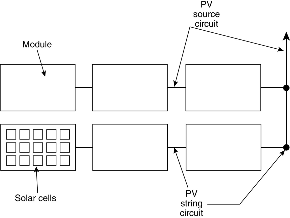
Figure Informational Note Figure 690.1(b) Identification of PV System Components in Common Configurations. Illustration of PV System Components, PV Source Circuit, and dc-to-dc Converter Circuit in a Typical PV Installation.
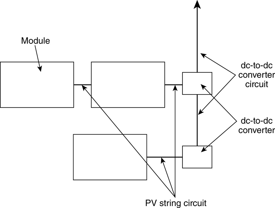
Figure Informational Note Figure 690.1(c) Illustration of PV Source Circuit and dc Combiner in a Typical PV Installation.
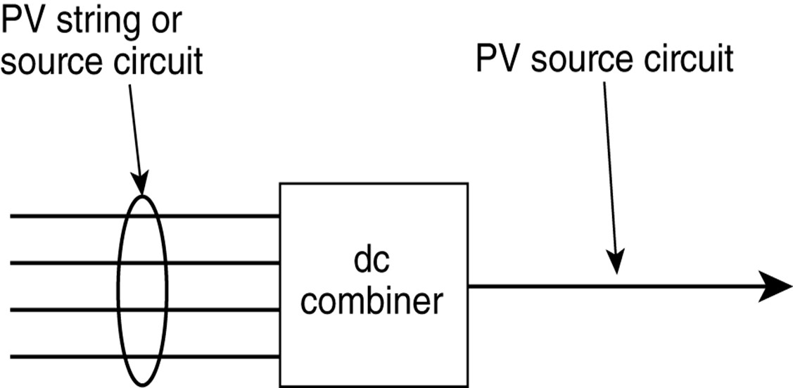
New – 690.4(G)
PV Equipment Floating on Bodies of Water
■ What Changed: A new subdivision (G) was added to 690.4. This change recognizes the installation of floating PV arrays over a body of water and the additional product identification requirements. PV system arrays of modules that float on water are becoming more common, and the requirements for the equipment must be identified. The unique location requires the use of electrical devices and equipment that are suited for the environment. The new text will provide minimum requirements applicable to these types of projects. The new informational note provides additional clarity regarding the unusual conditions that exist for PV arrays located on water.
■ Its Effect: Without the benefit of a specific product safety standard for floating arrays, the CMP needed to address requirements through NEC language. Equipment must be identified for the purpose, and wiring methods must allow for movement.
(G) PV Equipment Floating on Bodies of Water.
PV equipment floating on or attached to structures floating on bodies of water shall be identified as being suitable for the purpose and shall utilize wiring methods that allow for any expected movement of the equipment.
Informational Note: PV equipment in these installations are often subject to increased levels of humidity, corrosion, and mechanical and structural stresses. Expected movement of floating PV arrays is often included in the structural design.
Revision – 690.9(D)
Transformers
■ What Changed: Language was revised in Section 690.9(D), providing a pointer to 705.30(F), where specific requirements applicable to interconnected systems are addressed. Since Article 690 does not provide the requirements for interconnected systems, the language addressing sources on both sides was deleted, and a pointer to 705.30(F) was provided. The language of 705.30(F) addresses the requirements for transformers used with interconnected electric power production sources, where there may be sources of supply connected to both the primary and secondary windings of the transformer. The word “Power” was removed from the title to correlate with Article 450.
■ Its Effect: Clarity and consistency for identification of transformer primary and secondary circuits and resulting overcurrent protection rules are simplified for designers, installers, and inspectors.
(D) Power Transformers.
Overcurrent protection for a transformer with a source(s) on each side shall be provided in accordance with 450.3 by considering first one side of the transformer, then the other side of the transformer, as the primarypower transformers shall be installed in accordance with 705.30(C) 705.30(F).
Exception: A power transformer with a current rating on the side connected toward the interactive inverter output, not less than the rated continuous output current of the inverter, shall be permitted without overcurrent protection from the inverter.
Revision – 690.12
Exception No. 2 & Informational Note
■ What Changed: Rapid shutdown requirements for structures where firefighters will not need to access the roof was removed. The rapid shutdown requirements were created to provide a greater degree of safety for rooftop firefighting operations. The previous language included a limited exception for buildings associated with ground-mounted arrays but did not address other types of structures. The new Exception 2 extends the exception to include carports and other non-enclosed detached structures where firefighting operations do not require roof access.
■ Its Effect: The specific identification of structures exempt from rapid shutdown requirements will provide much-needed clarity for designers, installers, and inspectors.
PV system circuits installed on or in buildings shall include a rapid shutdown function to reduce shock hazard for firefighters in accordance with 690.12(A) through (D).
Exception No. 1: Ground-mounted PV system circuits that enter buildings, of which the sole purpose is to house PV system equipment, shall not be required to comply with 690.12.
Exception No. 2: PV equipment and circuits installed on non-enclosed detached structures including but not limited to parking shade structures, carports, solar trellises, and similar structures shall not be required to comply with 690.12.
Informational Note: Exceptions for rapid shutdown are intended to be consistent with building and fire codes that have limitations as to the types of buildings on which firefighters typically perform rooftop operations.
Revision – 690.12(B)(2)
Inside the Array Boundary
■ What Changed: Two options were revised in Section 690.12(B)(2) for rapid shutdown compliance within the array boundary. The previous option (3) was eliminated. The new UL 3741, PV Hazard Control, standard was created to better address the specific electrical hazards for firefighters when responding to a rooftop incident that includes a PV system. The first option for compliance within the array boundary is through the use of a listed PV shock hazard control system installed in accordance with the manufacturer’s installation instructions. The second option requires the reduction of the voltage within the array to a maximum of 80 volts dc or less within 30 seconds.
■ Its Effect: Designers, installers, and inspectors will have two options for compliance within the array. This will help clarify understanding and compliance for this important safety requirement.
(2) Inside the Array Boundary.
The PV system shall comply with one of the following:
A The PV system shall provide shock hazard control system listed for the purpose shall be firefighters through the use of a PVHCS installed in accordance with the instructions included with the listing or field labeling. Where a hazard control system PVHCS requires initiation to transition to a controlled state, the rapid shutdown initiation device required in 690.12(C) shall perform this initiation.
Informational Note: A listed or hazard PV hazard control system PVHCS is comprised of either an individual piece of equipment that fulfills the necessary functions or multiple pieces of equipment coordinated to perform the functions as described in the installation instructions to reduce the risk of electric shock hazard within a damaged PV array for firefighters. See UL 3741, Photovoltaic Hazard Control.
Controlled conductors located inside the boundary shall be limited The PV system shall provide shock hazard control for firefighters by limiting the highest voltage inside equipment or between any two conductors of a circuit or any conductor and ground inside array boundary to not more than 80 volts within 30 seconds of rapid shutdown initiation. Voltage shall be measured between any two conductors and between any conductor and ground.
PV arrays shall have no exposed wiring methods or conductive parts and be installed more than 2.5 m (8 ft) from exposed grounded conductive parts or ground.
Informational Note: Common methods include the use of PV equipment with a limited maximum voltage of 80 volts as determined by 690.7, PVRSE, PVHCE, or any combination of these.
Revision – 690.15
Disconnecting Means for Isolating Photovoltaic Equipment
■ What Changed: Section 690.15 was rearranged with some grammatical changes. A requirement for an equipment disconnecting means to be within 10 feet of the equipment to now be within sight was also modified. The change goes toward the reorganization of 690.15(C) and (D) in the 2020 NEC. Section 690.15(A) now refers to 690.15(C) for an equipment disconnect and requires the disconnecting means to be within sight and within 10 feet of the equipment or be capable of being lockable in accordance with 110.25 for the 2023 code cycle. Changes in the reorganizing of 690.15(C) do not mandate the 10-foot requirements provided the disconnect complies with 110.25. Also, it only applies to disconnecting means and not isolating devices.
■ Its Effect: Instead of having a prescriptive distance of 10 feet, there will be a more liberal requirement of “in sight of ” which may lead to some enforcement discrepancies. See 110.29 for requirements for “In Sight From (Within Sight From, Within Sight).”
(A) Type of Disconnecting Means.
Where a disconnects are is required to isolate equipment, the disconnecting means shall be one of the following applicable types:
- An equipment disconnecting means in accordance with 690.15(C)shall be required to isolate dc circuits with a maximum circuit current over 30 amperes.
- An isolating device in accordance with 690.15(B) shall be permitted for circuits other than those covered by 690.15(D)(1).as part of listed equipment where an interlock or similar means
- For circuits with a maximum circuit current of 30 amperes or less, an isolating device in accordance with 690.15(B)
Revision – 690.31(B)
Identification and Grouping. (1) Conductors of Different Systems. Exception List Item (2)
■ What Changed: Section 690.31(B) was revised and a new list item (1), Conductors of Different Systems, was added while the previous text in that location was moved to list item (2), Identification. The text revisions provide conditions where PV dc circuits and inverter output circuits can now be installed in the same junction box, pull box or wireway provided they are identified, grouped, and separated in accordance with 690.31 (B)(2) and (B)(3). This change was made to provide relief where inverters are installed in conjunction with a wireway or box.
■ Its Effect: The updated language will grant relief to the electrical professional on installation practices while maintaining separation between dc circuits and ac circuits in the enclosures referenced. Conductors of different systems are still not permitted to share a common raceway.
(B) Identification and Grouping.
PV system dc circuits and Class 1 remote control, signaling, and power-limited circuits of a PV system shall be permitted to occupy the same equipment wiring enclosure, cable, or raceway. PV system dc circuits shall not occupy the same equipment wiring enclosure, cable, or raceway. as other non-PV systems, or inverter output circuits, unless the PV system dc circuits are separated from other circuits by a barrier or partition. PV system circuit conductors shall be identified and grouped as required by 690.31(B)(1) and (B)(2).
Exception: PV system dc circuits utilizing multiconductor jacketed cable or metal-clad cable assemblies or listed wiring harnesses identified for the application shall be permitted to occupy the same wiring method as inverter output circuits and other non-PV systems. All conductors, harnesses, or assemblies shall have an insulation rating equal to at least the maximum circuit voltage applied to any conductor within the enclosure, cable, or raceway.
(1) Conductors of Different Systems.
Where not otherwise allowed in an equipment’s listing, PV system dc circuits shall not occupy the same equipment wiring enclosure, cable, or raceway. as other non-PV systems, or inverter output circuits, unless the PV system dc circuits are separated from other circuits by a barrier or partition.
Exception: Where all conductors or cables have an insulation rating equal to at least the maximum circuit voltage applied to any conductor within the same wiring method, the following shall be permitted:
- Multiconductor jacketed cables for remote control, signaling, or power-limited circuits shall be permitted within the same wiring enclosure, cable, or raceway as PV system dc circuits where all circuits serve the PV system.
- Inverter output circuits shall be permitted to occupy the same junction box, pull box, or wireway with PV system dc circuits that are identified and grouped as required by 690.31(B)(2) and (B)(3).
- PV system dc circuits utilizing multiconductor jacketed cable or metal-clad cable assemblies or listed wiring harnesses identified for the application shall be permitted to occupy the same wiring method as inverter output circuits and other non-PV systems.
(2) Identification.
PV system dc circuit conductors shall be identified at all termination, connection, and splice points by color coding, marking tape, tagging, or other approved means in accordance with 690.31(B)(2)(a) and (B)(2)(b). Conductors relying on other than color coding for polarity identification shall be identified by an approved permanent marking means such as labeling, sleeving, or shrink-tubing that is suitable for the conductor size. The permanent marking means for nonsolidly grounded positive conductors shall include imprinted plus signs (+) or the word POSITIVE or POS durably marked on insulation of a color other than green, white, or gray. The permanent marking means for nonsolidly grounded negative conductors shall include imprinted negative signs (−) or the word NEGATIVE or NEG durably marked on insulation of a color other than green, white, gray, or red. Only solidly grounded PV system dc circuit conductors shall be marked in accordance with 200.6.
Exception: Where the identification of the conductors is evident by spacing or arrangement, further identification shall not be required.
- Conductors relying that rely on other than color coding for polarity identification shall be identified by an approved permanent marking means such as labeling, sleeving, or shrink-tubing that is suitable for the conductor size.
- The permanent marking means for non-solidly grounded positive conductors shall include imprinted plus signs (+) or the word POSITIVE or POS durably marked on insulation of a color other than green, white, or gray. The permanent marking means for nonsolidly grounded negative conductors shall include imprinted negative signs (−) or the word NEGATIVE or NEG durably marked on insulation of a color other than green, white, gray, or red. Only solidly grounded PV system dc circuit conductors shall be marked in accordance with 200.6.
(3) Grouping.
Where the ac and dc conductors of more than one PV systems occupy the same junction box, pull box, or raceway with a removable cover(s)wireway, the PV system ac and dc circuit conductors of each system shall be grouped separately by cable ties or similar means at least once and shall then be grouped at intervals not to exceed 1.8 m (6 ft).
Exception: The requirement for grouping shall not apply if the circuit enters from a cable or raceway unique to the circuit that makes the grouping obvious.
Revision – 690.31(B)(1)
Conductors of Different Systems. – Exception
■ What Changed: Exception revised to permit the dc and ac conductors of a PV system to be located within the same enclosure where all the conductors are insulated for the highest voltage present and grouped appropriately. The previous language prohibited an inverter’s dc and ac conductors from being located within the same field-installed enclosure without a divider. Because the dc and ac conductors will all terminate within the inverter, there is a benefit from a workmanship perspective to permit these conductors within the associated wireway enclosure.
■ Its Effect: This change will simplify the routing of dc and ac PV system conductors to inverters for the installer. The revised format and new exception #2 will permit the common field installation of a wireway beneath an inverter that contains dc and ac conductors insulated for the highest voltage present. The previous rule required a divider to be installed.
(1) Conductors of Different Systems.
Where not otherwise allowed in an equipment’s listing, PV system dc circuits shall not occupy the same equipment wiring enclosure, cable, or raceway. as other non-PV systems, or inverter output circuits, unless the PV system dc circuits are separated from other circuits by a barrier or partition.
Exception: Where all conductors or cables have an insulation rating equal to at least the maximum circuit voltage applied to any conductor within the same wiring method, the following shall be permitted:
- Multiconductor jacketed cables for remote control, signaling, or power-limited circuits shall be permitted within the same wiring enclosure, cable, or raceway as PV system dc circuits where all circuits serve the PV system.
- Inverter output circuits shall be permitted to occupy the same junction box, pull box, or wireway with PV system dc circuits that are identified and grouped as required by 690.31(B)(2) and (B)(3).
- PV system dc circuits utilizing multiconductor jacketed cable or metal-clad cable assemblies or listed wiring harnesses identified for the application shall be permitted to occupy the same wiring method as inverter output circuits and other non-PV systems.
Relocation – 700.2, 701.2, 702.2, and 708.2
Reconditioned Equipment
■ What Changed: Clarification that the reconditioning of transfer switches is not permitted for emergency systems, legally required standby systems, optional standby systems, and critical operations power systems (COPS).
■ Its Effect: This change helps electrical professionals with what equipment can and cannot be reconditioned. Stating this in these articles enhances the usability of the Code and provides definite direction concerning these items.
700.2 Reconditioned Equipment.
Reconditioned transfer switches shall not be permitted.
701.2 Reconditioned Equipment.
Reconditioned transfer switches shall not be permitted.
702.2 Reconditioned Equipment.
Reconditioned transfer switches shall not be permitted.
708.2 Reconditioned Equipment.
Reconditioned transfer switches shall not be permitted.
New / Revision – 700.3(F)
List items (4), (6), and (7).
■ What Changed: Revised subdivision (F) to include revised list item (4) requiring listing, added a new (6) for the permanent connection point and routing requirements for cables, and a new (7) requiring a label to be field applied at the permanent connection point. There have been life safety concerns experienced or expressed when alternate power sources are being maintained or repaired.
■ Its Effect: This change will give clarification and guidance to the electrical professional, helping to reduce inaccurate labeling at the connection point and reduce cable damage and building egress concerns. The installer and inspector must work together to ensure a safe system is in place during the repair or maintenance of alternate power sources.
(F) Temporary Source of Power for Maintenance or Repair of the Alternate Source of Power.
If the emergency system relies on a single alternate source of power, which will be disabled for maintenance or repair, the emergency system shall include permanent switching means to connect a portable or temporary alternate source of power, which that shall be available for the duration of the maintenance or repair. The permanent switching means to connect a portable or temporary alternate source of power shall comply with the following:
- Connection to the portable or temporary alternate source of power shall not require modification of the permanent system wiring.
- Transfer of power between the normal power source and the emergency power source shall be in accordance with 700.12.
- The connection point for the portable or temporary alternate source shall be marked with the phase rotation and system bonding requirements.
- Mechanical or electrical interlocking shall The switching means, including the interlocks, shall be listed and provided with mechanical or mechanical and electrical interlocking to prevent inadvertent interconnection of power sources.
- The switching means shall include a contact point that shall annunciate at a location remote from the generator or at another facility monitoring system to indicate that the permanent emergency source is disconnected from the emergency system.
- The permanent connection point for the temporary generator shall be located outdoors and shall not have cables from the connection point to the temporary generator routed through exterior windows, doors, or similar openings.
- A permanent label shall be field applied at the permanent connection point to identify the system voltage, maximum amperage, short-circuit current rating of the load side of equipment supplied, and ungrounded conductor identification in accordance with 210.5.
Revision – 700.5(D)
Redundant Transfer Equipment
■ What Changed: The structure of 700.5 concerning transfer equipment now mirrors the subdivisions for transfer equipment found in Article 708.24. New subdivision (D) describes the functionality needed when a single feeder supplies emergency loads. Previously the language described how to do this based on a single product available on the market. There are multiple ways to meet the requirements safely and reliably and ensure continuity of power when a single feeder supplies an emergency load.
■ Its Effect: This change will improve consistency between code articles and enhance useability for the electrical professional. It also allows the NEC not to be seen as specifying a specific brand of electrical equipment. The previous text could prove problematic and burdensome for the AHJ and installers.
(D) Redundant Transfer Equipment.
If emergency loads are supplied by a single feeder, the emergency power system shall include redundant transfer equipment or a bypass isolation transfer switch to facilitate maintenance as required in 700.3(C) without jeopardizing continuity of power. If the redundant transfer equipment or bypass isolation transfer switch is manual (or nonautomatic), then it shall be actively supervised by a qualified person when the primary (automatic) transfer equipment is disabled for maintenance or repair.
Exception: The requirement for a bypass isolation redundancy with the transfer switch equipment shall not apply where any of the following conditions exists:
- All processes that rely on the emergency system source are capable of being disabled during maintenance or repair activities without jeopardizing the safety to human life.
- The building or structure is unoccupied and fire protection systems are fully functional and do not require an alternate power source.
- Other temporary means shall be permitted to be substituted for the emergency system.
- A written emergency plan that includes mitigation actions and responsibilities for qualified persons to address the recognized site hazards for the duration of the maintenance or repair activities shall be developed and implemented. The emergency plan shall be made available to the authority having jurisdiction.
New – 700.11(C)
Wiring, Class 2 Powered Emergency Lighting Systems
■ What Changed: New requirements added for the separation of Class 2 circuits designated as emergency or nonemergency circuits in Section 700.11(C). The separation of Class 2 circuits used for different purposes was not defined in the previous edition, so 700.11(C) was created to define acceptable methods clearly.
■ Its Effect: Separation of circuits allows the installer and inspector to readily identify by bundled Class 2 circuits from emergency and nonemergency circuits or by bundling or barrier separation. This change provides additional integrity to the emergency lighting system in so far as it prevents collateral damage during maintenance activities.
(C) Separation of Circuits.
Class 2 emergency circuits shall be wired in a listed, jacketed cable or with one of the wiring methods of Chapter 3. If installed alongside nonemergency Class 2 circuits that are bundled, Class 2 emergency circuits shall be bundled separately. If installed alongside nonemergency Class 2 circuits that are not bundled, Class 2 emergency circuits shall be separated by a nonconductive sleeve or nonconductive barrier from all other Class 2 circuits. Class 2 emergency circuits shall be separated from nonemergency Class 2 circuits. Separation from other circuits shall comply with 725.136.
New – 700.12(C)
Supply Duration
■ What Changed: An informational note was added to reference classification information for emergency power supply systems (EPSS) used with emergency systems. It will clarify that all Emergency and Standby Power Systems (EPSS) now require a minimum of not less than two hours of fuel for operation from the previous 1 ½ hours. This change will ensure all EPSS have the same required rating and capacity to supply and maintain the total load for a minimum period of 2 hours without being refueled or recharged.
■ Its Effect: This change should bring clarity to the electrical professionals for the requirements for EPSS installations used with emergency systems. The change in the Standard for Emergency and Standby Power Systems (EPSS) require consistent hours of operation regardless of the type of system installed. Testing these different EPSS installations will also become consistent as required in NFPA 110.
(C) Storage Battery Supply Duration.
Storage batteries shall be of suitable rating and capacity to supply and maintain the total load for a minimum period of 11⁄2 hours, without the voltage applied to the load falling below 871⁄2 percent of normal. Automotive-type batteries shall not be used The emergency power source shall be of suitable rating and capacity to supply and maintain the total load for the duration determined by the system design. In no case shall the duration be less than 2 hours of system operation unless used for emergency illumination in 700.12(C)(4) or unit equipment in 700.12(I). Additionally, the power source shall comply with 700.12(C)(1) through (C)(5) as applicable.
An automatic battery charging means shall be provided.
Informational Note: See NFPA 110-2022, Standard for Emergency and Standby Power Systems, for information on classification of emergency power supply systems (EPSS).
(1) On-Site Fuel Supply.
Where internal combustion engines are used as the prime mover, an An on-site fuel supply shall be provided, with an on-premises fuel supply sufficient for not less than 2 hours’ operation of the system.
(2) Fuel Transfer Pumps.
Where power is needed for the operation of the fuel transfer pumps to deliver fuel to a generator set day tank, this pump the source, these pumps shall be connected to the emergency power system.
(3) Public Gas System, Municipal Water Supply.
Prime movers Sources shall not be solely dependent on a public utility gas system for their fuel supply or municipal water supply for their cooling systems.
Exception: Where approved by the authority having jurisdiction, the use of other than on-site fuels shall be permitted where there is a low probability of a simultaneous failure of both the off-site fuel delivery system and power from the outside electrical utility company. Where the public gas system is approved, the requirements of 700.12(C)(1) shall not apply.
(4) Storage Batteries and UPS.
Storage batteries and uninterruptable power supply systems used to supply emergency illumination shall be of suitable rating and capacity to supply and maintain the total load for a minimum period of 11⁄2 hours, without the voltage applied to the load falling below 871⁄2 percent of normal nominal voltage. Automotive-type batteries shall not be used. An automatic battery charging means shall be provided.
(5) Automatic Fuel Transfer
Where dual fuel supplies sources are used, means shall be provided for automatically transferring from one fuel supply source to another.
Revision – 700.12(E) & 701.12(E)
Stored-Energy Power Supply Systems (SEPSS)
■ What Changed: The title of Sections 700.12(E) and 701.12(E) have been changed from “Uninterruptible Power Supplies” to “Stored-Energy Power Supply Systems (SEPSS).” These revisions expand what will be encountered for the newly defined stored-energy power supply systems (SEPSS). This includes items such as an uninterruptible power supply (UPS), fuel cell systems, energy storage systems (ESS), storage batteries for DC loads, and any “other” option complying with 700.12 since these technologies may not represent an all-inclusive list.
■ Its Effect: This change recognizes more options that are now available to the electrical professional for stored-energy power supply system (SEPSS) installations. The professionals will need to be aware that new options exist and understand the guidelines associated with their installation.
(E) Uninterruptible Power Supplies Stored-Energy Power Supply Systems (SEPSS).
Uninterruptible power supplies used to provide power for emergency systems shall comply with the applicable provisions of 700.12(B) and (C)Stored energy power supply systems shall comply with 700.12(E)(1) and (E)(2).
(1) Types.
Systems shall consist of one or more of the following system types:
- Uninterruptible power supply (UPS)
- Informational Note: See UL 1778, Uninterruptible Power Systems, for further information.
- Fuel cell system
- Energy storage system (ESS)
- Storage battery
- Other approved equivalent stored energy sources that comply with 700.12
(2) Fire Protection, Suppression, Ventilation, and Separation.
The systems in 700.12(E)(1) shall be installed with the fire protection, suppression, ventilation, and separation requirements specified in the manufacturer’s instructions or equipment listing.
Informational Note: See NFPA 853-2020, Standard for the Installation of Stationary Fuel Cell Power Systems, and NFPA 855-2020, Standard for the Installation of Stationary Energy Storage Systems, for additional information on fire protection installation
Revision – 700.12(G)
Microgrid Systems
■ What Changed: The existing 700.12(G) was moved into 700.12(E) and replaced with a new 700.12(G) titled Microgrid Systems. Existing Section 700.12(G) was replaced, recognizing there are different types of microgrids, in addition to any that might be categorized as dc only.
■ Its Effect: This change provides additional guidance to electrical professionals when designing, installing, or inspecting on-site sources that have been designated as emergency sources connected to microgrid systems.
(G) DC Microgrid Systems.
Sources connected to a dc microgrid system shall be permitted where the system is capable of being isolated from all non-emergency sources On-site sources, designated as emergency sources, shall be permitted to be connected to a microgrid system.
DC microgrid systems used as a source of power for emergency systems shall be of suitable rating and capacity to supply and maintain the total emergency load for not less than 2 hours of full-demand operation The system shall isolate the emergency system from all nonemergency loads when the normal electric supply is interrupted or shall meet the requirements of 700.4(C). Interruption or partial or complete failure of the normal or nonemergency source(s) shall not impact the availability, capacity, and duration provided by the designated emergency sources.
Where a dc microgrid system source serves as the normal supply for the building or group of buildings concerned, it shall not serve as the sole source of power for the emergency standby system The designated stored-energy electrical emergency power source(s) of a microgrid system shall be permitted to remain interconnected to any available power production source during operation of the emergency source(s) where the lack of, or failure of, the interconnected power production source(s), or related controls, does not impact system operation. Interconnected power production sources, other than the designated stored emergency power source(s), shall not be required to meet the requirements of Article 700.
Revision – 701.4(C)
Load Management
■ What Changed: Modifications made to the title of Section 701.4(C), which now simply addresses load management requirements. “Peak load shaving” has been removed from the title. Parallel source requirements are addressed in 701.4(D), titled Parallel Operation.
■ Its Effect: This new section is being added to aid electrical professionals in more easily identifying the requirements unique to power sources used in legally required systems that can operate in parallel with a normal source.
(C) Load Pickup and Load Shedding Management.
The alternate power source shall be permitted to supply legally required standby and optional standby system loads where the alternate source has adequate capacity or where load management (that includes automatic selective load pickup and load shedding are provided )is provided that will ensure adequate power to the legally required standby circuits.
New – 701.4(D)
Parallel Operation
■ What Changed: Language added that now identifies the two different types of parallel operation, normal and alternate sources, of legally required systems in new Section 701.4(D). Normal Source was added at 701.4(D)(1) to provide the requirements of interconnected electric power production sources found in Article 705. These are to be maintained at all times and also comply with Part I and II of Article 705. Additionally, the signaling of system malfunction per 701.6(A) regardless of any failure within the operation of legally required standby system(s) that would compromise the capacity requirements now notifies the user of the operating system(s) distress.
■ Its Effect: The electrical installer and the inspector are provided a clear direction of which system(s) is effectively operational and any reduction of load capacity causing system(s) malfunction. The added changes ensure the required standby load is maintained at all times as well as while keeping the economy in mind, using the alternate source(s) during their most efficient or peak production times could be considered.
(D) Parallel Operation.
Parallel operation shall comply with Part I or Part II of Article 705 where the legally required source capacity required to supply the legally required load is maintained at all times. Parallel operation of the legally required source(s) shall consist of the sources specified in 701.4(D)(1) and (D)(2).
(1) Normal Source.
The alternate power source shall be permitted to operate in parallel with the normal source in compliance with Part I or Part II of Article 705 where the capacity required to supply the legally required standby load is maintained at all times. Any operating condition that results in less than the required source capacity shall initiate a legally required standby source malfunction signal in 701.6(A).
Parallel operation shall be permitted for satisfying the test requirements of 701.3(B), provided all other conditions of 701.3 are met.
Informational Note: Peak load shaving is one application for parallel source operation.
(2) Alternate Source.
Legally required standby sources shall be permitted to operate in parallel where the necessary equipment to establish and maintain a synchronous condition is provided.
New – 701.10
Wiring Legally Required Standby Systems
■ What Changed: A new first-level subdivision (B) was added and new figure informational notes concerning wiring requirements for legally required standby systems to Section 701.10. This addition provides a correlation with 700.10(B)(5)(b). These systems are installed to supply legally required loads, such as heating and refrigeration systems, communications systems, ventilation, and smoke removal systems, sewage disposal, lighting systems, and industrial processes. If these loads are interrupted due to a failure of the normal
building service, it could create hazards or hamper first responder operations.
■ Its Effect: The electrical professional now has additional guidance and clarification for wiring and overcurrent protection options associated with a feeder(s) for legally required systems. Understanding these requirements is critical to the safety of these very important systems.
701.10 Wiring Legally Required Standby Systems.
The legally required standby system wiring shall be permitted to occupy the same raceways, cables, boxes, and cabinets with other general wiring.
(A) General.
The legally required standby system wiring shall be permitted to occupy the same raceways, cables, boxes, and cabinets with other general wiring.
(B) Wiring.
Wiring from a legally required source to supply legally required and other (non-legally required) loads shall be in accordance with the following:
- The common bus of switchgear, sections of a switchboard, or individual enclosures shall be either of the following:
- Supplied by single or multiple feeders without overcurrent protection at the source
- Supplied by single or multiple feeders with overcurrent protection, provided that the overcurrent protection that is common to a legally required system and any non-legally required system(s) is selectively coordinated with the next downstream overcurrent protective device in the non-legally required system(s)
Informational Note: See Informational Note Figure 701.10(B)(a) and Informational Note Figure 701.10(B)(b) for further information.
New – 701.12(C)
Supply Duration
■ What Changed: An informational note added at Section 701.12(C) to reference classification information for emergency power supply systems (EPSS) used with legally required standby systems. This will clarify that all Emergency and Standby Power Systems (EPSS) now require a minimum of not less than 2 hours of fuel for operation from the previous 1 ½ hours. This update will ensure all EPSS have the same required rating and capacity to supply and maintain the total load for a minimum period of 2 hours without being refueled or recharged.
■ Its Effect: This change should bring clarity to the electrical professionals for the requirements for EPSS installations with legally required standby systems. The change in the Standard for Emergency and Standby Power Systems (EPSS) require consistent hours of operation regardless of the type of system installed. Testing these different EPSS installations will also become consistent as required in NFPA 110.
(C) Storage Battery Supply Duration.
The alternate power source shall be of suitable rating and capacity to supply and maintain the total load for the duration determined by the system design. In no case shall the duration be less than 2 hours of system operation. Additionally, the power source shall comply with 701.12(C)(1) through (C)(5) as applicable.
Informational Note: See NFPA 110-2022, Standard for Emergency and Standby Power Systems, for information on classification of emergency power supply systems (EPSS).
Revision – 705.11
Source Connections to a Service
■ What Changed: Section 705.11 has been completely revised and applies to systems interconnected with a new or existing utility service. None of the revised 705.11 language provides any new requirements. The entire section is now a restatement of existing Article 230 and Article 250 rules.
■ Its Effect: This change is intended to provide the electrical professional with enhanced usability and clarity regarding the basic applicable requirements of NEC Chapters 1–4.
705.11 Source Connections to a Service.
Note: See NEC for Complete Text
Relocation – 705.13
Energy Management Systems (EMS)
■ What Changed: Most of the requirements that were located in Section 705.13 have been deleted. The requirements previously located in 705.13 were relocated to Article 750 entitled Energy Management Systems.
■ Its Effect: This should have a positive impact on the electrical industry as the requirements are all now in one location. It should also aid in usability and greater understanding by the electrical professional concerning these requirements.
705.13 Power Control Energy Management Systems (EMS).
A power control system (PCS) shall be listed and evaluated to control the output of one or more power production sources, energy storage systems (ESS), energy management systems, and other equipment. The PCS shall limit current and loading on the busbars and conductors supplied by the PCS An EMS in accordance with 750.30 shall be permitted to limit current and loading on the busbars and conductors supplied by the output of one or more interconnected electric power production or energy storage sources.
Informational Note: A listed power control system (PCS) is a type of EMS that is capable of monitoring multiple power sources and controlling the current on busbars and conductors to prevent overloading. See UL 1741, Inverters, Converters, Controllers and Interconnection System Equipment for Use with Distributed Energy Resources, and UL 916, Energy Management Equipment, for information on PCS and EMS.
For the circuits connected to a PCS, the PCS shall limit the current to the ampacity of the conductors or the ampere ratings of the busbars to which it is connected in accordance with 705.13(A) through (E).
Deletion – 705.20
Source Disconnecting Means
■ What Changed: The requirement for enclosure covers in Section 705.20 requiring a tool to open or be locked has been deleted. This action was taken due to the language that exists at 404.30. This information is applicable throughout the NEC and will continue to protect unqualified people from accessing the equipment and becoming injured.
■ Its Effect: This change will add clarity for the electrical professional as it will remove a redundant requirement. The information located at Section 404.30, Switch Enclosures with Doors, will provide the necessary information for these installations.
705.20 Source Disconnecting Means.
Means shall be provided to disconnect power source output circuit conductors of electric power production equipment from conductors of other systems. Specific source disconnecting means required elsewhere in this Code that comply with 705.20 shall be permitted to meet this requirement. A single disconnecting means in accordance with 705.20 shall be permitted to disconnect multiple power sources from conductors of other systems.
Informational Note: See 480.7, Part II of Article 445, Part II,III of Article 690, Part III,of Article 692, Part III,of Article 694, and Part IIIII of and Article 706Part II for specific source disconnecting means requirements.
The disconnecting means shall comply with the following:
- Be one of the following types:
- A manually operable switch or circuit breaker
- A load-break-rated pull-out switch
- A power-operated or remote-controlled switch or circuit breaker that is manually operable locally and opens automatically when control power is interrupted
- A device listed or approved for the intended application
- Simultaneously disconnect all ungrounded conductors of the circuit
- Located where readily accessible
- Externally operable without exposed live parts
- Enclosures with doors or hinged covers containing exposed energized parts when the door or cover is open that require a tool to open or are locked where readily accessible to unqualified persons
- Plainly indicate whether in the open (off) or closed (on) position
- Have ratings sufficient for the maximum circuit current, available fault current, and voltage that is available at the terminals
- Where the line and load terminals are capable of being energized in the open position, be marked with the following words or equivalent:
New – 705.30(F)
Transformers
■ What Changed: New language has been added at Section 705.30(F) to address transformer requirements for interconnected systems. The revised language now correlates with the transformer installation rules of Articles 240, 450, and the transformer product safety standard. This change was necessary to ensure that proper overcurrent protection is provided for transformer secondary conductors where sources of supply are connected to both sides.
■ Its Effect: Clarity and consistency for identifying transformer primary and secondary circuits and resulting overcurrent protection rules in interconnected systems are simplified for designers, installers, and inspectors.
(F) Power Transformers.
Transformers with sources on each side shall be provided with overcurrent protection in accordance with 450.3. The primary shall be the side connected to the largest source of available fault current. Secondary protection shall not be required for a transformer secondary that has a current rating not less than the sum of the rated continuous output currents of the power sources connected to that secondary.
The following apply to the installation of transformers:
- For the purpose of overcurrent protection, the primary side of transformers with sources on each side shall be provided with overcurrent protection in accordance with 450.3. The primary shall be the side connected to the largest source of available fault current.
- Transformer secondary conductors shall be protected in accordance with 240.21(C).
Revision – 705.50
System Operation
■ What Changed: The language describing the operational modes of a Microgrid in Section 705.50 was rewritten to clearly state that a microgrid can operate in parallel with other systems or in island mode. This will help with clarification and to make sure the language is consistent with other NEC sections. A new Informational Note has been added to address health care facilities that have plans for microgrid installations.
■ Its Effect: It will add clarity for the electrical professional to the operational functionality of a microgrid.
705.50 System Operation.
Microgrid Interconnected microgrid systems shall be permitted to disconnect from capable of operating in interactive mode with a primary source of power or electric utility or other interconnected electric power production and distribution network. Microgrid systems shall be permitted to disconnect from other sources and operate as an isolated microgrid system operating in island mode.
Informational Note: Microgrid systems often include a single source or a compatible interconnection of multiple sources such as engine generators, solar PV, wind, or ESS.
Informational Note No. 2: See Article 517 for health care facilities incorporating microgrids.
New – 706.7
Commissioning and Maintenance (Energy Storage Systems)
■ What Changed: Commissioning requirements have been added, which will now align with requirements found in Chapter 6 of NFPA 855-2020, Standard for the Installation of Stationary Energy Storage Systems. The existing text has been revised, adding commissioning requirements for energy storage systems in a new subdivision (A). The existing requirements for maintenance of these systems were moved into the new (B).
■ Its Effect: These additions will require commissioning of the energy storage systems upon installation for other than one- and two-family dwellings installations. The electrical professional will need to provide necessary maintenance in accordance with manufacturer requirements or other industry standards. It assures the energy storage system will operate properly and in a safe condition.
706.7 Commissioning and Maintenance.
Energy storage systems shall be maintained in proper and safe operating condition. The required maintenance shall be in accordance with the manufacturer’s requirements and industry standards. A written record of the system maintenance shall be kept and shall include records of repairs and replacements necessary to maintain the system in proper and safe operating condition.
Informational Note: For information related to general electrical equipment maintenance and developing an effective electrical preventive maintenance (EPM) program, see NFPA 70B-2019, Recommended Practice for Electrical Equipment Maintenance, or ANSI/NETA ATS-2017, Standard for Acceptance Testing Specifications for Electrical Power Equipment and Systems.
(A) Commissioning.
ESSs shall be commissioned upon installation. This shall not apply in one- and two-family dwellings.
Informational Note: See NFPA 855-2020, Standard for the Installation of Stationary Energy Storage Systems, for information related to the commissioning of ESSs.
(B) Maintenance.
Energy storage systems ESSs shall be maintained in proper and safe operating condition. The required maintenance shall be in accordance with the manufacturer’s requirements and industry standards. A written record of the system maintenance shall be kept and shall include records of repairs and replacements necessary to maintain the system in proper and safe operating condition. This shall not apply in one- and two-family dwellings.
Informational Note: For See NFPA 70B-2019, Recommended Practice for Electrical Equipment Maintenance, or ANSI/NETA ATS-2017, Standard for Acceptance Testing Specifications for Electrical Power Equipment and Systems, for information related to general electrical equipment maintenance and developing an effective electrical preventive maintenance (EPM) program, see NFPA 70B-2019, Recommended Practice for Electrical Equipment Maintenance, or ANSI/NETA ATS-2017, Standard for Acceptance Testing Specifications for Electrical Power Equipment and Systems.
New – Article 722
Cables for Power-Limited Circuits, Fault-Managed Power (Class 4) Circuits
■ What Changed: A new Article 722 was created for the general requirements for cables used with power-limited circuits and fault-managed power (Class 4) circuits installations. Wiring requirements for these cables were located throughout Chapter 7 of the NEC, making it hard to find at times. With these requirements relocated to one location (the new Article 722), it is anticipated the user of the Code will have an easier time finding the requirements.
■ Its Effect: There are concerns that installations and inspections of work covered in Chapter 7 are not done to the level you would find for installations covered by Chapters 1-4. This change is intended to make it easier for the electrical professional to find requirements, aiding in installation and enforcement.
Article 722 Cables for Power-Limited Circuits, Fault-Managed Power (Class 4) Circuits, and Optical Fiber
722.1 Scope.
This article covers the general requirements for the installation of single- and multiple-conductor cables used in Class 2 and Class 3 power-limited circuits, power-limited fire alarm (PLFA) circuits, Class 4 fault-managed power circuits, and optical fiber installations.
Note: See NEC for Complete Text
Revision – 725.144
Bundling of Cables Transmitting Power and Data
■ What Changed: The words “4-Pair” were removed from the title of Section 725.144 and added it to the title subdivision (A), where it was applicable to the types of cables discussed. This change clarifies that 725.144 applies to any pair of cables and that only subdivision (A) and Table 725.144 apply to 4-pair cables. Subdivision (B) covers cables of any pair count and requires an “LP” listing. See UL 13, Standard for Safety Power-Limited Circuit Cables, that does not limit rating to 4-pair cables.
■ Its Effect: This change will help both installers and inspectors by clarifying the requirements for 4-pair cables and other cables. This change also provides a possible placeholder for future requirements concerning single-pair ethernet cables.
725.144 Transmission of Bundling of 4 Cables Transmitting Power and Data.
Sections 725.144(A) and (B) shall apply to Class 2 and Class 3 circuits that transmit power and data to a powered device over listed cabling. Section 300.11 and Parts I and III of Article 725 shall apply to Class 2 and Class 3 circuits that transmit power and data. The conductors that carry power for the data circuits shall be copper. The current in the power circuit shall not exceed the current limitation of the connectors.
(A) Use of 4-Pair Class 2 or Class 3 Cables to Transmit Power and Data.
Where Types Type CL3P, Type CL2P, Type CL3R, Type CL2R, Type CL3, or Type CL2 4-pair cables transmit power and data, the rated current per conductor of the power source shall not exceed the ampacities in Table 725.144 at an ambient temperature of 30°C (86°F). For ambient temperatures above 30°C (86°F), the correction factors in Table 310.15(B)(1)(1) or in Equation 310.15(B) shall apply.
(B) Use of Class 2-LP or Class 3-LP Cables to Transmit Power and Data.
Types Type CL3P-LP, Type CL2P-LP, Type CL3R-LP, Type CL2R-LP, Type CL3-LP, or Type CL2-LP cables shall be permitted to supply power to equipment from a power source with a rated current per conductor up to the marked current limit located immediately following the suffix “-LP” and shall be permitted to transmit data to the equipment. Where the number of bundled LP cables is 192 or less and the selected ampacity of the cables in accordance with Table 725.144 exceeds the marked current limit of the cable, the ampacity determined from the table shall be permitted to be used. For ambient temperatures above 30°C (86°F), the correction factors of Table 310.15(B)(1)(1) or Equation 310.15(B) shall apply. The Class 2-LP and Class 3-LP cables shall comply with the following, as applicable:
New – Article 726
Class 4 (CL4) Power Systems
■ What Changed: A new Article 726 was created for fault-managed power (FMP) systems in occupancies other than dwelling units. There have been over 1,000 installations of “Digital Electricity” in the United States, mostly at stadiums where large numbers of people gather. A failure in this environment could be disastrous, causing needless loss of life.
■ Its Effect: Class 4 systems have ground-fault circuit-interrupter (GFCI) equivalent protection (line to ground) while also introducing similar protection line to line. This allows for installations that do not require raceway systems. The higher voltage associated with this technology leads to lower current. This allow the electrical professional to install smaller conductors when compared to 120-volt AC systems. This reduces the materials required for installs, leading to a ‘greener’ construction project. Class 4 systems allow power in the kW range to be delivered using wiring methods more like Class 2 and Class 3 methods, other than methods found in Chapter 3. Smaller systems allow for greater floor space for the building owners to use for other purposes. A Class 4 system is envisioned to enable smart building expansion while allowing the natural integration of grid power with renewable and battery sources.
Article 726 Class 4 Fault-Managed Power Systems.
726.1 Scope.
This article covers the installation of wiring and equipment of fault-managed power (FMP) systems inoccupancies other than dwelling units, including utilization equipment incorporating parts of these systems.
Note: See NEC for Complete Text
Revision / Relocation – Article 760
Fire Alarm Systems
■ What Changed: Several sections throughout Article 760 were reworded, revised, relocated, or deleted. Hazardous (Classified) Location requirements were reworded and relocated to 760.12 to be consistent with Article 722. Some requirements applying to cables have been relocated to Article 722.
■ Why it happened: These changes were part of the consolidation efforts towards requirements found throughout the NEC and moved into new Article 722. The end goal was greater useability.
■ Its Effect: The new requirements at 760.12 make it clear that these specialty cables are not exempt from requirements for Hazardous (Classified) Locations. The reference to the full articles has changed to specific section references to comply with the NEC Style Manual.
Article 760 Fire Alarm Systems
760.1 Scope.
This article covers the installation of wiring and equipment of fire alarm systems, including all circuits controlled and powered by the fire alarm system.
Note: See NEC for Complete Text
Relocation – 800.179
Wires and Cables
■ What Changed: Hybrid power and communications cable general requirements were moved to Article 800 with the other communication cable types. This revision revises the title from “Communications Wires and Cables” to “Wires and Cables” to avoid confusion and also moves the listing and marking requirements to this article. This section has general listing requirements for all cables in Chapter 8. The revised text clarifies that all wires and cables, except CATV-type cables, are required to have a minimum voltage rating of 300 volts.
■ Its Effect: The changes add usability to the NEC and increase safety for electrical systems. It simplifies the listing and marking requirements for enhanced usability by the electrical professional.
800.179 Plenum, Riser, General-Purpose, and Limited Use Wires and Cables.
Plenum, riser, general-purpose, and limited-use Communications wires and cables, community antenna television cables, and network-powered broadband communications cables shall be listed in accordance with 800.179(A) through (D) (I) and shall have a temperature rating of not less than 60°C (140°F). The temperature rating shall be marked on the jacket of cables that have a temperature rating exceeding 60°C (140°F). The cable voltage rating shall not be marked on the cable. Conductors in communications cables, other than in a coaxial cable, shall be copper. Cables shall be permitted to contain optical fibers. Cables containing optical fibers shall be marked with the suffix “-OF.”
Communications wires and cables and network-powered communications cables shall have a voltage rating of not less than 300 volts. The insulation for the individual conductors, other than the outer conductor of a coaxial cable, shall be rated for 300 volts minimum. The cable voltage rating shall not be marked on the cable or on the under-carpet communications wire.
Note: See NEC for Complete Text
Relocation – 805.170
Protectors
■ What Changed: Communication equipment listing requirements were moved to Article 800 leaving two subdivisions (A) and (B) for primary and secondary protectors.
■ Its Effect: These changes will assist users of the Code by specifying these protective devices to be listed. It will help assure the safety of communication systems.
805.170 Equipment Protectors.
Communications equipment shall be listed as being suitable for electrical connection to a communications network Protectors shall be listed in accordance with 805.170(A) or 805.170(B).
Informational Note No. 1: See ANSI/UL 60950-1-2014, Standard for Safety of Information Technology Equipment, ANSI/UL 1863-2012, Standard for Safety Communications Circuit Accessories, or ANSI/UL 62368-1-2014 or ANSI/UL 62368-1-2018, Audio/Video, Information and Communication Technology Equipment — Part 1: Safety Requirements.
Informational Note No. 2: See ANSI/ATIS 0600337-2016, Requirements for Maximum Voltage, Current, and Power Levels Used in Communications Circuits, for additional information regarding voltages, currents, and power allowed on communications circuits.
(A) Primary Protectors.
The primary protector shall be listed and consist of an arrester connected between each line conductor and ground in an appropriate mounting. Primary protector terminals shall be marked to indicate line and ground as applicable.
Informational Note: See ANSI/UL 497-2017, Standard for Protectors for Paired Conductor Communications Circuits, to determine applicable requirements for a listed primary protector.
(B) Secondary Protectors.
The secondary protector shall be listed as suitable to provide means to safely limit currents to less than the current-carrying capacity of listed indoor communications wire and cable, listed telephone set line cords, and listed communications terminal equipment having ports for external wire line communications circuits. Any overvoltage protection, arresters, or grounding connection shall be connected on the equipment terminals side of the secondary protector current-limiting means.
Informational Note: See ANSI/UL 497A-2019, Standard for Secondary Protectors for Communications Circuits, to determine applicable requirements for a listed secondary protector.
Revision – 840.160
Powering Circuits
■ What Changed: The reference from Section 725.154(A) was changed to Section 722.135(E) as cable substitution, and installation requirements are now in Article 722.
■ Its Effect: This revision makes Chapter 8 more user-friendly and helps avoid confusion while also moving the listing and marking requirements to Article 800. This section has general listing requirements for all cables referenced in Chapter 8.
840.160 Powering Circuits.
Communications cables listed in accordance with 805.179Listed communications cables, in addition to carrying the communications circuit, shall also be permitted to carry circuits for powering listed communications equipment listed in accordance with 805.170. The power source shall be listed in accordance with 840.170(C). Installation of the listed 4-pair communications cables for a communications circuit or installation where 4-pair communications cables are substituted for Class 2 and Class 3 cables in accordance with 725.154(A)722.122(E) shall comply with 725.144.
Exception: Installing communications cables in compliance with 725.144 shall not be required for listed 4-pair communications cables where the rated current of the power source does not exceed 0.3 amperes in any conductor 24 AWG or larger.
Informational Note No. 1: A typical communications cable for this application is a 4-pair cable sometimes referred to as Category 5e (or higher) LAN cable or balanced twisted pair cable. These types of cables are often used to provide Ethernet- and Power over Ethernet (PoE)-type services.
Informational Note No. 2: See 725.144 for requirements to manage the temperature rise of bundles of cables that provide power.
New – Chapter 9 Table 13
Equipment Suitable for Hazardous (Classified) Locations
■ What Changed: New Table 13 created in Chapter 9 entitled Equipment Suitable for Hazardous (Classified) Locations. The text was deleted at 505.9(C)(2)(4) referencing Table 505.9 (C)(2)(4) with new text added to reference Chapter 9 Table 13. The requirements at 505.9(C)(2)(4) discuss zone equipment marking requirements. The new table provides a complete list of the types of protection for hazardous (classified) locations and improves the readability of 505.9(C)(2)(4).
■ Its Effect: This will assist the electrical industry by providing an improved list of equipment suitability for various locations. The new table and revisions will assist the designer, contractors, and the AHJ verify compliance with code and the manufacturer’s listing of the equipment that will be installed in a hazardous (classified) location for both zone and other classified locations.
Table 13 Equipment Suitable for Hazardous (Classified) Locations
Note: See NEC for Complete Text
Revision / New – Informative Annex A
Product Safety Standards
■ What Changed: The existing Informative Annex A was revised in order to reflect the current editions of safety standards and a new Table A.1(B) was added addressing product safety standards for conductors and equipment that do not have associated listing requirements.
■ Its Effect: Finding information quickly is important to the electrical professional as to applying the requirements of the NEC. These revisions and the addition of the new table allow the Code user to utilize Annex A with better clarity. This is an effort to increase access to relevant product and safety standards, thus increasing electrical safety.
Informative Annex A Product Safety Standards
Informative Annex A is not a part of the requirements of this NFPA document but is included for informational purposes only.
This informative annex provides a list of product safety standards used for product listing where that listing is required by this Code. It is recognized that this list is current at the time of publication but that new standards or modifications to existing standards can occur at any time while this edition of the Code is in effect.
This informative annex does not form a mandatory part of the requirements of this Code but is intended to identify for the Code users the standards upon which Code requirements have been based.
Note: See NEC for Complete Text
New – Informative Annex E
Fire Resistance Construction
■ What Changed: E.2.1 for Type IV construction now includes traditional heavy timber construction and mass timber construction. These new changes provide alignment with the Model Building Codes.
■ Its Effect: Changes were required to address the addition of mass timber buildings to Type IV construction in the model building codes.
Informative Annex E Types of Construction
This informative annex is not a part of the requirements of this NFPA document but is included for informational purposes only.
Note: See NEC for Complete Text