Chapter: 1 Introduction
Solar thermal systems are commonly used for the domestic water heating, space heating, (industrial) process heating, and even for cooling of goods and buildings. The Energy Independence and Security Act (EISA) 2007 SEC. 523 requires that “if lifecycle cost-effective, as compared to other reasonably available technologies, not less than 30% of the hot water demand for each new Federal building or Federal building undergoing a major renovation be met through the installation and use of solar hot water heaters.” In the United States, different types of solar water heating systems are available and primarily used for standalone buildings. Different design guidelines are available from the National Renewable Energy Laboratory (NREL) and American Society of Heating, Refrigerating, and Air-Conditioning Engineers (ASHRAE) for small size systems. These systems are relatively complex and application of solar based heating in the United States is often limited by economical considerations when compared to traditional heating systems and local cost of fossil fuels.
In recent years, numerous innovations in solar thermal technologies have resulted in cost effective large scale systems including integrated solar supported heating networks. Examples of such systems installed in Denmark, Germany, Austria and other countries have proven that such systems are reliable and may be more economical compared to small scale systems. Such systems may be cost effective for clusters of buildings containing e.g., Army barracks, dining facilities, gyms, child development centers and swimming pools. Similar opportunities exist on large hospital campuses, family housing complexes, etc.
This course will assist an engineer with recommendations on optimal and reliable configurations of solar water heating systems in different climates along with design specifications, planning principles, and guidelines for such systems that serve building clusters with significant domestic hot water (DHW) needs (e.g., homes, dining facilities, Child Development Center [CDC], Gyms) that operate in combination with central heating systems. Note that, throughout the industry, the terms “district heating system” and “central heating system” are commonly used interchangeably. For the purposes of this course, the term “Central Solar Hot Water System” is used to denote systems that serve clusters of buildings from a large centralized solar thermal field(s) (in contrast with small size solar thermal systems that serve standalone buildings). The guidelines are complemented by numerous case studies of successfully implemented solar supported thermal networks along with results of exemplary simulations of different system options based on real world scenarios. This course also discusses the benefits and disadvantages of large scale centralized versus decentralized solar thermal systems.
Chapter: 2 Solar Energy
2.1 Solar radiation intensity
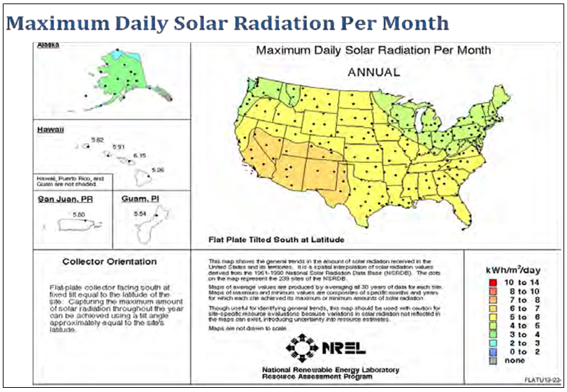
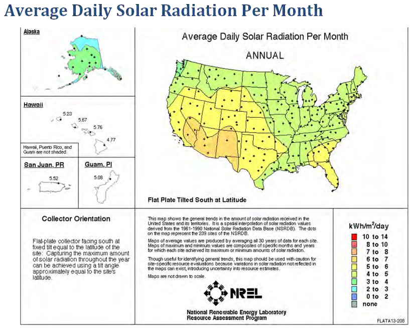
The efficiency and performance of solar water heating systems depend on a site’s solar energy resource. Solar resource is measured by the solar radiation intensity of an area, but cloud cover and latitude must also be factored into the system purchase decision. The amount of solar energy available for heating water varies by geographical location. Figures 2.1 and 2.2 show that tilted flat plate collectors located in the United States at an angle equal to the latitude receive the most sunlight in the desert Southwest and the least sunlight in the Pacific Northwest and states in the Northeast. Table 2.1 lists the maximum daily solar radiation and average daily solar radiation for selected US locations. Detailed monthly solar radiation information for a multitude of locations in the United States is available from the National Renewable Energy Laboratory at:

2.2 Cloud cover
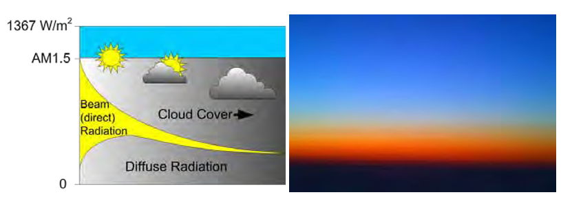
The power of solar radiation entering the atmosphere, or the “solar constant,” is 1367 W/m2 (50,169 Btu/hr/sq ft). Within the atmosphere, this power is reduced by absorption, scattering, and reflection effects to about 1000 W/m2 (36,700 Btu/hr/sq ft) on the earth’s surface if there is a clear sky (Figure 2.3). The solar radiation that reaches the earth’s surface is further reduced by clouds,
which reflect part of the radiation back into space, and absorb another part. In addition, a part of the radiation is dispersed into diffuse radiation by multiple reflections. Diffuse irradiation on the earth’s surface consists of the irradiation coming from angles different than the solar incidence angle (i.e., the actual sun position). Therefore, cloud cover reduces the total amount of irradiation (global radiation), and (due to scattering), it also changes the relation between beam and diffuse radiation. As cloud cover changes with the seasons, these effects are also seasonal dependent. The diffuse fraction of the total annual global radiation can be higher than 50%, depending on the location.
Even on a clear day a significant amount (>10%) of solar radiation is scattered due to the effects of molecules in the atmosphere. This causes the sky at daytime to appear blue and colors the sun red at sunset, when the distant light waves that enter the atmosphere are longer.
2.3 Site latitude
The latitude of the site will affect the solar radiation collected, so it is important to tilt panels based on the latitude of the installation site. The United States lies closer to the middle latitudes, which means it receives more solar energy in the summer when the sun’s path is most perpendicular to locations below. The sun slants far south during the shorter days of the winter months when the sun follows a southern path in the sky. For this reason, solar collectors should face true south in the northern hemisphere, i.e.:
2.3.1 Season of year
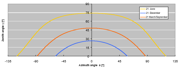
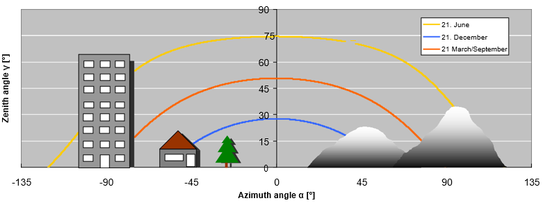
The height of the sun’s travel on the horizon varies by season of the year. In the summer, it is more directly overhead; in the winter, it is much lower. Figure 2.4 shows the different paths* of the sun over the sky for Washington, DC. The maximum incidence angle during (solar) noon for the location in this example is 75 degrees on the 21st of June (the summer solstice). The minimum incidence angle occurs on the 21st of December (the winter solstice). And the average incidence angle occurs on the 21st of March and the 21st of September (the autumnal and vernal equinoxes). For locations further north, these curves will be flatter, and for locations further south, steeper.
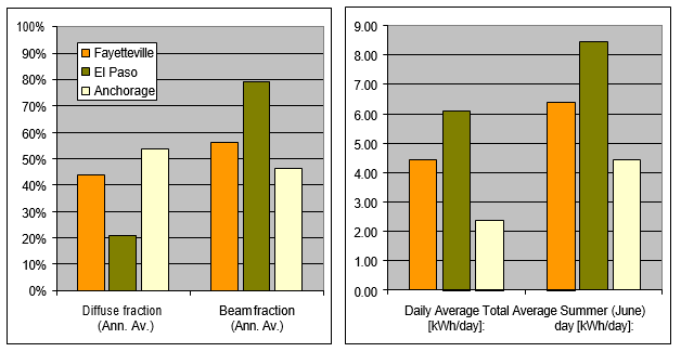
Thus, the amount of solar energy that can be collected varies throughout the year. Monthly available solar radiation values are used to determine the size of the solar collector system required to satisfy the heating demand. Figure 2.5 shows the variation of beam and diffuse radiation over the year for three locations. (The values apply to a collector surface tilted 40 degrees south facing.)
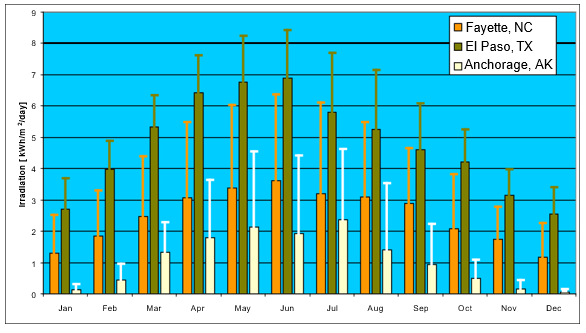
The sum of beam and diffuse radiation falling on a horizontal surface is usually called “global solar radiation.” The annual total in the figure above, 40-degree tilted south facing, for Fayette NC is~507,504 Btu/y*sq ft (~1600 kWh/y*m2); and for El Paso, TX, 697,818 Btu/y*sq ft (2200 kWh/y*m2); and for Anchorage, AK, 272,783 Btu/y*sq ft (860 kWh/y*m2). This results in an annual daily average of 1,396, 1,935, and 761 Btu/sq ft*day (4.4, 6.1, and 2.4 kWh/m2)*day respectively. The fraction of diffuse radiation is 44%in Fayette, 21% in El Paso, and 53% in Anchorage. Day and seasonal variation can be very high; a nice summer day may provide as much as 2,030.02 Btu/sq ft*day (6.4 kWh/m2)*day in Fayette and 2664 and 1459 Btu/sq ft*day (8.4 and 4.6 kWh/m2 *day) in El Paso and Anchorage and a cloudy winter day may have as little as 63.44 Btu/sq ft*day (0.2 kWh/m2*day) on average in the month of December in Anchorage (Figure 2.6).
2.3.2 Solar collector tilt
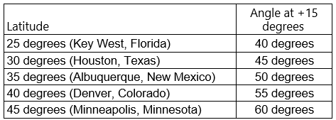
Solar systems should be designed to match the heating demands with the solar energy intensity that varies throughout the year. In the northern hemisphere, a solar thermal system will receive less solar radiation in the winter than in summer. To improve the seasonal solar energy collection, the solar collector can be tilted so that it would be more perpendicular to the sun’s path when the heating demand is greatest. Tilting of collectors (from horizontal) should be done to maximize the radiation collection skewed for usage. Thus a system that is providing heat for the winter should have a tilt angle equal to the site’s latitude, plus up to 15 degrees; a system for year round heating should have a tilt angle equal to the site’s latitude. Table 2.2 lists collector tilt angles at selected locations for maximizing winter solar energy collection.
Maximum radiation can be collected when the collector is faced due South in the Northern Hemisphere. If the system must be East or West facing, using a Westerly azimuth is more optimal than an Easterly one since the collector can take advantage of the warmer part of the day.
2.4 Orientation to path of sun
Two angles describe the orientation of the collector:
- The azimuth* angle α, also called “compass orientation”: The angle in a horizontal surface between the collector and the due south direction. Due south, towards the equator, is by definition an orientation of 0˚.
- The tilt angle β (“sky ward orientation”): The angle between the collector and the horizontal surface.
Costs for supporting structures can be saved by mounting collectors flush with an existing, suitable surface or structure. Tools (brackets etc.) are usually available from the supplier of the collector, which will suit various common surface types like tiled or sheet metal roofs, brick or wood walls etc. The fittings should provide sufficient strength to endure extreme weather conditions like wind and snow loads. It is important that the mounting and structure comply with local standards and regulations.
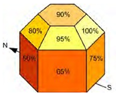
If mounted in line with an existing structure (e.g., a wall surface) the orientation may be less than optimal, in many cases. The effects of these compromises are often less than expected. This is shown in Figure 2.7. A deviation from the maximum yield tilt and orientation can be compensated for by a larger collector area, if space and costs permit.
A rule of thumb for optimum exposure to solar radiation is that a collector should face the equator (orientation of 0 degrees, due south) with a tilt angle of 0.7 times the Latitude of the location (but at least 10 degrees, or the minimum working angle of the collector). This applies to heating domestic water systems.
The optimum collector tilt angle for the usage of solar energy during winter months is higher because the average sunlight incidence angle is lower. Choosing a larger tilt angle provides a yield that is geared towards winter heat demands. The optimum collector tilt angle for the winter months is higher than the latitude, for example 50 degrees for a site at 45 degrees latitude. Deviations up to 60 degrees from these optimum angles generally will lead to a loss of solar radiation of less than 15% compared to optimum angles. Note that the annual yield also depends on many other factors such as the heat demand characteristics or the storage capacity.
Choosing a smaller tilt angle gears the yield towards the summer. Usually a summer bias increases the potential overall annual yield of a collector, but only if this extra yield can be used. Solar thermal systems are thus often sized by matching the collector yield during the summer period with the hot water heating need (called economical collector sizing), any increase in collector area will increase the fraction covered in winter, but will also increase the stagnation periods and duration during summer. Refer to Section 3.4.2 (p 33) for an explanation of stagnation.
2.5 Shading
Shading causes less radiation to reach the collector surface. The positioning decision of the collector may be influenced by anything that can cause shade on the collector surface such as mountain ranges on the horizon, nearby or tall buildings, nearby trees (in particular when carrying leaves during winter), and nearby roof construction. Local fog conditions can also cause a loss in sunlight. Shading should be avoided during the peak sun hours of the day, 9 a.m.–3 p.m.
The loss of incoming radiation due to shading must be taken into account during simulations for calculating the prospective yield and usually involves mapping the obstacles on the horizon and sky in the face of the collector orientation (Figure 2.8).
Causes of shade such as fallen leaves and snow depend on location and climatic conditions and should also be considered.
2.6 Collector placement within a building cluster
The solar collectors can be placed on buildings or on the ground. In some cases they could be placed in an elevated position over parking lots providing shade below as an additional benefit. Placement on a building is normally on the roof where a sloped or flat roof exists. Placement on a sloped roof normally creates a collector tilt similar to that of the roof. Also, the orientation may not be directly to the south. In these cases, heating energy obtained from the collector must be derated from that of an optimum placement. Such a placement normally gives a better appearance than that of tilted collectors on a flat roof. Building integrated collectors are assimilated into the original construction of the roof or can be placed slightly above the pitched roof. In either case, the collectors will use the structure framework of the roof as the main support.
The most important considerations for collector placement is to encourage integration in existing infrastructure, and to avoid shading at periods when solar radiation is plentiful and heating is needed. For large central systems the option of creating a large collector field is usually chosen. This system can be integrated with carport roofing or placed on the flat roof of a large building.
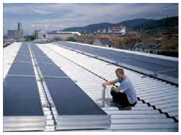
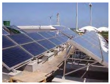
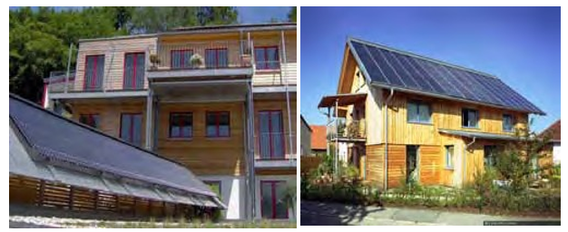
Figures 2.9 and 2.10 show examples of installed collector fields. Integration into new building structures may be more aesthetic and may provide for savings in roof cover material otherwise used. Specially constructed flat plate collectors can provide a closed, insulated surface, which may serve as a roof cover (Figure 2.11).
Collectors placed on the ground or on flat roofs need a supplemental support to generate the collector tilt to the sun. The rows of collectors must be separated by a short distance so that one row does not shade the row behind it. The distance to assure no shading on the winter solstice can be calculated by:
Separation distance = collector height X tangent of the angle (90 – latitude- 23.5)
Since the energy collected in the winter is a small percentage of the total, then the spacing between rows can be slightly reduced with only minor loss in performance. Figure 2.12 shows how the winter midday sun-angle is (usually) used to determine the angle.

Chapter: 3 Solar Hot Water Thermal System
The main components added to a conventional heating system when solar thermal energy is used are:
- collector field with collector field piping and support structure
- heat transfer fluid (water or water glycol mixture)
- a storage tank system
- pump for solar loop and other pumps for other loops
- heat exchangers to transfer heat from one loop to another
- expansion and safety devices for each closed loop
- a controller with temperature sensors in collector field and storage tank and that turns the pump on and
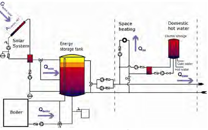
Since a solar thermal system does not usually act as the main heat source, an auxiliary (back-up) heater is necessary to cover periods of high energy demand or too little solar radiation (usually in winter). Figure 3.1 shows a schematic of a solar domestic hot water system.
3.1 Collector performance indices
Various performance characteristics are used to assess and compare solar thermal systems. The most important ones are the “solar fraction” (SF), the “specific solar energy yield” (SE), and the “solar system efficiency” (SN). The following sections discuss these indices.
To ensure that the reference quantities and energy flows can be clearly assigned, the essential parameters are entered in accordance with their definition and their “position within the system” (Figure 3.2). When selecting the proper components of a large solar hot water thermal system it is best to use analytical modeling tools such as f-Chart or TRNSYS. These computer programs can estimate annual energy collected, storage and heat exchanger effects, system heat losses, etc. Refer to Section 3.3.2 (p 23) for information regarding these modeling tools.

3.1.1 Solar fraction (fsolar or SF) and Fsave
A commonly used solar system performance measure is the solar fraction, which identifies the fractional amount of the building heating energy needed is supplied by the solar thermal system. This Design Guide defines the solar fraction for solar supported heating networks as:

Thus, a building that requires 10.24 MBtu (3000 kWh) per year to generate hot water and obtains 6.83 MBtu/yr (2000 kWh/yr) from its solar system has a solar fraction of 67%. A very similar indicator is the “f-save” ratio. This indicator shows the thermal heating energy saved by the supply of solar energy as compared to the heating energy that would have been used by a non-solar thermal (reference) system for the same purpose. For example, when a non-solar heating system (the reference system) requires 10.24 MBtu/yr (3000 kWh/yr) to provide for a certain hot water use, and the solar thermal system requires 6.8 MBtu/yr (2000 kWh/yr) auxiliary heating, then the f-save of the solar thermal system is 33% (i.e., the fraction of auxiliary energy saved compared to the reference system). The formula for f-save (thermal) is:


For both indicators it must be specified whether direct energy (heating energy demand), primary energy, or secondary energy is used in their calculations. The major difference is what is included in the building heating energy use (the reference system) and the impact of thermal system losses and supporting equipment energy use such as by pumps, etc.
Higher solar fractions mean higher energy and CO2-savings relative to the conventional energy source. However, one must also consider that the higher losses of the solar thermal system negatively affect the solar system efficiency. An economic optimum has to be found.
3.1.2 Solar system efficiency (SN)
In addition to the solar fraction, economic investigations of solar thermal systems are often affected by another parameter, the solar system efficiency (SN). The solar system efficiency describes the ratio between the annual amount of energy supplied to the heat storage unit and the global irradiation that strikes the collector surface:

3.1.3 Specific solar energy yield (SE)
The specific solar energy yield describes the annual amount of energy supplied to the heat storage unit from 11 sq ft (1 m2) of collector surface area. Compared to other calculation results, the kind of surface (absorber, aperture or gross collector area) must always be indicated for the specific yield result.

The specific solar energy yield is often said to be the crucial parameter for measuring the capacity of a solar energy system. For a correct interpretation of this parameter, the size of the system, the solar fraction and the system losses (storage and heat distribution losses) must be considered. Solar collector ratings provided by Solar Rating and Certification Corporation and the Florida Solar Energy Center use the gross area of the collector (not the net area) in their performance efficiency rating information. ASHRAE Standard 93-2010 (for testing to determine thermal performance of solar collectors) also uses the gross area of the collector.
3.1.4 Collector testing and certification organizations
Several organizations provide certification of solar collector and solar collector system performance in the United States, the most recognized of which are:
- Solar Rating and Certification Corporation (SRCC). This is the principle rating organization for solar domestic hot water collectors. The SRCC offers OG-100 certification for solar collectors and OG-300 for entire systems. OG-300 certification is for smaller residential systems.
- Florida Solar Energy Center (FSEC). Mandated by the state of Florida to perform testing of solar energy products, the FSEC is a good source for performance characteristics on both solar thermal collectors and entire solar thermal systems. Although specifically geared towards the solar industry in Florida, the FSEC is a good resource for the Southeast region as a whole. FSEC Standard 101-09, which was revised May 2009, is the institute’s solar collector certification. It supersedes FSEC Standard 102-05.
- North American Board of Certified Energy Practitioners (NABCEP). The NABCEP provides certification programs for solar electric and thermal system installers. A NABCEP-certified installer provides for an extra level of assurance as to the qualifications of the installer. However, because the solar thermal certification is a relatively recent development, NABCEP- certified installers are not especially common.
3.2 Types of hot water solar systems
3.2.1 Passive systems
“Passive” systems solar hot water systems do not have a pump or other moving parts. These heating systems rely on temperature changes in the water located in the solar collectors on the roof to move the water through the system. They are typically less expensive than systems having a pump (active systems) because they have no mechanical parts, but they are usually not as efficient. However, passive systems can be more reliable and may last longer. There are two basic types of passive systems: batch and thermosiphon.
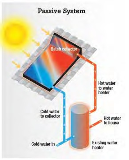
Batch or Integrated collector-storage (ICS) systems. These systems work best in areas where temperatures rarely fall below freezing. They also work well in buildings with significant daytime and evening hot-water needs. Batch collectors (Figure 3.3) or ICS, use one or more black tanks or tubes in an insulated, glazed box. Cold water first passes through the solar collector and is preheated.
The water then continues on to the conventional backup water heater, providing a reliable source of hot water. This type of collector should be installed only in mild-freeze climates because the outdoor pipes can freeze in severely cold weather.
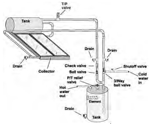
Thermosiphon systems. Thermosiphon systems (Figure 3.4) move water through the system due to density differences (warm water rises as cooler water sinks). Neither pumps or electricity are used. However, the collector must be installed below the storage tank so that warm water can rise into the tank. These systems are reliable, but contractors must pay careful attention to the roof design because of the heavy storage tank. Although they are usually more expensive than ICS systems, they can be used in areas with less sunshine.
Passive solar water heating systems are used on individual buildings or for a single heating demand. They are not for central heating systems that service several buildings. They are also inefficient in cooler climates. Since the purpose of this design guide is to focus on systems that can serve multiple buildings, these systems will not be further discussed.
3.2.2 Active systems
Solar water heating systems that rely on electric pumps to circulate fluid through the collector are called “active systems.” Active systems are generally categorized into two types: direct and indirect, which simply means that water in the storage tank is either directly filled using the hot water flowing from the solar collectors (one loop) or indirectly using two water circulating loops separated by a heat exchanger. The latter type is normally used in locations where outdoor winter temperatures below freezing may occur. These systems use an anti-freeze solution such as a water glycol mixture as a heat transfer medium that circulates through the collectors to avoid freezing.
Direct circulating active system (no anti-freeze). These systems use pumps to transfer the sun’s energy directly to potable water by circulating this water through the collector tubing and storage tank; no anti-freeze solution or heat exchanger is used. The pumps circulate water through the collectors, into the building, and back again. They work well in climates where it rarely freezes.
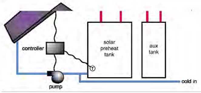
A direct active system (Figure 3.5) has one or more solar energy collectors installed and a nearby storage tank. The system uses a differential controller that senses temperature differences between water leaving the solar collector and the coldest water in the storage tank. When the water in the collector is about 15 to 20 °F (-9 to -7 °C) warmer than the water in the tank, the pump is turned on by the controller. When the temperature difference drops to about 3 to 5 °F (-16 to -15 °C), the pump is turned off, so the stored water always gains heat from the collector when the pump operates. A flush-type freeze protection valve installed near the collector provides freeze protection. Whenever temperatures approach freezing, the valve opens to let warm water flow through the collector. The collector should also allow for manual draining by closing the isolation valves (located at a height above the storage tank) and opening the drain valves. Automatic recirculation is another means of freeze protection. When the water in the collector reaches a temperature near freezing, the controller turns the pump on for a few minutes to warm the collector with water from the tank.
Another type of direct active solar water heating system is called “a drainback-system” (Figure 3.6), which is also designed for cold climates. This type of system typically uses regular water as a heat transfer fluid, and is designed to allow all of the water in the solar collector to “drain back” to a holding tank in a heated portion of a building. When no sunlight is available for heating, the solar pump turns off and the water flows into the drainback tank by means of gravity. Since these systems use water, they can be designed with or without a heat exchanger.
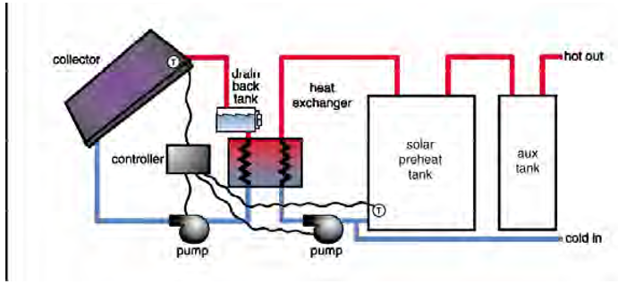
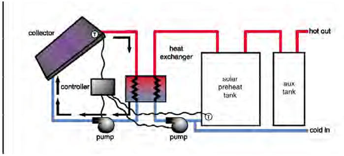
the collector to the water in the storage tank. These systems offer excellent freeze protection, tolerate hard water well, and have high maintenance requirements.
Indirect circulating active system (anti-freeze used). This system operates similar to the direct active system except that there are two circulating heat transfer fluid loops. In the first (solar primary) loop non-freezing, heat-transfer fluid such as a water-glycol mixture circulates through the collector field. A heat exchanger transfers the heat from the water-glycol mixture into the potable water. The heat exchanger can either be directly integrated into a storage (internal heat exchange) or the storage can be connected to a second loop (solar secondary loop) via an external plate heat exchanger (Figure 3.7). These systems are popular in climates that are prone to freezing temperatures.
If the solar collector is extremely well insulated and is not prone to freezing like an evacuated tube collector, water can be the heat transfer fluid. By using water the heated water from the collector can be sent directly to the storage tank; no heat exchanger is needed. Figure 3.8 shows the portion of this system before the storage tank (and, if used, before the heat exchanger).
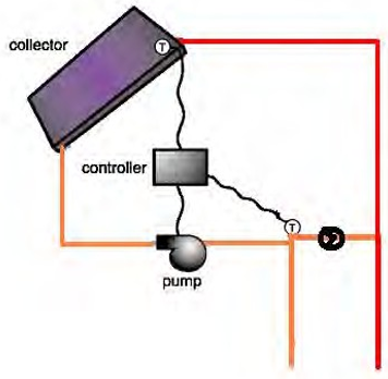
Indirect circulating solar water heating systems used on individual buildings or groups of buildings are consistent with the US Army’s needs. They can easily be applied to central heating systems for domestic hot water and building heating. Since the purpose of this design guide is to focus on systems that can serve multiple buildings, these systems will be emphasized in further sections of this course.
3.3 Solar thermal energy collectors
The collector is a key part in a solar thermal heating installation. The following sections discuss the working principle of collectors, and the most common collector types. Most relevant for the application in domestic hot water and space heating systems are glazed flat plate and evacuated tube collectors. A collector should be selected based on the quantity and quality (temperature) of the demanded heat.
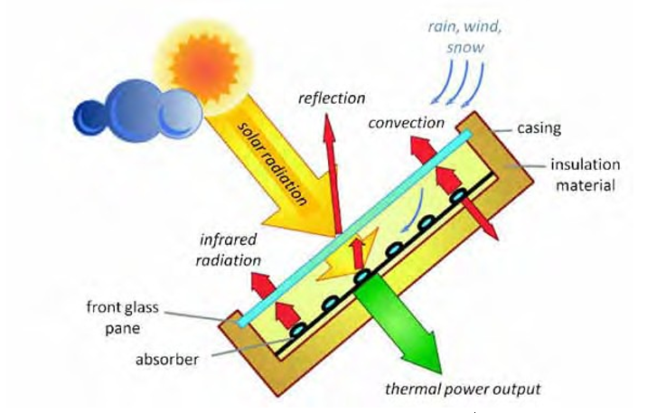
In principle, heat gain and loss mechanisms in different collector types are the same. In general, one differentiates between optical losses (reflection, absorption) and thermal heat losses due to heat transfer mechanisms (conduction, convection and radiation). Figure 3.9 shows the mechanisms for a flat plate collector (FPC).
3.3.1 General construction
Figure 3.9 shows how heat from the sun is collected by the absorber and is carried away by the fluid flowing through the tubes attached to the absorber. Since these collectors are located outside and normally in a cooler environment, the heated absorber can lose heat its surroundings. To reduce this heat loss, a cover is placed over the absorber and the sides and back of the absorber are insulated. The cover must allow solar radiation to penetrate and, since glass is typically used, some of this radiation will be reflected and radiated out to the atmosphere. The following sections will provide a brief overview and details of the solar collector parts.
3.3.1.1 Absorber
The function of the absorber is to effectively convert solar radiation into heat. The absorber surface is often coated to maximize this energy collection. The absorber coating is thus designed with a high absorption coefficient, a, for the sun’s radiation spectrum (typically a = 0.92 to 0.96).
Absorptivity is the fraction of incident sunlight captured (not reflected) by the absorber. The reflectance is the complement of the absorption and is given by: ρ= 1 – α. For best performance, the absorber should have a low emission coefficient ε (typically, ε = 0.05 to 0.1) for infrared radiation to keep the losses from long wave radiation emission low as the collector heats up.
Emissivity is the ratio of radiant heat loss off the absorber relative to that of a perfectly black surface (“blackbody”). Most common materials, such as black paint, have an absorptivity equal to the emissivity, and the second law of thermodynamics requires that all materials have a=e at a given wavelength of incident light. However, special surface treatments (semiconductor coatings, blackened nickel layer) have an absorptivity in the short-wavelength solar spectrum that is much higher than emissivity in the long-wavelength infrared radiant heat loss spectrum. Such surfaces are called “selective surfaces” and improve the performance of solar collectors, especially when operating at elevated temperatures where radiant heat loss is more important.
Absorber coatings that possess high absorptivity and low reflectance are called “selective absorbers.” Figure 3.10 shows this selective effect where the absorption/reflection characteristics of a selective surface are identified at various wavelengths of the solar spectrum. These wavelength values are taken with an atmospheric thickness of 1.5 of the thickness taken directly above (AM = 1.5). This is important since the atmosphere affects the spectral nature (wavelength distribution) of the solar radiation, and properties reported at AM=1 refer to one thickness of atmosphere. If the sun is not directly overhead, the sun’s rays will have to go through more than one thickness of atmosphere. For example, AM = 1.5 corresponds to a zenith angle of around 48.2 degrees, and AM=0 refers to the wavelength outside of the earth’s atmosphere.
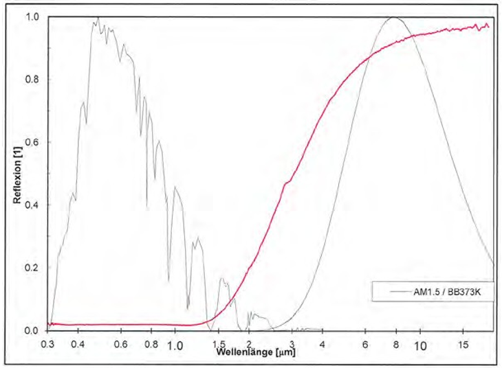
spectral reflectivity (Reflection) of a s elective absorber is indicated by the red line.
For spectral irradiance originating from the sun the solar constant (1.367 W/m2) is defined as AM = 0. AM = 1 is defined as the spectral irradiance on a horizontal plane (zenith angle = 0°). AM = 1.5 is equal to a zenith angle of around 48.2 degrees and the global radiation accounts for 36,700 Btu/hr/sq ft (1000 W/m2). (Tables of these standard spectra are given in ASTM G 173-03. The extraterrestrial spectral irradiance (i.e., that for AM0) is given in ASTM E 490-00a).
3.3.1.2 Transparent cover
The purpose of the transparent cover is to reduce the convection losses from the absorber, while allowing the maximum amount of radiation to reach the absorber. The cover must also provide the mechanical strength to protect the absorber from the environment.
Special solar glass with low iron content is used. It is occasionally called “water white glass” and its typical transmittance is t = 0.89 to 0.91 for the wavelength range of the solar radiation. This can be enhanced to t = 0.94 to 0.96 when anti reflective coatings are applied. This glass should be tempered to reduce breakage by impact.
3.3.1.3 Housing
The housing of a collector must provide the necessary mechanical strength to protect the absorber and the insulation to minimize heat loss to the environment. It must withstand wind and snow loads that occur in the area where the collector is installed. It also must be tight enough against rain penetration. These features need to be ensured over the entire lifetime of the system (20 to 25 yrs). Housings are typically made from aluminum sheet stock or extruded sections, galvanized and painted steel, molded or extruded plastic parts, or composite wood products.
3.3.1.4 Insulation
Insulation is added behind the absorber plate and on the sides of the collector to reduce thermal heat losses. The insulation must use a minimum of binders because it is intended for high temperatures (up to about 400 °F [204 °C] for flat plate collector stagnation); otherwise, the binders will outgas and form a film on the underside of the collector glazing blocking solar radiation.
Common insulating materials include, for example, mineral fiber, ceramic fiber, glass fiberglass, and plastic foams. Sometimes polyurethane foam is used, though its resistance to temperature and moisture is limited so it should not be allowed to contact the absorber plate inside the collector. The insulation provides low heat conductivity, some mechanical strength, and temperature and fire resistance.
3.3.2 Types of solar thermal energy collectors
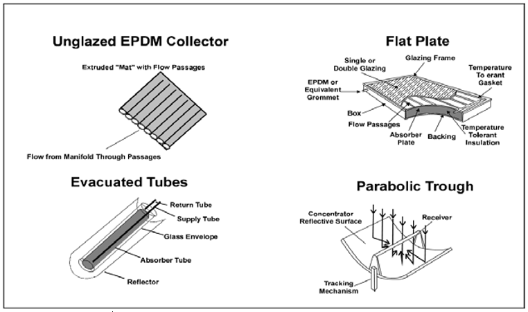
Figure 3.11 shows the four different types of solar hot water collectors. The type of collector chosen for a certain application depends mainly on the required operating temperature and the given ambient temperature range. Due to the design and simplicity of design each type has a maximum temperature that they are best suited to provide:
- Unglazed EPDM* collector – below 90 °F (32 °C)
- Flat plate – below 160 °F (71 °C)
- Evacuated tube – up to 350 °F (177 °C)
- Parabolic trough – up to 570 °F (299 °C).
In the Army, the major hot water requirements are heating for domestic hot water, reheat for humidity control, and building heating. These requirements need a hot water source with a temperature of at least 140 °F (60 °C). This eliminates the unglazed EPDM collector from consideration. The ability of the parabolic trough greatly exceeds these requirements and thus would be a poor selection due to its high cost. This leaves the flat plate and the evacuated tube collectors as appropriate choices for Army applications. Both types of collector would be a good choice for most Army installations, but several factors could influence the selection:
- Cost (from RS Means Green Building Project Planning and Cost estimating, 3rd )-
- Flat plate – ~$17/sq ft = ~129€/m2
- Evacuated tube – ~$24/sq ft = ~182€/m2
- Freeze Protection
- Flat plate – Use non freeze liquid (glycol solution)
- Evacuated tube – some are well insulated so they could use water as collector fluid with the strategy of cycling warm water into the collector from the storage tank if the collector fluid gets too
- Stagnation Issues. Stagnation is caused when the flow through the collector stops and the solar energy heats the collector fluid to extremely high temperatures causing the collector fluid to boil. At what temperature this boiling occurs is dependent on the fluid and the operating pressure on the system. This boiling will push a portion of the collector fluid from the pipes in the collector and can hamper later collector performance. Section 4 (p 32) discusses this topic in more detail.
3.3.2.1 Unglazed flat plate
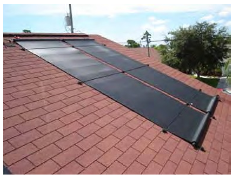
Unglazed flat plate collectors (Figure 3.12) are usually plastic collectors that are rolled out onto a roof and that are generally used for low temperature heating of such things as swimming pools or preheating of domestic hot water. Due to the absence of a glass cover they have no optical losses and therefore are most suitable for low temperature applications since heat losses increase more with higher temperatures compared to the other collector types. The manufacturers use plastic materials that reduce production and installation costs. Extensive testing and analysis have so far confirmed that the technology meets or exceeds reliability goals. They are generally less expensive, but less efficient than standard solar water heating collectors used throughout all seasons.
3.3.2.2 Glazed flat plate
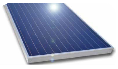
Flat plate collectors (FPC) are essentially insulated boxes that have a flat dark plate absorber that is covered by a transparent cover (Figure 3.13). The solar energy heats the absorber and heat is carried away by a heat transfer fluid that flows through riser tubes that are connected to the absorber. The riser tubes are attached to the absorber in a parallel pattern or they meander from one side to the other.
The cover (usually a sheet of glass) is held in place by a frame above the absorber. The frame also seals the collector at the sides and at the back. It must provide mechanical strength and rain tightness, and must be designed to enable simple roof- and facade attachment or even integration into these building elements. The back and sides of the collector are insulated. Flat plate collectors are usually installed in stationary systems, i.e., they do not rotate to follow the path of the sun. The advantages of flat plate collectors are their simple, robust, low-maintenance design, and their large and effective aperture area.
Flat plate collectors are most commonly used for commercial or residential domestic hot water systems. These collectors generally increase water temperature to as much as 160 °F (71 °C). Special coatings on the absorber maximize absorption of sunlight and minimize re-radiation of heat. These collectors are prone to freezing and in climates where this can occur a mixture of about 60% water and 40% polypropylene glycol is used as the collector fluid (heat transfer medium).
3.3.2.2.1 Design considerations
Flat plate collectors similar to today’s design have been manufactured for over 30 yrs and experience has been gained as to the proper materials to use for best performance and long life. The casing is typically made of aluminum. The absorber plate is made of copper or aluminum; steel is seldom used. To maximize the absorption of the solar energy the absorber plate is typically coated with black chrome, which is a selective covering providing good absorption and weak reflection of solar radiation.
Copper is normally used as the flow channel (tubing) through which the heat transfer fluid flows. It must be well bonded to the absorber plate for good heat transfer. The tubes are commonly placed in parallel rows (as shown in Figure 3.13) where the flow is released in a header at the top of the collector and is collected at the bottom.
Another tube arrangement is for the flow to meander across the surface of the absorber in a back and forth serpentine fashion. In this case the volume of heat transfer fluid spends more time on the collector surface and a greater temperature increase occurs. To obtain proper heat transfer from the absorber to the collector fluid the spacing between the runs of tubing cannot be too great and a tube interval of 4 to 5 in. (102 to 127 mm) is typical. In all cases, the tubes in a collector need to be placed so that the fluid can completely drain from the collector by gravity.
The housing around the absorption plate is mainly to minimize the heat loss to the environment and to provide a weather tight enclosure to prevent corrosion and other types of deterioration. Behind the absorption plate, rock or glass wool, or an insulating foam may be used an the insulating material. Typically a depth of 1-1/2 to 3 in. (38 to 76 mm) of insulating material is used. The insulating material must have the thermal stability to withstand the high temperatures that occur during times of collector stagnation. A glass cover is placed above the absorption plate that allows the solar radiation to pass through while limiting heat loss. Plastic covers deteriorate over time and are not recommended. Double pane glass covers retard the transparency to the solar radiation and thus are not commonly used. For sealing materials, EPDM or silicone rubber type materials should be used as the seal between the casing and the glass cover; adhesives should be silicon based and openings for pipes should be sealed with silicon based products.
3.3.2.2.2 Applications
Flat plate collectors are used mainly for producing domestic hot water and, in some cases, where building space heating is also accomplished. Standard flat plate collectors typically perform best providing hot water below 160 °F (70 °C). There are high performance flat plate collectors (those with a double, anti reflective cover) that perform well providing up to 200 °F (93 °C) hot water.
These are seldom used due to their high cost. Above that temperature, the efficiency drops significantly due to the higher temperature difference between the collector fluid and the ambient air.
It is possible to reduce the thermal heat losses by avoiding convective losses such as by using vacuum tube collectors. The following section discusses this option.
3.3.2.3 Evacuated Tube
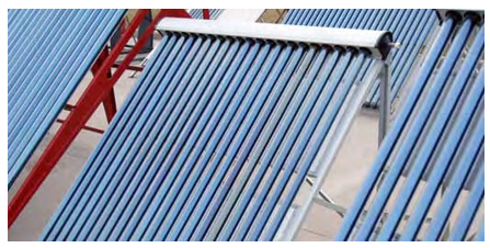
Evacuated tube collectors (Figure 3.14) can be designed to increase water/steam temperatures to as high as 350 °F (177 °C). They may use a variety of configurations, but they generally encase both the absorber surface and the tubes of heat transfer fluid in a vacuum sealed tubular glass for highly efficient insulation. Evacuated tube collectors are the most efficient collector type for cold climates with low level diffuse sunlight.
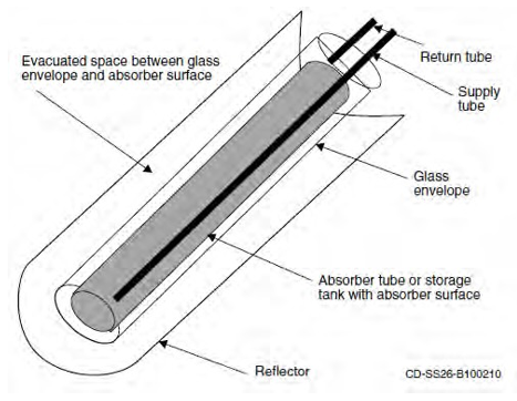
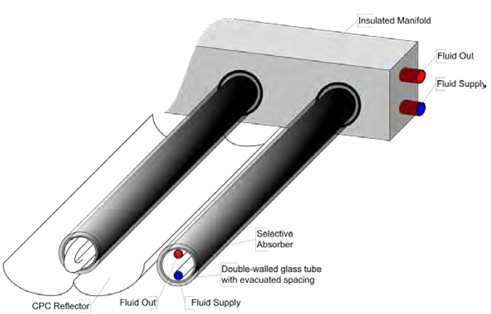
There are three types of evacuated tube collectors: (1) direct flow, (2) heat pipe, and (3) Sydney tube type. The direct flow type has the heat transfer fluid flowing through copper tubes attached to a absorber plate mounted inside the evacuated tube. The heat pipe type uses a heat pipe attached to the absorber plate. The heat pipe transfers the heating energy to the condensing section of the heat pipe where the collector fluid is warmed. This occurs in the header where the evacuated tubes are connected. The last type has an evacuated tube called a Sydney tube (Figure 3.15) that encapsulates a heat conductor sheet (absorber) with heat transfer fluid carrying tubes. The Sydney tube slides over the absorber section and locks into the collectors header forming a tight seal. Within the Sydney tube the space between inner and outer glass tube is evacuated. The selective coating is sputtered onto the outside of the inner glass tube. A heat conductor/transfer sheet is located inside the inner glass tube that conducts the heat from the glass into the U-form tubes carrying the heat transfer fluid. The Sydney tube type collector’s performance can be enhanced through the use of a compound parabolic concentrator located behind each tube. This device will reflect the solar radiation that passes between each evacuated tube back to the underside of the cylindrical absorber in the collector tubes. There are various other construction methods like flat or round absorber, and single- or double-walled glass.
All evacuated tube collectors have the following in common:
- A collector consists of several evacuated glass tubes positioned in parallel and are joined by an insulated manifold at one end for the supply and removal of the heat transfer fluid (Figure 16).
- Due to the vacuum insulation (pressure < 10-2 Pa) heat loss caused by conduction and convection are minimal.
- The upper end of the tubes is connected to the “header.”
- The tubes are circular to withstand the outside pressure.
3.3.2.3.1 Design considerations
Evacuated tube collectors have only insulated tubes and a pipe header to which the evacuated are connected. The collector fluid tubes use copper and typically black chrome is used as the selective absorber coating. The pipe header is insulated and has a protective cover.
3.3.2.3.2 Applications
This type of collector is used when there is a need for hotter water than would be necessary for domestic hot water heating. Hotter water is needed for applications that have cooling in the summer as a requirement and in some cases where building heating is a major need. Solar assisted cooling uses an absorption or adsorption chiller, which requires hot water temperatures in the range of 130 to 350 °F (55 to 180 °C).
An evacuated tube type collector may also be chosen as an alternative for a flat plate collector in areas where winter time freezing occurs. In this case, water would be used as the heat transfer fluid in the collector and warm water would be pumped into the outside piping and collector when freezing of those components is threatened. This would required a small amount of heated water due to the insulating quality of the evacuated tubes. As a result, the cost and inferior heat transfer characteristics of a water glycol mixture is avoided. Also the a hotter water could be produced in the collector providing a lower heat transfer fluid flow thereby reducing distribution pipe and storage tank sizes. Also, the heat exchanger between the collector and the storage tank could be avoided thus reducing the required leaving collector temperature. As a total system, the evacuated tube collector could have a total cost competitive with a flat plate collector system. The use of evacuated tube type collectors obviates most of the stagnation concerns associated with an anti-freeze heat transfer fluid.
3.3.2.4 Concentrating Collectors
These collectors use curved mirrors to focus sunlight onto a receiver tube (sometimes encased in an evacuated tube called CPC or compound parabolic collectors) running through the middle or focal point of the trough (Figure 3.17). They can heat their heat transfer fluid to temperatures as high as 570 °F (299 °C). Such high temperatures are needed for industrial uses and for making steam in electrical power generation. Because they use only direct-beam sunlight, parabolic-trough systems require tracking systems to keep them focused toward the sun and are best suited to areas with high direct solar radiation like the desert areas of the Southwest United States. These collector systems require large areas for installation, so they are usually ground mounted. They are also particularly susceptible to transmitting structural stress from wind loading and being ground mounted helps with the structural requirements.
Parabolic-trough collectors generally require greater maintenance and supervision and particularly benefit from economies of scale, so are generally used for larger systems. Because of their higher cost and greater maintenance needs this type of collector is not recommended for US Army heating needs in their standard buildings.
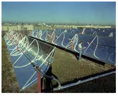
Colorado.
3.3.3 Hot air collectors
Air collectors currently do not have a large market share (e.g., 0.5% in Germany in 2009). Nevertheless they can be considered as an alternative in certain situations (e.g., space heating, when an air heating system is used). As the type name indicates air collectors use air as the heat transfer medium (instead of water and glycol). This has some advantages:
- Air does not freeze or evaporate and air does not degrade when exposed to high temperatures. Freezing and stagnation thus does damage the system. Air collectors are usually intrinsically safe.
- Fresh air may be used directly as heat transfer fluid; a volume of air has no cost and is non- toxic. Leakage in the system does not cause damage to the system nor the
On the other hand some disadvantages are:
- Air has lower heat transfer attributes and a lower heat capacity (a factor of 4 times lower compared to water and glycol).
- Higher driving power by a fan is needed for a comparable mass flow [kg/h] to a fluid glycol.
- Larger cross sections for conduction pipes are necessary.
- If water is to be heated, an additional heat exchanger is needed.
3.3.4 Solar hot water collector efficiency
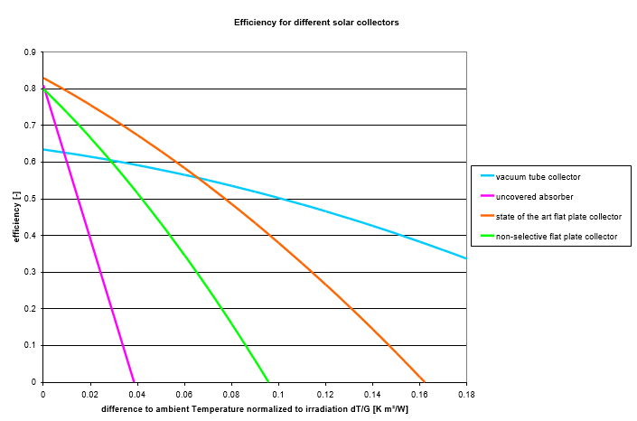
The efficiency of the solar collector is directly related to heat losses from the surface of the collector. Heat losses are predominantly governed by the thermal gradient between the temperature of the collector surface and the ambient temperature. Efficiency decreases when either the ambient temperature falls or when the collector temperature increases. This decrease in efficiency can be mitigated by increasing the insulation of the unit by sealing the unit in glass (for flat collectors), or providing a vacuum seal (for evacuated tube collectors). Figure 3.18 shows efficiency curves of these collectors. When comparing collector efficiencies, it is important to assume the same type of area (net vs. gross), and the same irradiation level.
The thermal performance of solar hot water collectors is characterized by:
- The power curve as shown in Figure 3.18, parameters: η0, a1 and a2.
- Incidence Angle Modifier (IAM) because of the optical efficiency of the collector.
- Thermal capacity (Ceff), which is the measure of thermal response to heating and cooling.
- The quantity of heat input into the collector to heat it by -457.87 °F (1 °K). This information would be available from the collector manufacturer. This value is used in the solar collector simulation computer programs as it relates to the small time steps in the program to the estimated heat removed. The larger the Ceff, the more energy that will be lost when switching off and on the solar heat transfer pump, which can happen as the weather changes during the day.
3.3.4.1 Power curve
For the power curve, collector performance is measured at different operating temperatures and with perpendicular insolation of G > 29,360 Btu/hr/sq ft (800 W/m2). The collector’s performance is represented by:
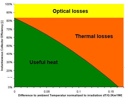

Figure 3.19 shows the power curves of four low* temperature collectors. A “rule of thumb” is to select a collector type that achieves an efficiency h ~ 50% for the working temperature range.
For use in water and low temperature space heating, both flat plate collectors (with solar glass and selective coating) and evacuated tube collectors are applicable. Both have certain advantages in specific applications especially when freezing, leaving water temperature, available space and installation cost are concerns. For applications with large collector fields, these two collector types should always be considered, and the final decision to select one technology over the other should be based on annual simulation results.
3.3.4.2 Incidence angle modifier
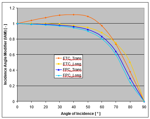
The IAM [-] describes the modification of the conversion factor h0 of the collector for non- perpendicular solar incidence angles. By definition, an IAM equal to 1 is for normal incidence. The IAM has a significant effect on the performance of stationary installed collectors as the incidence angle changes throughout the day and the year. Incidence angles less than 50 degrees do not have a significant effect on the solar thermal collector efficiency while an Incidence angle of 90 degrees is equal to a total reflection of the sun rays. Figure 3.20 shows the IAM curves of a typical FPA and a typical ETC.
The longitudinal IAM (i.e., in the direction parallel to the tubes for the ETCs) of the ETCs is similar to the flat plate collector’s while the transversal IAM of most ETCs shows a characteristic increase at intermediate angles.
Collectors with a flat absorber surface, which includes some types of evacuated tubes, only have 100% efficiency at midday. Other evacuated tube collectors collect solar radiation in a perpendicular fashion over a longer period of the day since the collecting absorber surface is cylindrical. This feature can be enhanced by placing an optimally designed reflective compound parabolic concentrator (CPC) mirror behind the collectors, causing the sunlight to strike the collector at a perpendicular angle for a great percentage of the day. This provides most of the advantages of tracking systems while avoiding their high costs. The advantages of the CPC ETC include:
- longer usable daylight time.
- more continuous power in the course of the day.
- high target temperatures over the entire day.
- higher daily and yearly energy yields.
3.3.4.3 Thermal capacity
The thermal capacity ( Ceff ) of the collector has an effect on the system performance. Every time the collector heats up, energy is absorbed by the collector. This energy is not fully recovered as useful energy. In simulations, this factor is taken into account when calculating the annual energy yield. The thermal capacity ( Ceff ) of the collector is expressed in kWh per m2 collector area per degree K. The influence of this parameter is comparably small. Nevertheless, the lower the thermal capacity of the collector, the better.
3.4 Heat transfer fluid
As the solar collector heats up, the fluid in the collector increases in temperature. This fluid is then moved out of the collector so the heat can be extracted for some useful purpose. Larger solar systems either use the heat immediately, or use heat stored in a tank of heated fluid. When the solar system is located in a freezing climate, the fluid flowing through the collector is often an anti- freeze solution. When storing heated fluid in a tank, water is often the preferred medium (to reduce cost). If this is the case, a second fluids is used and flow through a heat exchanger is required to transfer the heat from the collector to the storage tank. There also may be a third fluid, potable water, which is used directly for domestic purposes, in which case another heat exchanger would be required. The heat transfer fluids used in a solar hot water system are very important and must meet a number of requirements to ensure good performance:
- a high heat capacity and conductivity allowing efficient heat transportation from the collector.
- anti-corrosive-protection, if mixed or corrosion prone materials are present in the collector.
- non-toxicity and environmental-friendliness.
- low viscosity for easy pumping of the fluid.
- low cost and availability.
Except where freezing is a concern, water is the fluid of choice in solar energy hot water systems. It has a low cost, is plentiful, and is compatible with the materials used in these systems. Water also has high heat capacity, good conductivity, a low viscosity, and can withstand the hot temperatures that are experienced during stagnation periods of time. Passive solar systems normally use water in the solar collector. Water is also often used in evacuated tube collectors. In freezing climates an anti-freeze liquid must be used in flat plate collectors.
Water used for domestic hot water is a potable water source that must be kept safe to drink and not be contaminated by chemicals. Because of this, large systems must have at least two fluid circulating systems, one that flows through the solar collector, and another that is heated and dispensed as domestic hot water. A heat exchanger is placed between the two piping systems for the movement of captured heat from the collector heat transfer fluid to the domestic water. Figure 3.6 shows such a system. Separating the collector fluid from the domestic water allows for water treatment to prevent corrosion of the piping and collector materials. To protect the potable water a double wall heat exchanger must be used when the heated fluid is not-potable. This separation also allows for an anti-freeze solution to be used in the solar collectors if needed.
3.4.1 Anti-freeze fluids
The typical anti-freeze solution is a mixture of water and propylene glycol, but a water/ethylene glycol solution, silicon oil, hydrocarbon oil, or refrigerant could also be used. With the water/propylene glycol fluid the percent glycol should be 40% or less. A 40% solution begins to freeze at –11 °F; below that temperature, an ice slurry develops that does not readily freeze solid causing pipes to burst. A glycol solution greater than 50% is not recommended due to a higher viscosity and lower heat capacity. Systems using glycol should be aware that it has a greater tendency to seep through piping joints than water and thus the piping system should be sealed with care and checked for leaks at scheduled intervals. Glycol is not compatible with zinc so galvanized pipes should not be used.
The use of automatic water makeup to heat transfer fluids selected to be an anti-freeze should be avoided. This is because the water makeup will dilute the anti-freeze mixture and making the fluid more likely to freeze when exposed to cold outdoor temperatures. The anti-freeze fluid should be periodically checked to assure proper performance.
3.4.2 S tagnation
The heat transfer fluid used in the collector must also withstand the high stagnation temperatures. Stagnation occurs when the heat transfer fluid stays in the collector too long and a high temperature is reached greater than the normal due to the heat from solar radiation. This could happen when there is a pump or control failure, when the heating demand of the users and the storage tank are satisfied or when the system is down for maintenance. Under normal operation the heat transfer fluid is under a pressure to avoid vaporization. Most collector systems are designed to operate at pressures below 125 psig (833 kPa). This is to allow the use of standard piping components (class
125) and avoid using more costly components. Since the solar collector is generally placed at a higher elevation than other parts of the system the static head of the fluid column must be added to the operating pressure in the collector when determining the pressure on components. This means pressures at or just below 75 psig (500kPa) are common in the solar collector. At this pressure, a 60/40 mixture of water/glycol will begin to vaporize at 320 °F (160 °C). If the pressure is dropped to 45 psig (310 kPa), then vaporization would begin at a temperature of 284 °F (140 °C). Vaporization of water at these pressures is 307 °F and 275 °F (153 and 135 °C), respectively.
When vaporization begins to occur, the resulting gas displaces the liquid in the collector and to some degree in the nearby piping. This displaced fluid should be directed to a recapturing tank so that it can be used again to fill the system when the temperature cools down. There are safety valves in the piping system that must be certified for the highest temperature that may occur. They should be placed on connections to the lines leading to the recapture tanks.
The disadvantages of frequent vaporizations are:
- Water/glycol mixtures will have a shorten life when exposed to at temperatures in the 300 °F – 320 °F (149 – 160 °C) range.
- Anti-corrosion additives and contaminants may stick to the interior of pipes and absorbers flow channels.
- Operating personnel need to spend time refilling the system.
All glycol systems should use the Pressure Stagnation Protection (PSP) method. This method allows over sizing of the pressure relief valve to 150 psi (1034 kPa), which allows the system pressure to rise with stagnation temperature. This protects the fluid from overheating and preserves the properties of the glycol by keeping it in a liquid form at all times.
Since glycols begin to break down and start to become corrosive when heated to temperatures greater than 240 °F (116 °C). One way to avoid this condition is to send excess heat to a nearby low priority heat user such as a swimming pool when the temperature in the storage tank is satisfied. Such a connection to a swimming pool is established using another heat exchanger with redundant, multiple pumps. Another solution may be to route external fluid to air heat exchangers, or in some cases, to a ventilated recooling device. For smaller applications (up to several hundred m2) it is sufficient to design the solar loop expansion vessel in a way that both the additional volume of the heat transfer medium (due to the decreasing density), and the volume of the evaporated heat transfer medium (in case of stagnation) can be absorbed.
3.5 Piping arrangements
3.5.1 Collector piping alternatives
It is advised to choose collectors that feature a good emptying behavior during stagnation. This will reduce the strain on the heat transfer fluid and reduce the steam production of the collector field.
During periods of stagnation, it is likely that steam will develop in the collectors. The steam will push the fluid out of the collectors. The fluid will later be sent back into the collector field when the collector field is cooled down again.
Tables 3.1 to 3.9 list a selection of collector designs. The pipe manifolds are shown in relation to the arrangement of the tubes attached to the collector absorbers. Both flat plate and evacuated tube collectors are addressed. An attempt is made to assess the different absorber piping designs with respect to:
- steam producing power (SPP) (a low SSP is a positive property with respect to a smaller expansion vessel needed).
- glycol strain (a low glycol strain is a positive property).
- air vent possibility (a good air vent behavior is a positive property).
For the designs listed in Tables 3.1 to 3.9, real measurements of the SPP were carried out on sample collectors. For the other designs, estimations are provided that are deduced from the experience made in the investigations. In these tables, note that:
- A question mark “?” in the tables means that even no rough estimation on the expected behavior can be given. The assessment is very rough and the given collection of piping designs is not complete.
- ETC = Evacuated tube collector.
- FPC = Flat plate collector.


There are two methods connecting a row of collectors together – with an external manifold or an internal manifold. The external manifold uses a supply and return header and all the collectors in the row have supply connections to the supply header and also have a flow outlet connected to the return header. The internal manifold type connection has the supply pipes of each collector connected to the next collector. The same applies to the return side of the collector piping. The piping of the collector is similar to that listed in Table 3.9. Internal manifolds offer the following advantages:
- less piping reducing costs and heat loss
- more attractive
Disadvantages of internal manifolds are that they:
- make it more difficult to achieve a drainable system
- make it difficult to balance collector flow for a long row of collectors
- make it hard to remove a single collector
- create more significant expansion and contraction issues for a long
3.5.2 Solar System piping arrangements
Large solar systems serving multi-buildings typically have several heat transfer loops. First, there is one with the fluid flowing through the solar collector (solar primary loop). This one may contain an anti-freeze solution. Second, there is one that circulates from the heat exchanger with the collector fluid to the thermal storage tank (solar secondary loop). Third, may be a circulating fluid that heat the domestic hot water. Finally, there may be a circulating system going to a district or building heating system. Normally circulating systems use water as their heat transfer fluid. The types of piping systems can be characterized as:
- Solar supported local heating system with a two-pipe network:
- two-Pipe Networks with Decentralized Domestic Hot Water Storages
- two-Pipe Networks with Decentralized Heat Transfer Units
- Solar supported local heating system with a four-pipe network:
- four-pipe networks with centralized energy storage and centralized domestic hot water storage
- four-pipe networks with centralized energy storage and decentralized domestic hot water storage
- Solar supported district heating network with direct interconnection of a centralized solar thermal system:
- solar thermal plant directly feeding the supply line of an existing district heating network
- solar thermal plant directly preheating the return line of an existing district heating
3.5.2.1 Two pipe networks
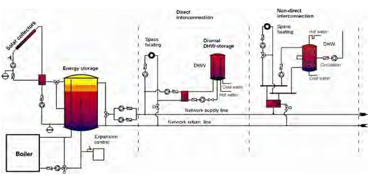
In two-pipe networks, the heat supply to the heat sinks (buildings), including both domestic hot water and space heating, is by means of a pair of pipes. Domestic hot water is heated in a decentralized manner for the individual consumers using continuous flow water heaters, or by means of decentralized DHW storages using the charge-store principle. The two-pipe network shown in Figure 3.21 consists of centralized energy storage and decentralized heat transfer units for each building or unit connected to the network.
The energy storage is the central point for all heat flows and acts as a hydraulic gateway. To guarantee a reliable supply of heat with this design, it is essential that adequate reserves are permanently stored in the upper region of the energy storage (stand-by volume) so as to cover peak demand.
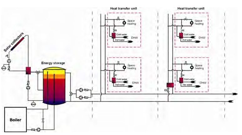
Domestic hot water is heated in a decentralized manner using continuous flow water heaters (usually via plate heat exchangers – no additional storage needed).
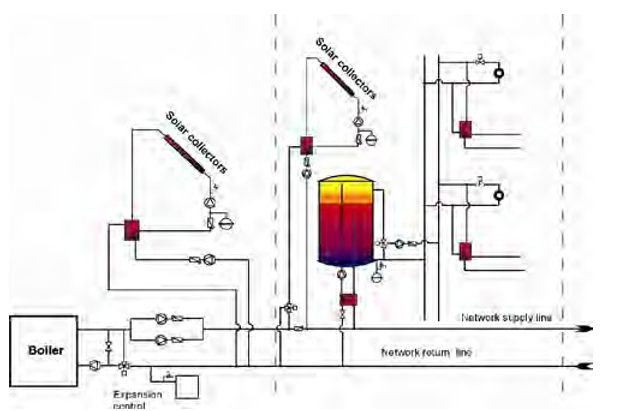
Two-pipe networks in combination with decentralized heat transfer units are ideally suited for use in compact unit blocks (medium to high energy densities). For less energy dense clusters of buildings (lower heating requirements per length of heat distribution pipe), a two-pipe network in combination with decentralized daily storages is preferable (Figure 3.22).
Solar-supported heating networks in combination with decentralized heat transfer units are also highly suitable for use in existing buildings. This includes buildings that are equipped with central space heating, but that also have a decentralized supply of domestic hot water (off-peak energy storage units). Whenever these energy storage units have to be renewed, they could then be replaced by decentralized heat transfer units. At the same time, improvements to the heat insulation (insulation of the building envelope, new windows) will mean that the space heating system can operate at lower temperatures.
Figure 3.23 shows a modified two-pipe network with decentralized energy storage for each building connected and additional decentralized solar thermal systems. The single consumers within the building are supplied via decentralized heat transfer units.
This concept is recommended for local heating grids with high energy densities (high heating requirements of buildings per length of heat distribution pipe), especially for new-built facilities that are constructed in several construction stages (modular enlargement).
3.5.2.2 Four-pipe networks with centralized energy storage and centralized domestic hot water storage
In four-pipe networks, the heat is distributed through four pipes. In addition to flow and return lines for the space heating system, four-pipe networks also have two pipes for the supply of domestic hot water (distribution pipe for domestic hot water and circulation line).
The four-pipe network shown in Figure 3.24 consists of centralized energy storage and centralized domestic hot water storage. The energy storage is the central point for all heat flows and acts as a hydraulic gateway. Domestic hot water is heated in a centralized manner using the charge-store principle.
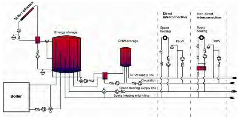
Due to the high distribution losses in the DHW supply and circulation lines, this concept is especially recommended for local heating grids with high energy densities (high heating requirements per length of heat distribution pipe) such as Army New-Recruit Troop Training Sites.
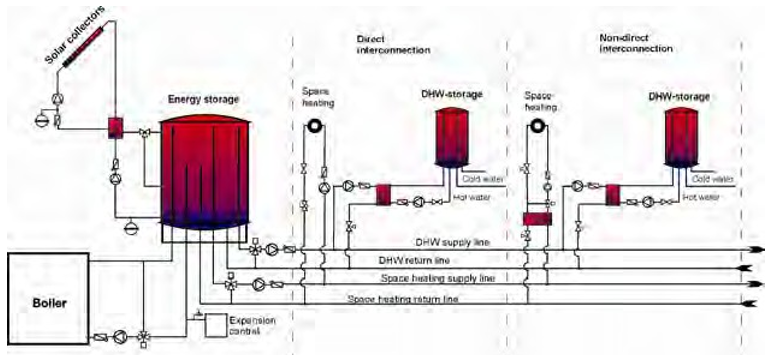
The four-pipe network shown in (Figure 3.25) consists of centralized energy storage and decentralized domestic hot water storages in the buildings.
The energy supply for space heating and domestic hot water is performed by two pairs of distribution pipes using the heating water as the heat transfer medium within the whole heating network.
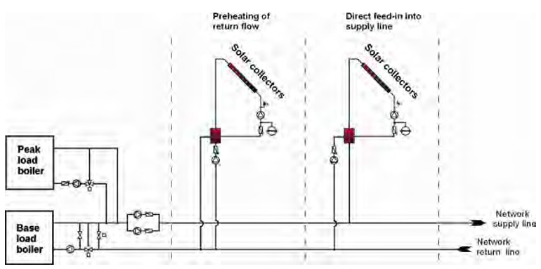
Due to its higher specific investment costs, this concept is especially recommended for local heating grids with high energy densities (high heating requirements per length of heat distribution pipe) such as Army New-Recruit Troop Training Sites.
The direct interconnection of a solar thermal system to an existing district heating network (Figure 3.26) is applied to provide some base load energy directly to the grid. In general, two different applications are most commonly used:
- solar thermal system directly preheating the return line of an existing district heating network
- solar thermal system directly feeding the supply line of an existing district heating
Applications of this kind are commonly designed based on the available space and the existing dimensions of the district heating branch on site, and not on the actual load in a specific building. The solar collectors can either be roof- or ground-mounted. The majority of these systems can be operated without additional storage as they use the district heating network as storage (as long as they provide a small amount of heat in comparison to the total load in the district heating system).
3.5.3 Balancing fluid flow in collector field
A large solar hot water system will flow through many solar collectors. The flow through each solar collector should have basically the same pressure drop. This will ensure that the system is balanced such that each collector is receiving the same flow rate of heat transfer fluid. Thus the fluid temperature increase of each collector will be equal to the others. With several collectors, a reversed return piping system is used to achieve the equal pressure drop. This assumes each collector is arranged to have parallel fluid flow. In some systems, the collectors are arranged for flow in series. Here the fluid goes from one collector to the next collector picking up heat along the way. Figure 3.27 shows the parallel and series flow arrangements. There is a limit to the number of collectors that can be arranged in series due to the pressure drop of the flow through so many collectors.
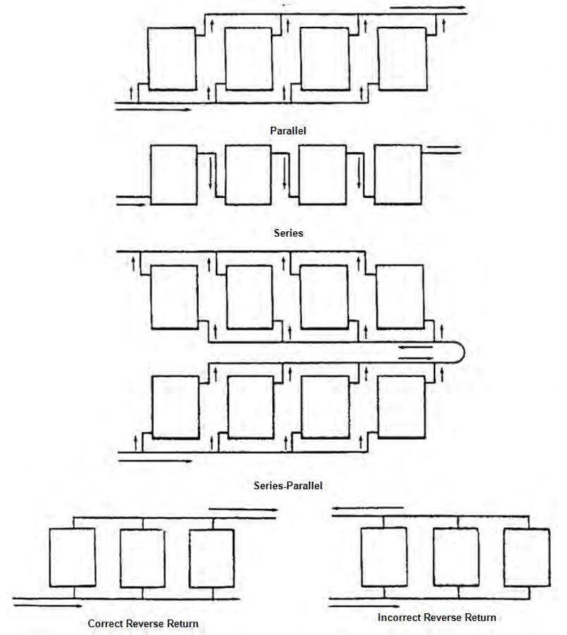
In large collector systems a combination of parallel and series flow is used. An arrangement of collectors that have series flow are placed in a group or zone. Each group is then arranged to have parallel flow with the other collector groups. Figure 3.27 shows such arrangement. The collector layout could also have a group collectors with parallel flow placed in series with another collector group having parallel flow.
The design objective is for the pressure drop of each group to be equal. This is accomplished using a reverse return piping layout (Figure 3.27). The amount of piping should be kept at a minimum to keep installation costs low and to minimize the system resistance to flow, which helps keep the required pump pressures at acceptable levels. A rule of thumb is for the pressure drop per pipe length in the collector to be slightly more than three times the pressure drop per pipe length in the general piping system.
With these large solar thermal systems it is advised to design the collector loop system as a low flow system. That means that the flow rate is ~0.37 gal/sq ft*h (15 l/m2). By contrast, in the so called high flow type the flow rate is in the range of 1.23–1.72 gal/sq ft*hr (50–70 l/m2*hr). This type system is well suited for small (less than 161sq ft [15 m2]) solar DHW systems and for applications having a small temperature rise such as solar cooling applications. It is possible with a low flow system to connect more collectors that are piped for series flow. The flow through an individual collector is then less compared to a high flow operation mode and a higher temperature rise is possible. The benefits of a low flow system are its:
- lower investment costs due to smaller pipe sizes required
- lower piping lengths, as more collectors are connected in series (lower investment) and reduced heat losses
- smaller pump requirements (lower investment), which use less pump energy (lower operation costs) due to lower volume flow
- requirement for less fluid in the solar loop, and consequently less glycol (lower investment)
- quicker response to achieving the target temperature in heat storage tanks including those using stratified charging
- ability to achieve a useful temperature in a single flow cycle a greater percentage of the
Table 3.10 lists the range of specific mass flow rates of the various operating modes of the solar installations and the differences in the total mass flow rate in the feed and return piping of an assumed collector area of 10,760 sq ft (1000 m2). This example shows that larger manifold pipe sizes and higher electric pump power are required when the high-flow operating mode is used in large-scale solar thermal systems. The costs of installing and operating this type of system would therefore soon exceed acceptable limits.
3.5.4 Freeze protection
When water freezes, it expands. Frozen water in pipes is likely to rupture them. This is a major cause of breakdown of solar heating systems. Water thus must be prevented from freezing inside the collector loop. The following options will protect against freezing of the piping system:
- Provide drain-back pipe design.
- Use an antifreeze solution in the outdoor collector and piping, a water-glycol
- Add heat from the storage tank to the outside piping and collector
Each solution has its benefits and drawbacks. Some general aspects are discussed here. The freeze protection implemented is usually not a free choice, but depends on the selected collector technology and supplier; it is usually based on environmental conditions, operating temperature, maintenance, costs, and local availability.

In a drain-back system design the water drains from the collector when the collector pump is stopped. This requires that the collector is constructed and the piping is installed so that no water remains in any part that could freeze. A continuous downward gradient for all the draining pipes is needed to avoid locations where pipes sag and where water can be trapped; this can be difficult to achieve. After a system draindown, the system pump is started to fill the pipes and solar collector with water. This means that the pump must be able to push the circulating fluid up the piping system when starting. The extra amount of pump pressure needed is equal to the height difference between the top of the collector and the position of the drain-back storage vessel. The drain-back approach can also be used during stagnation periods, preventing the formation of steam, and avoiding the resulting expansion and high pressures within the collector. Refer to Section 3.5 for various collector piping arrangements.
Please note: Common practice of solar system designers in Europe is to use a water glycol mixture in drain back systems nevertheless. This way it is ensured that heat transfer fluid does not freeze if draining does not work perfectly. The remaining advantage of drainback systems is: Overheating of oversized collector fields does not necessarily lead to problems during stagnation.
When using a water-glycol mixture the freezing temperature of the mixture is lowered (lower than water alone). The mixing ratio determines the lowest operating temperature. It is important to follow the manufacturer’s or installation engineer’s recommendations. The different types of glycol that could be used vary in their properties. See Section 3.4.1 (p 33) for more information. The pipes still need to be pitched to drains so that the collector field can be emptied for maintenance even when a anti-freeze collector fluid is used.
The main drawbacks of using a glycol antifreeze water mixture are that:
- The heat capacity of the fluid is reduced while the viscosity is increased. This causes a reduction in efficiency of the collector field. In addition, for a comparable mass flow more pump energy is
- Glycol deteriorates when heated up to common collector stagnation temperatures that occur in evacuated tube collectors. Deteriorated glycol forms solid particles that can block and even destroy the collector loop. The glycol mixture then must be
- Care must be taken when an antifreeze solution is used to heat domestic water (which is a potable water source). The two fluids must be kept separate with a leak detection device at the point of heat exchange. This affects the efficiency of the heat
The third option is to use water in a closed, always filled loop, and to heat up the collector loop by turning on the pump when near freezing temperatures are sensed. This means that heat from the storage tank is used to prevent the collector and piping from freezing. This has the obvious drawback of wasting captured heat and using pump power. Therefore, the viability strongly depends on the site with the specific occurring ambient temperatures in winter. It would probably be the logical choice at locations where freezing temperatures are not normally experienced. This option also requires a reliable power supply because if no power is available, this option will fail to protect the collector loop.
3.5.5 Air elimination
When the piping system is filled with the heat transfer fluid air is pushed out of the pipes as the fluid enters. This air must be removed for proper flow to occur. To remove this air, valved openings in the pipe system are installed at high points. These are called “air vents”; their valves are opened to allow air to escape. Usually a 3/8-in. (9.52 mm) ball valve is used. This is a manual operation and when fluid begins to be released at these high points the valve is closed with the captured air is removed. This air removal exercise must be done not only at the initial fluid fill, but also a short time after operation begins and then on a routine basis thereafter. Gases are released from the fluid as it is heated and trapped air can be moving through the system as bubbles. With a fluid velocity greater than 1.3 ft/second (40cm/second), these gas bubbles will move with the fluid until they reach the air vents in the system and there they can be released. The air vents consist of a short section of an expanded pipe section with a valved pipe outlet placed on the top of the expanded pipe section. The larger pipe volume allows the gas to collect without disturbing fluid flow and thus the gases can be removed when the air vent is opened.
3.5.6 Heat loss
The collector loop piping system between collectors and storage tank must be insulated to avoid energy losses. The thickness of insulation on pipes of up to 1 in. (22mm) (outside diameter) should be at least 0.8 in. (20 mm), pipes up to 1-1/2 in. (42mm) should have at least 1.18 in. (30 mm) insulation.* Mineral wool is a widely used insulation of solar system installations. Any pipes and insulation material that are exposed (to weather and animals) should be resistant to damage (e.g., UV degradation and removal by birds) as not to fail. Zinc coated steel, aluminum, or stainless steel are all common materials used for the pipe insulation covering.
3.6 Storage tank
3.6.1 Tank configuration and use
A challenge in applying renewable energies is often the mismatch between the time energy is needed and the time energy is available. Thus storage tanks are a necessary part of any hot water system since they couple the timing of the intermittent solar resource with the timing of the hot water load.
For systems that provide heat for domestic hot water, 1 to 2 gal (3.8–7.5 L) of storage water per square foot of collector area are generally adequate. The storage fluid can either be potable water or non-potable water if a load side heat exchanger is used. For small systems, storage is most often in the form of glass-lined steel tanks. Solar heated water may be stored in a “one-tank” system, or it may be stored in a separate tank that feeds into the tank of a conventional gas or electric water heater (a “two-tank” system). Whether one or two tanks are used, solar energy heats the water before use. On sunny days, a typical solar system can raise water to 140 °F (60 °C).
Bigger commercial solar hot water systems are basically the same as those used for homes, except that the thermal storage tank, heat exchanger, and piping are larger. The storage tanks in these applications are commonly steel tanks with an enameled interior coating. The sizes of these components are proportional to the size of the collector array. Most systems include a backup energy source such as an electric heating element or are connected to a gas or fuel fired central heating system that will heat the water in the tank if it falls below a minimum temperature setting, enabling the system to work year-round in all climates.
If the solar hot water system provides for some of the building heat, a larger storage tank may be advisable. Figure 3.28 shows a breakdown of common storage types.
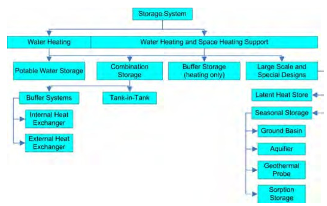
Most large systems have stratified storage tanks where cooler temperatures are at the tank bottom and the hotter temperatures are at the top. The cooler fluid is drawn off the tank bottom and is sent to the collector system for heating. It may go directly to the collector or be used to cool the heat transfer fluid that is then sent to the collectors. Using this cooler water, increases the collector efficiency. The heat transfer fluid is held in the collector until it reaches the desired hot temperature. This is accomplished by stopping the fluid flow or by slowing the flow in the collector until the desired temperature is reached.
Thermal losses from the storage tank are a significant part of the heat balance of the solar thermal system. The losses are proportional to the surface area of the storage tank. Because the volume of a solid body (e.g., cylindrical storage tanks) increases faster than its surface, larger storage tanks have a lower heat loss per volume than smaller tanks. Combining multiple storage tanks into one large storage tank is thus beneficial regarding reducing storage heat losses. All storage tanks need to be insulated to reduce the amount of heat lost from the system. It is good practice to limit the heat losses to 10% of that in the storage tank over 24 hrs. An insulation value of R-16 is the minimum insulation required. If the tank is placed outdoors the insulation should have a weather proof cover.
The storage tank temperature must satisfy the required service temperature and quantity. For DHW, this would be 140 °F (60 °C). For other heating needs the temperature could be hotter. A hotter temperature than the service requirements in the storage tank allows for greater storage of heat, but reduces the collector efficiency. This consideration for the storage tank normally results in a design that provides a stratified water condition in the tank with the hot water on the top and the cold water at the bottom. Stratification of the water is naturally achieved and maintained if mixing of the water is minimized since the cooler water has a higher density and tends to stay at the tank bottom. For good stratification, the tank should be as tall as possible, which means a high, narrow tank is best. Such a tank could be divided into several shorter tanks plumbed in series where the outlet at the top of the first is connected to the inlet near the bottom of the second and later tanks similarly piped. Up to four tanks are often installed in this manner for large systems. If one large tank is used, there may be a pipe connection in the middle section that allows for the entry of water at a temperature warmer than the cold water at the bottom, but not as hot as that in the upper part of the tank. Using this technique minimizes the mixing of the stored water and helps keep the water column stratified.
For larger storage tanks it is common not to store drinking water in the whole storage volume, but to use an internal or external heat exchanger through which drinking water flows for heating (see Figure 3.29). This avoids Legionella growth at mid temperatures, eliminating the need to heat to higher temperatures, more than 140 °F (60 °C).
The most commonly used storage tank systems are used for short-term storage, and are designed to store surplus solar energy for 1–2 days (diurnal storages). This limits the possible solar fraction* (SF) to 10 – 20% of the total heat demand (space heating + DHW) supplied by the solar system, but provides the lowest system investment cost.
Long-term storage tank systems can compensate for seasonal fluctuations in solar irradiation between winter and summer, which can include solar fractions in the range between 40 and 70%. The negative effects are higher system investment costs and higher heat losses of the system. Between short and long-term storages, weekly or medium-term storages have been realized in Austria.
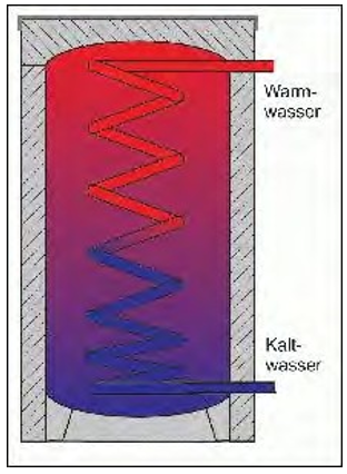
heating domestic hot water.
3.6.2 Legionella considerations
One should exercise caution to avoid the risk of the growth of the Legionella Pneumophila bacterium. These bacteria are naturally found in water, but at low concentrations. They can multiply quickly when the water temperature is between 86 and 113 °F (30 and 45 °C).† Their numbers start to diminish at temperatures above 122 °F (50 °C), and almost instantly die above 150 °F (66 °C). The greatest health danger is not in drinking contaminated water, but in inhaling contaminated dispersed water droplets, which can happen when taking a shower. Storing large quantities of water at temperatures in the range of 86 to 113 °F (30 to 45 °C)should be avoided when it is intended to be used (from a tap) later. Local legal requirements may apply to this issue and should be taken into account.

The typical approach in the United States to avoiding the Legionella bacteria issues is to store the hot water at 140 °F (60 °C). Other design options are to limit the quantity of usable hot water by means of a heat exchanger or tank-in-tank construction, where the temperature of the delivered water is 140 °F (60 °C). In Europe, other options include periodically reheating the water above 150 °F (66 °C) (setting the controller for the auxiliary heater to do this when solar heat alone cannot achieve this), or instantly heating the water just before use to above 185 °F (85 °C).
3.7 Heat exchangers
In the solar hot water system heat exchangers transfer the heat from one moving fluid to another. To achieve the temperature transfer the fluid from the collector will be hotter than the leaving temperature of the secondary fluid. This higher temperature from the collector has a negative effect on system performance. To keep this temperature difference as small as possible a plate-and- frame heat exchanger is used. Where this temperature difference is not a large concern a shell- and-tube heat exchanger can be used.
When the solar thermal system is used to heat domestic water there must be a guarantee that the heat transfer fluid is kept isolated from the potable water source. This is normally accomplished by separating the two fluids by a vented open space, or by using a third fluid that could be monitored for fluid leakage. The double wall or additional heat exchanger also protects the solar collector fluid from being diluted by water and becoming prone to freezing. (Refer to Section 5.3.5 [p 80]).
All heat exchangers have a small pressure drop of the fluid passing through them. This must be considered in selecting the pumps. Their materials of construction need to be compatible with the heat transfer fluids and with other materials in the piping system. They also need to be able to withstand the temperatures and pressures that will be experienced in the system. To achieve good heat transfer and to adhere to the other requirements, stainless steel and copper are the normal materials used in these heat exchangers.
The pipe design at the heat exchanger that transfers energy from the collector to the storage tank may need a by-pass pipe circuit around the heat exchanger for the collector heat transfer fluid if an antifreeze solution is used. The antifreeze solution on cold days during system startup could be several degrees below freezing and thus could freeze the water in the heat exchanger from the storage tank when flow begins. The pipe bypass would be opened when the collector pump is started. The valves would be closed to allow flow through the heat exchanger when there is usable heat in the heat transfer fluid (a temperature ~80 °F [27 °C]). This action will also avoid cooling the heat exchanger during the initial flow of the collector heat transfer fluid that was downstream of the solar collectors.
A comparison between the two types of heat exchangers will show the following results. Plate-and- frame heat exchangers have small passageways and thus have a higher pressure drop and are more prone to flow blockage due to contaminants in the circulating fluids. They have a quicker reaction time and typically take less space in the piping system. A shell-and-tube heat exchanger can handle fluids having more contamination. These heat exchangers are easier to clean and have a lower pressure drop for the fluids flowing through them.
Selection of the size of the heat exchanger depends on the amount of heat that must be transferred and the desired leaving temperature. An increased heat transfer surface area is needed for improved performance. Note that heat exchanger ratings are established using water as the heat transfer fluids. With the use of an anti-freeze fluid, heat exchange performance will decrease and the exchanger surface area will need to increase. A water-glycol mixture has a higher viscosity and lower heat capacity. Heat exchanger manufactures can provide useful information to aid selection.
3.8 Pumps
Pumps move the heat transfer fluids through their piping circuits. The pump associated with the collector fluid will be exposed to the highest temperature and the greatest pressure. To minimize the high temperature in this loop, the pump is placed in the pipe going to the collectors. But even here there will be short term periods when the pump is handling temperatures greater than the design collector discharge temperature. Such a time is when the hot heat transfer fluid has been forced out of the collector into the recapture tank due to stagnation. If using an anti-freeze solution as the collector heat transfer fluid, the pump components will need to be compatible with the water/glycol mixture. These considerations will affect the materials used in the construction of the pump.
The pump will also need to operate through the flow range that is designed for the system. In some solar thermal systems, the heat transfer fluid flow is slowed when the solar radiation is not at its peak. At this lower flow the pump must still provide the required pressure to obtain fluid movement through the pipe system. Having clean fluid strainers/filters, a minimum of valves, and properly operating sensors will aid in keeping the system pressure drop as low as possible. In large systems, the piping system flow is modeled to define the pump pressure needed for proper operation. It is important to take into account that glycol/water mixtures have a different viscosity than water alone. The manufacturer of the heat transfer medium should provide the necessary data. The energy needed to pump the heat transfer fluid is considered parasitic energy; it must be kept as low as possible. The pump should thus not be oversized.
3.9 Expansion tank
As the heat transfer fluid increases in temperature its volume also increases thus an expansion tank is used to capture the addition fluid as it is pushed out of the piping loop. The expansion tank also helps prevent the loss of heat transfer fluid that would escape the piping system through the safety valves during high temperature periods. When the heat transfer cools, fluid in the expansion tank can then flow back into the system.
Most expansion tanks are a steel tank with a rubber membrane inside. On one side of the membrane is a gas such as nitrogen, which is under a pressure equal to the system operating pressure. On the other side of the membrane is the space where the extra heat transfer fluid goes when expansion of the fluid occurs. The membrane material will begin to deteriorate when exposed to temperatures above 160 °F (71 °C). To protect the expansion tank from such high temperatures, they should be connected to the piping that goes to the collector. This will be where the coolest fluid will be found. If temperatures exceeding 160 °F (71 °C) are expected in this pipe then a buffer tank or auxiliary reserve tank should be placed between piping loop and the expansion tank. This is a normal steel tank filled with heat transfer fluid. Since it is not circulating in the collector piping system loop, it will be somewhat cooler. When expansion occurs, the extra hot fluid will enter the auxiliary reserve tank causing the residing cooler fluid then to enter the expansion tank protecting its membrane.
The membrane expansion vessel may need to be designed to compensate not only the additional volume of heated up fluid, but also the volume of steam that is produced by the collector field. That can be more than just the volume of the collectors. Water in pipes above the collector field, for example, can drain into the collectors after they are already empty and then start to produce even more steam.
3.10 Back-up/supplemental heater
Each solar thermal system must have a back-up heating supply. Often gas or electricity and sometimes biomass (wood) are used as a heat source. Due to the 20+ year lifecycle of heating systems, including solar thermal systems, possible changes in energy supply options should also be considered.
It is important to control the solar energy system to provide the required temperature to the building energy systems. So if the domestic hot water must be 140 °F (60 °C), the heat transfer fluid must be hot enough to deliver that temperature. If it is not, then the supplemental heating system will be energized causing additional energy costs to occur. Running the supplemental heater is often very inefficient for this use since it would be cycling on/off and would not be operating at its normal firing rate.
3.11 Controls
The controller controls the flow of the heat transfer fluid in the collectors by modifying the pump operation. Normally the pump is just turned on/off in small systems. The most common pump controller used in solar thermal systems is the “differential controller.” This controller requires two different temperature settings, one for “on” (upper band) and one for “off” (lower band). The system temperatures are measured on an absorber in a collector (usually one whose flow is a short distance to the storage tank) and in the storage tank (near the tank outlet to the collectors) or in this discharge pipe adjacent to the tank. If the collector temperature exceeds the storage tank temperature plus the upper band the pump will turn on. If the collector temperature drops below the store temperature plus the lower band the pump will turn off. A common upper band (“on”) temperature difference is 41–46 °F (5–8°C) and for the lower band (“off”) 36–39 °F (2–4 °C). Proper location of these sensors is very important. Good placement guarantees that the pump only runs when this is beneficial for collecting solar energy that can be stored in the tank. Failing to measure the temperature difference correctly will affect the overall system performance significantly; this requires care and verification at the installation.
The controller also must turn off the pump when the maximum storage temperature (e.g., 194 °F (90 °C) is reached, or when the collector exceeds the maximum flow temperature (e.g., 68.00 °F [20 °C]).
Some pump-controller combinations offer different power settings (often step-wise) to be able to match the mass flow rate with the amount of solar radiation available. This limits the temperature increase in the solar circuit and prevents unnecessary pumping.
More advanced controllers offer additional functionality: insolation and heat measurement, data- logging, error diagnostics, and auxiliary heater (boiler) regulation, and a graphical user interface.
Chapter: 4 DOD Installation Solar Hot Water Applications
4.1 Areas of potential Army use
There are a number of Army installations in the United States. They break down into several general types: Introductory troop training, General troop installations, Proving Grounds, Depots, and Arsenals. The installations that emphasize the training and support of troops have a large number of housing units and corresponding dining facilities. Both of these types of buildings have a high domestic hot water use and are good candidates for solar hot systems. All Army installations have recreational and health care facilities, which also could be large domestic hot water users. The administration, maintenance, training, storage, manufacturing, and service facilities are typically low domestic hot water users and thus are poor candidates for a central solar hot water system to heat their domestic water.
Air-conditioning system reheat for humidity control is another year-round heating energy use and thus is a candidate for a solar hot water system. Humidity control is required in some administration, data processing, communication, and health care buildings. To accomplish this control, the air in the air-conditioning system is chilled to a low temperature for moisture removal. This air is normally too cold to introduce into occupied spaces so it is reheated to a more comfortable temperature. The energy to accomplish this reheat is a good candidate for the heat provided by a solar hot water system.
Building profiles found at the different types of Army installations are:
- Army Introductory Troop Training Sites (Fort Benning, Fort Jackson, and Fort Sill)
- High density barracks and lodging
- Dining facilities
- Administration buildings
- Company Operation Facility (COF)
- Maintenance facilities (motor pools, aircraft wash areas, car washes)
- Recreational (Fitness centers, pools)
- Training
- Healthcare
- Service (Fire and police stations, PX, AAFES)
- Storage
- Central heating plants
- Army Troop Locations (Fort Bragg, Fort Campbell, )
- Barracks and lodging
- Dining facilities
- Administration buildings
- Company Operation Facility (COF)
- Maintenance facilities (motor pools, aircraft wash areas, car washes)
- Recreational (fitness centers, pools)
- Training
- Healthcare
- Service (fire and police stations, PX, AAFES)
- Storage
- Army Proving Grounds
- Research and manufacturing buildings
- Lodging
- Storage facilities
- Administration buildings
- Recreational (fitness centers, pools)
- Healthcare
- Maintenance facilities (motor pools, aircraft wash areas, car washes)
- Service (fire and police stations, PX, AAFES)
- Army Depots
- Research and manufacturing buildings
- Lodging
- Storage facilities
- Administration buildings
- Recreational (fitness centers, pools)
- Maintenance facilities (motor pools, aircraft wash areas, car washes)
- Service (fire and police stations, PX, AAFES)
- Army Arsenals and Ammunition Plants
- Manufacturing buildings
- Lodging
- Storage facilities
- Administration buildings
- Recreational (fitness centers, pools)
- Maintenance facilities (motor pools, aircraft wash areas, car washes)
- Healthcare
- Service (fire and police stations, PX, AAFES).
The size of these installations can be small with as few as 50 occupied buildings. Others are very large, having a population more than 70,000 people. Some are in very cold climates and others in extremely hot/humid climates. A better description of each can be obtained by doing a internet web search on a specific installation.
There is no “average size” Army installation; they have grown over time to serve a number of different needs. Perhaps the best way to approach Army building groups is to look at what the Army is doing now. The Army has recently standardized on a grouping of buildings to support the supervising, housing, and training of combat troops. The troops are organized into a Brigade size fighting unit and thus is called a Brigade Combat Team (BCT). The group of buildings are arranged in a manner shown in Figure 4.1. Looking at this layout, the BCT consist of Barracks (light blue) with a Dining Facility (purple) in the middle. Then the Headquarter Building (orange) is close by on a through street. South of this street are green buildings called Company Operation Facilities (COF) and red buildings called Tactical Equipment Maintenance Facilities (TEMF). The total building floor space is about 1,402,000 sq ft (130,386 m2), which is divided into Barracks with 567,000 sq ft (52,731 m2), Dining Facility with 31,000 sq ft (2,883 m2), Tactical Equipment Maintenance with 229,000 sq ft (21,297 m2), Company Operation Facilities with 447,000 sq ft (41,571 m2), and 129,000 sq ft (11,997 m2) for the Headquarters building.
The buildings that have the major DHW heating requirements are the barracks and the dining facility. Some healthcare and recreational facilities also have a high DHW heating need. The rest of the buildings have a very small DHW heating requirement that is most often satisfied with small local heaters. As can be seen below there are 11 barracks buildings and one dining facility in the BCT cluster. The average barracks size is 51,500 sq ft (4790 m2). Each barracks will house ~260 soldiers. The dining facility is 31,000 sq ft (2880 m2).
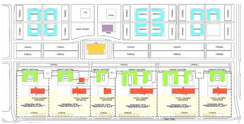
The heating of these buildings can be from a central source such as a boiler plant that serves the entire installation or a group of buildings within the installation. Another method often seen is individual boilers in each building with one for heating the building and the other for generating DHW. Even with a central boiler system heating the DHW is often by local building boiler equipment.
Few Army installations have a cogeneration system where both electricity and heating hot water are generated in the central plant. Most Army central boiler plants provide heating only and thus it can be desirable to turn this system off during the nonheating season. About half the central systems are steam distributed at a pressure in the range of 60 to 100 psi (414 to 689 kPa). The others are hot water with temperatures as hot as 400 °F (204 °C).
The most common system is the use of local heating systems within a building. In this case DHW is generated using a hot water boiler. The next most likely situation is a central heating system that is used to heat the buildings, but the DHW is generated by a hot water boiler as above.
4.2 Building hot water demands
The barracks and dining facilities are large DHW users. The estimated DHW needs for a barracks building is 30 gal (114 L) of hot water per soldier per day at a temperature of 140 °F (60 °C). Most soldiers take two showers per day and one of them is in the morning, from 7:30 am to 8:00 am. To handle this peak usage DHW is stored in a tank having the size of ~22.5 gal (85 L) per soldier.
Figure 4.2 graphs the heating rate throughout a typical week for a person’s DHW use in a barracks. Such a high DHW heating energy use makes a barracks a good candidate for a central solar hot water system.
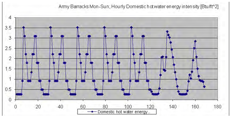
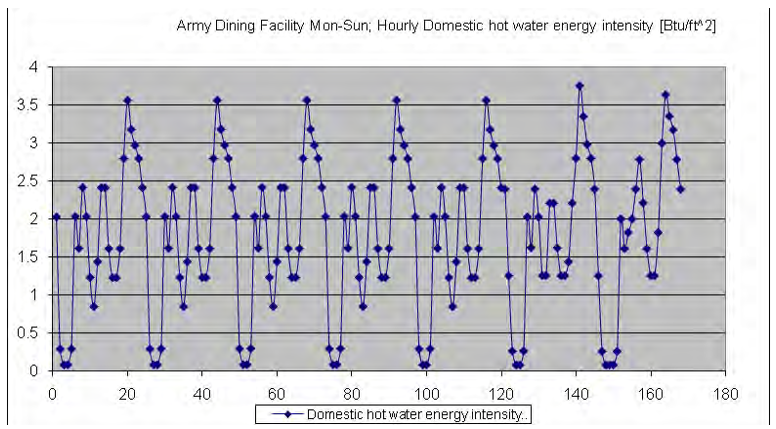
The other building in the cluster that should be included in the central solar hot water system is the dining facility. Figure 4.3 graphs DHW heating energy needs. Typically, these facilities are occupied from 5:30 am to 7:30 pm. Three meals are served per day – breakfast (7:30 to 9:00 am), lunch (11:00 am to 1:00 pm) and supper (5:00 pm to 6:30 pm). The schedule will change slightly on the weekend. The hot water use of this facility is ~2.4 gal (9 L) per meal served. Assume that a dining facility of this size would serve 7500 meals each day.
The office buildings have a hot water use of ~1 gal (3.79 L) per person per day. If the occupancy of the building is not known, use 100 sq ft (9.3 m2) per person.
Another source for domestic hot water use is provided by NREL (shown below). Some guideline for determining hot water loads for sizing commercial SHW systems are:
- Apartments: 20 gal (76 L) /day of 120 °F (49 °C) set temperature water per bedroom
- Hotels/Motels: 15 gal (57 L)/day of 125 °F (51.67 °C) set temperature water per room
- Laundries: 20 gal/10 lb (76 L/4.5kg). wash of 130 °F (54 °C) set temperature water
- Restaurants: 24 gal (91 L)/day of 140 °F (60 °C) set temperature water per 10 full meals served
- Retirement Homes: 18 gal (68 L)/day of 120 °F (49 °C) set temperature per room
- Office Buildings (without showers): 1 gal (3.79 L)/day of 120 °F (49 °C) set temperature water per
4.3 Basic solar system design
Selecting the right solar water heating system for a federal facility will depend on three key factors: climate, budget, and water usage needs. Solar water heating systems are economical, especially in commercial buildings where the energy used to heat water is significant. There are a number of technologies available to heat water efficiently. However, before implementing these technologies, it is important to first reduce hot water use with water-saving fixtures and appliances.
Solar water heating systems can be used throughout the United States on any building with a south-facing roof or unshaded grounds for installation of a collector. In addition, reliable off-the-shelf systems can be selected from the Directory of the Solar Rating and Certification Corporation at: www.solar-rating.org/ratings/ratings.htm
The Arizona Solar Center Albuquerque, NM uses system sizing estimates based on climate:
- Sunbelt—use 1sq ft (0.09m2) of collector per 2 gal (7.61 L) of tank capacity (daily usage).
- Southeast and Mountain states—use 1 sq ft (0.09 m2) of collector per 1.5 gal (5.71 L) of tank capacity.
- Midwest and Atlantic states—use 1 sq ft (0.09 m2) of collector per 1.0 gal (3.79 L) of tank capacity.
- New England and the Northwest—use 1 sq ft (0.09 m2) of collector per 0.75 gal (2.81 L) of tank capacity.
Estimates will be affected by water temperature, consumption amount, and the solar resource available at the site.
4.3.1 Simple system calculation
A simple evaluation procedure can help to determine if solar water heating is appropriate. Traditional solar hot water heating systems are most cost effective in facilities with:
- Constant water heating load throughout the week and year; housing units and dining facilities are good
- High fuel costs to heat water; this is area
- Sunny climates (which helps, but is not required); this is area
The economic viability of a solar system depends on:
- amount of annual sunshine
- heating energy requirements throughout the year
- cost of the solar system
- price of conventional fuels (are the utility rates high in your area?)
- financing and incentives available (for 3rd party investors)
- what temperature of hot water is required (e.g., swimming pool vs. laundry)
- annual operation and maintenance
The step-by-step method listed in Table 4.1 can be used to estimate the solar system size and its cost effectiveness. Table 4.2 lists general data for water heating loads for building types, solar resource, etc. Numbers are included for a sample building in Denver, CO and assume that the building uses electricity to heat water. The sample building group is four barracks, each housing 120 soldiers for a total of 480 soldiers. With a hot water use rate of 30 gal (114 L)/day/person, the hot water use would be 14,400 gal (54,000 L)/day. The heating energy to make this hot water is:
Q = 14,400 gal/day x (140 °F – 60 °F) x 1 Btu/lb/°F x 8.3 lb/gal /3413 Btu/kWh = 2800 kWh)/day = 9,556 MBtu/day
4.3.2 Equation 1 – Solar water system size

The paper “Annual System Efficiencies for Solar Water Heating” by Craig Christensen of National Renewable Energy Laboratory and Greg Barker of Mountain Energy Partners presents calculated efficiency for domestic solar water heaters that varies between 26.4% and 44.3% depending on location and hot water load with an average of 40.2% for all locations and load profiles.
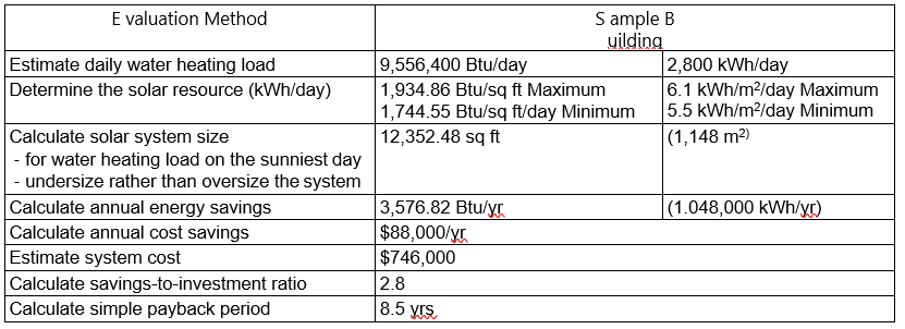
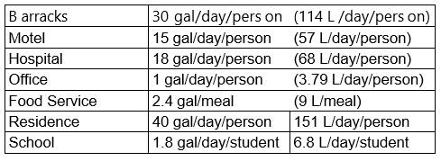
4.3.3 Equation 2 – Annual energy savings

4.3.4 Equation 3 – Annual cost savings

4.3.5 Equation 4 – Solar system cost

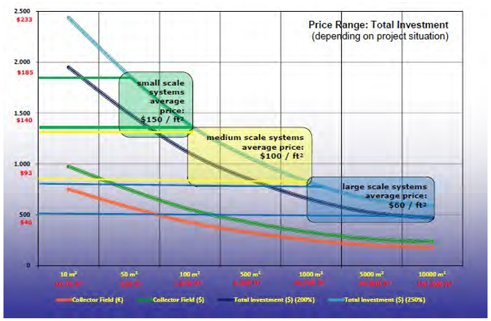
4.3.6 Equation 5 – Savings -to-investment ratio

4.3.7 Equation 6 – Simple payback period
![]()
Another system sizing analysis would be:
For a location receiving 2,220 – 2,854 Btu/sq ft (7–9 kWh/m2) on a high-radiation day a system that will provide heat for a domestic hot water system located will have a degree of utilization of ~50%. The result is 1,110 to 1,427 Btu/sq ft (3.5 to 4.5 kWh/m2) of collector area provided as useful heat for generating the hot water. The value of 4.0 kWh/m2 is equal to 13,650 Btu/m2 or 1,270 Btu/sq ft of collector. This amount of heat can raise 19.2 gal water/m2 from 55 to 140 °F. A sq ft of collector area can heat 1.8 gal. A solar storage system for this application should be in the range of 60 to 70% of the normal daily use. If the daily use is 1.8 gal/sq ft, then the storage tank size would be ~1.2 gal per sq ft
4.3.8 More accurate sizing approaches
Consider a typical solar system providing heat to maintain domestic hot water at 140 °F (60 °C) in the domestic hot water storage tank. There is an heat exchanger between the solar system storage tank and domestic hot water system. To achieve a DHW temperature of 140 °F (60 °C), the incoming stored water temperature must be 5 °F (2.7 °C) warmer or 145 °F (63 °C) as it enters the heat exchanger, assuming a plate-and-frame type. The design temperature in the storage could be as warm as 15 °F (-9 °C) to provide a few degrees for temperature loss and extra storage capacity. There is another heat exchanger between the water storage system circulation and the collector fluid circulation, which means the collector fluid should be a hot as 160 °F (71 °C) entering the plate-and-frame heat exchanger.
Thus the solar collector leaving temperature will be a minimum 160 °F (71 °C), which will establish the collector efficiency and the amount of heating energy the collector will produce per sq ft area. Knowing the domestic hot water demands and the incoming cold water temperature this will establish the energy demands for heating the domestic water. The size of the solar collector can be determined from this information. In sizing the collector system, an important consideration in the design is the selection of peak solar radiation. As the peak value chosen is reduced closer to an average solar radiation value for a specific installation, there will be periods when the collector will generate heat that the DHC system cannot consume. At these times, the collector system will have no place to send the heat. The flow through the collector will stop and the collector system will go into stagnation with the temperature of the heat transfer fluid going above the design 160 °F (71 °C). If it goes high enough the heat transfer fluid will begin to vaporize.
In Section 4.3.1 (p 57) “rules of thumb” were used to determine the solar collector size. A more accurate evaluation for determining the size of a solar hot water system would use values specific to the collectors that are planned to be used in the system. The Solar Rating and Certification Corporation (SRCC) provides such Information and efficiency ratings for collectors available in the United States. This independent organization tests and provides a certification rating of various solar collectors and solar water heating systems. Equipment that has certified and rated by SRCC must show their certification label that provides the products performance rating. Information from the SRCC is available through URL: www.solar-rating.org/ratings/ratings.htm
The SRCC performance ratings in Btu/sq ft/day are provided under three different solar weather conditions – clear, mildly cloudy, and cloudy skies. Table 4.3 lists the five levels of service. The ratings also include durability and efficiency. This information can be used to compare different types of collectors. Although these ratings give the heat output for collectors, they do not provide cost information. Look at the amount of heat (BTUs) the collector delivers per day relative to its cost.
To compare two panels, first look at the service category (A through E) that represents water use. Then look at the output of the three solar weather conditions for each panel. To determine the collectors that produce the most heat for the least cost, figure the price per square foot of the panels by dividing the panel price by the panel area. When comparing panels, some may perform better in sunny conditions and some will perform better under cloudy conditions. Unless the system will be located in an area with lots of cloudy days such as the Pacific Northwest, it is more important for a collector to do better under sunny conditions than under cloudy conditions because there is more heat to capture on sunny and partly sunny days than on cloudy days.

SRCC also tests and provides performance ratings for small hot water systems. Information is provided on the storage tanks size and the total system performance for locations that can be selected from a pull-down list. The computer program TRNSYS is used to determine the values, which provide the Solar Energy factor (SEF), equivalent Solar Fraction, and equivalent solar savings (QSOLAR).
The performance of a solar hot water system (its “ability to capture solar radiation” and its “ability to deliver hot water”) depends on the configuration of the system (collector area, controller setting, storage volume etc.), the current state of the system (i.e., temperature of the hot water in the storage tank) and factors from its environment (notably the ambient temperature and insolation patterns over the year). Indicators (SF, SN, and SE) that are used to measure the performance of solar thermal systems are discussed in Section 3.1 (p 13). Another indicator is the standby hot water volume, which is the amount of water at the desired delivery temperature that the system can deliver at any time without any instant additional heating required for this delivery. With the following situation, the standby hot water volume is 83 (= 50x[65-15]/[45-15]) liters of water (22 gal) without any additional instant heating.
- Standby storage tank: 26 gal (100 L)
- Backup fraction: 13 gal (50 L)
- Set temperature of the backup: 149 °F (65 °C)
- Tapping temperature: 113 °F (45 °C)
- Cold water feed: 59 °F (15 °C).
The performance parameters SF, SN and standby hot water volume, together with the costs for the heat form a triangle; that by maximizing one, others may be affected negatively. For example:
- Maximizing for SF means that the collector area and the store volume accordingly will be maximized as to make more solar energy available, reducing SN, increasing the costs.
- Maximizing for SN means that the collector area will be undersized, because then excess available energy is avoided, but less solar energy will be available for the user reducing.
- Maximizing for standby hot water volume means that a larger fraction of the store will be at a higher temperature, which requires more auxiliary heating (lower SF) and also has a negative effect on the efficiency of the collectors.
Optimization thus involves a prioritizing and compromising (Figure 4.5).
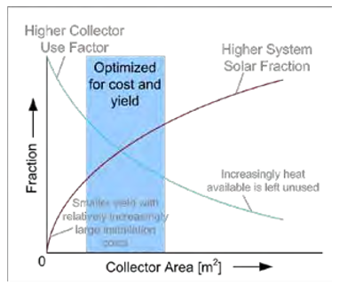
Independent evaluation of single components of a solar system provides limited predictability of the performance of the system as a whole (i.e., yield). With larger components (in particular the collector area and the storage tank) the “principle of diminishing returns” applies. This means that although the yield will increase when the collector area or storage tank volume is increased, the marginal increase becomes smaller with increasing area and volume. In addition, maximizing one component over others also has a strongly diminishing effect. A diminishing effect usually also means an increase in energy costs (increase of marginal and average $/kWh). Simulations with various component sizes aid in the design of an (cost) optimal system.
There are design tools available for sizing the solar collector system. The National Renewable Energy Laboratory (NREL) developed the Federal Renewable Energy Screening Assistant (FRESA) software that can help facility managers determine if their building is a possible candidate for a solar water heating system. This Windows- based software tool screens federal renewable energy projects for economic feasibility and evaluates renewable technologies including solar water heating systems, photovoltaic, and wind energy systems.
A somewhat more detailed screening tool is provided by the Canadian Retscreen. This computer program is available as a free download and it will model glazed, unglazed and evaporative cooling solar hot water collectors. It uses f-chart to calculate the estimated collector area required, annual solar energy yield, solar system efficiency, solar fraction and pumping energy needed. The analysis is based on the input of average monthly solar radiation, outdoor temperature and relative humidity and wind speed. The building’s hot water use is input for an average day over the year. This use cannot be varied. The results of this simulation compares favorably with other year-long evaluations. If a more detailed engineering and economic analysis is required, consider using the following software programs
- F-CHART, correlation method, available from the University of Wisconsin.
- TRNSYS, software, available from the University of Wisconsin.
F-Chart is available for the purchase price of $400 for a single user. It has the capability of modeling flat plate, evacuated tubes, CPC and 1 or 2 axis tracking collectors. It can handle water storage heating, building storage heating, domestic water heating, and integral collector storage heating.
The output can provide a life cycle analysis with cash flow.
Other computer programs that can be used for sizing the solar system are T*SOL and Velasoris Poly Sun. The Federal Energy Management Program (FEMP) Help Line (800-DOE-EREC) provides manuals and software for detailed economic evaluation and for the Energy Savings Performance Contracting Program, which allows federal facilities to repay contractors for solar water heating systems through bills for energy savings instead of paying for initial construction.
4.4 Cost effectiveness
4.4.1 Cost of centralized versus de-centralized systems
Cost of Collectors Vs System Cost. When comparing solar thermal system alternatives: system size, configuration, types of collectors, etc., all cost components over the full lifecycle of the system should to be taken into account. This requires detailed information on the system hardware and results of system’s performance simulation.
Advanced technology and production economies of scale have led to significant cost reductions in solar hot water collectors. The value of shipped low-temperature collectors was $1.89/sq ft (~14 €/m2) in 2008. The average cost of thermosyphon systems with the storage integral to the collector was $24.27/sq ft (~183 €/m2) ; the price of flat-plate collectors was $17.40/sq ft (~131 €/m2); the price of evacuated tube solar collectors was $25.69/sq ft (~194 €/m2); and the price of parabolic trough solar collectors was $11.96/sq ft (90 €/m2) These values are based on collector factory revenue divided by output, so retail prices would roughly double (not including labor for installation), and the installed system price with all the other components is on the order of $75 to $225/sq ft (565 to 1696 €/m2) depending on project size and location. New construction systems usually have better economics than retrofit projects because of reduced installation expenses.
Independent evaluation of a single system component cost and its performance, e.g., solar collector, provides limited information for the whole system evaluation. Increasing the size of a single component (e.g., the collector area or the storage tank volume) results in “diminishing returns.” This means that, although the yield will increase when the collector area or storage tank volume is increased, the marginal increase becomes smaller with increasing area and volume.
Also, maximizing one component over others has a strongly diminishing effect, which usually results in increased energy costs ($/kWh). Simulation of the system with variation of component sizes aid the design and energy cost optimization. Figure 4.6 shows approximate composition of the large system first cost.
Large central solar water heating systems are normally more cost effective due to economies of scale in installation, operation and maintenance compared to several small systems. This includes higher efficiencies possible* for backup heating systems in centralized systems. Table 4.4 lists the approximate effect of the solar thermal system size on investment cost generated from analysis of case studies described in Section 4.5 (p 71).
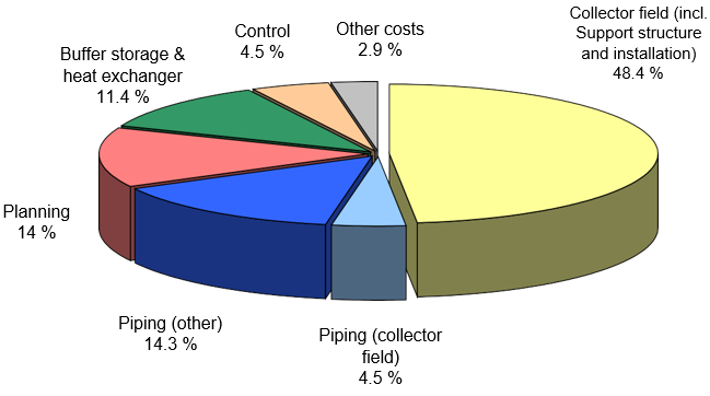

The values in Table 4.4 represent a first approximation and do not apply to every large building or cluster of buildings. The main criterion is the heat demand of the building or a cluster of buildings and their density (required distribution system).
4.4.1.1 System efficiency factor
Losses in heat distribution increase with distance and have an additional negative effect on overall system efficiency. For example, for large centralized systems the required storage temperature and delivery temperatures increase (above the operating temperature) due to heat losses through the walls of a storage tank and in the distribution system. Simulations of specific system is required to determine the overall performance (e.g., distribution losses as a fraction of the energy supplied).
4.4.1.2 Operation
In the particular situations with high peak loads and long periods when there is no hot water use in some buildings (e.g., in barracks during soldiers’ deployment) central system will simplify adjustments needed to control such situations and potentially reduce the damage to the system. In the case of compounds with multiple barracks, large central SWH system can be more easily installed, maintained, and operated. Even finding a location for the solar collectors may be simpler. Large SWH systems also have the advantage in that the influence of individual users is minimal on their operation.
Small SWH systems require periodic checking and maintenance. Scheduling of maintenance for many distributed systems may be an issue of prioritization. On the other hand, maintenance of large central systems is more critical since a larger number of users could be affected and thus system monitoring and preventative maintenance are required activities to assure good performance.
4.4.1.3 Storage
Thermal losses from the storage tank have a significant effect on the efficiency of the solar thermal system. Heat is lost via the surface. The capacity of a sensible storage tank (e.g., water steel tanks) is defined by its volume. The volume grows with the 3rd potency of its circumference. The surface grows with the 2nd potency. Thus storage tank losses are reduced when one large store is used in comparison with many small storage tanks.
4.4.1.4 Back-up /auxiliary heating
Each solar thermal system must have a back-up heating supply. Oil, gas, electricity, or biomass is used as a heat source. Due to the 20+ year lifecycle of heating systems, including solar thermal systems, possible changes in energy supply options should also be considered. This could, for example, relate to future auxiliary (back-up) heating options from biomass (bio-waste) and waste heat supplies. In the case centralized systems, these options are often more easily integrated later.
4.4.2 Large scale SWH cost effectiveness
Monetary savings from installing a solar water heater depends on a variety of factors, including climate, the amount of hot water used at your location, the cost of conventional fuels, and system performance. Using these parameters for a large solar hot water system that could be applied to a cluster of buildings, the cost effectiveness can be illustrated with regional coloring presented on the maps of the United States shown in Figures 4.7 to 4.10. The information presented in these figures are for solar hot water systems that are replacing electrical or gas heating of hot water. An average efficiency of 40% for the solar system is assumed and a life of 40 yrs is used in the analysis. Two solar system costs are used: $50 per sq ft of collector, and $75 per sq ft (~377 €/m2 and 565 €/m2).
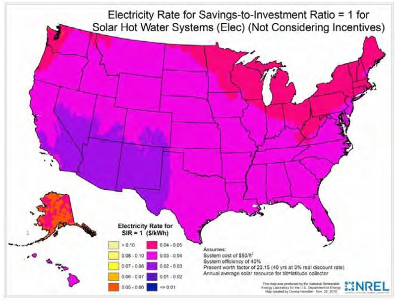
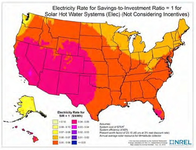
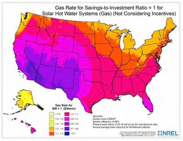
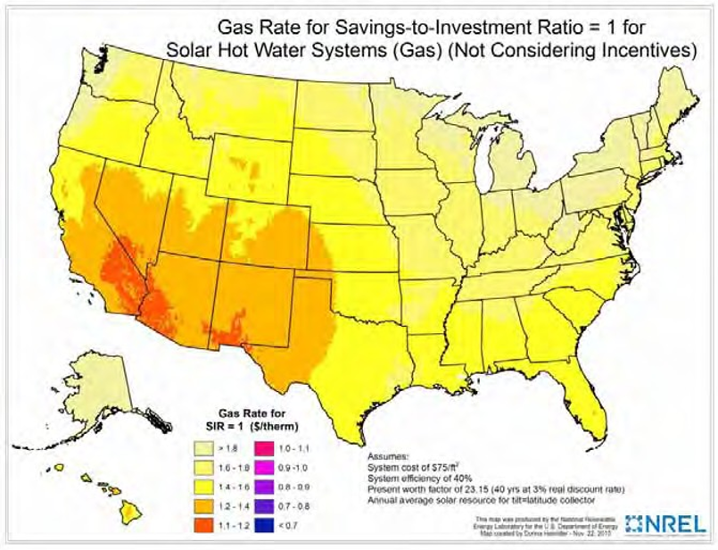
This course is focused on large centralized solar thermal systems with short and medium-term storages connected to heating networks and they provide much lower specific system costs than decentralized small-scale solar systems. As can be seen in Figure 4.11, the cost/benefit-ratio (investment cost/ energy savings per year) for large solar systems with collector areas > 1,076 sq ft (100 m2) is about half that of small, decentralized systems, and can even be reduced by more than 20% when using large scale systems combined with seasonal storages.
A general rule of thumb for federal facilities is that a renewable energy installation should pay for itself within about 10–15 yrs. System life spans can be as much as 30 yrs, which means a facility can look forward to as much as 20 yrs of “free energy.”
There are very few large solar collector systems in the United States. In Europe the use of such systems is more commonplace. Table 4.5 lists the selected systems size, cost, and performance values.
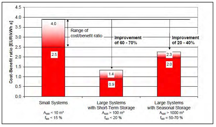

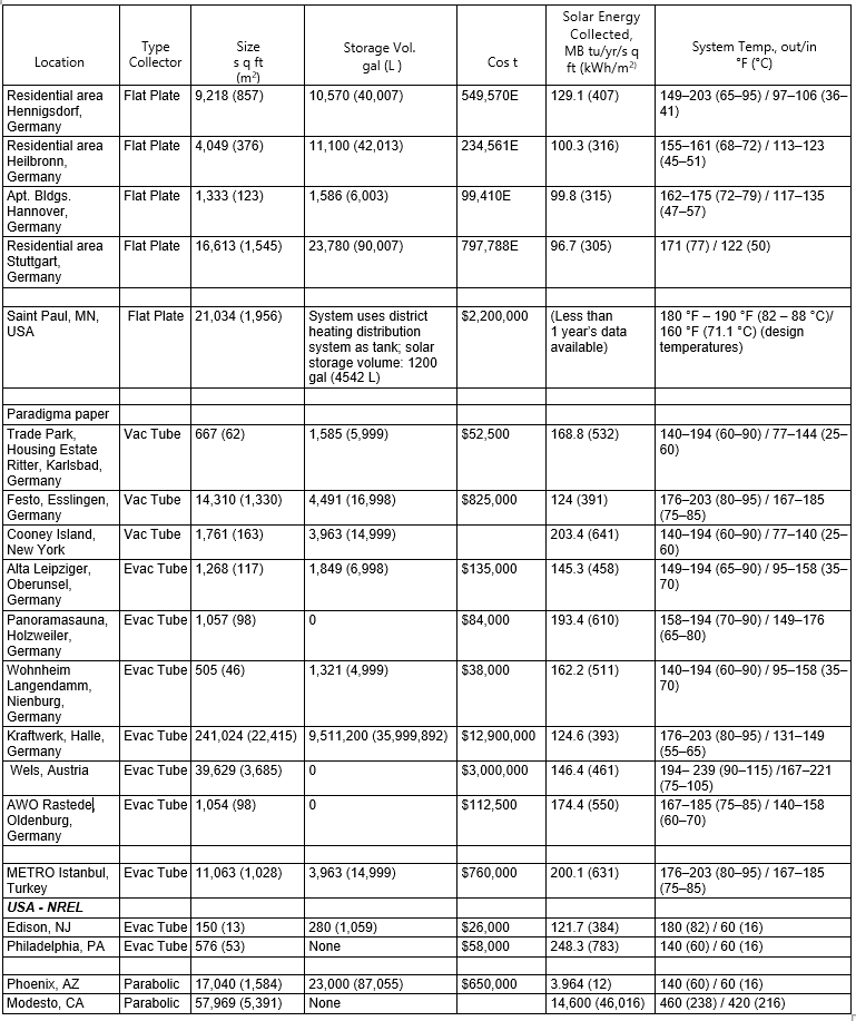
Chapter: 5 Design Considerations
5.1 Collector site placement
In an US Army installation, solar collectors can be placed on building roofs or on the ground adjacent to the buildings they would serve. Rooftop is limited by useful area and maintenance is a greater issue than with ground-placed systems. Access to roof mounted systems is more difficult; stairs or ladders need to be climbed, and space for safe movement between the collectors and the roof edge must be provided and maintained. Ground placement of the collectors can displace green spaces that are desired in building clusters, thus limiting the number of buildings to a given ground area. A compromise may be to place large collector systems above parking spaces in the soldier parking lots so the collectors can shade vehicles, and still remain close to the buildings and to the ground level for ease of maintenance. Figure 5.1 shows solar collectors located in a parking area.
When using a roof placement make sure that the predicted life of the roof is about equal to or longer than that of the solar system. Avoid placing a solar system having a life of 20 yrs on a roof scheduled for replacement in a shorter time.
Increasing the collector field distance to the mechanical room and storage tank increases losses and should always be minimized. The maximum distance should be less than 600 ft (1823 m) one way.
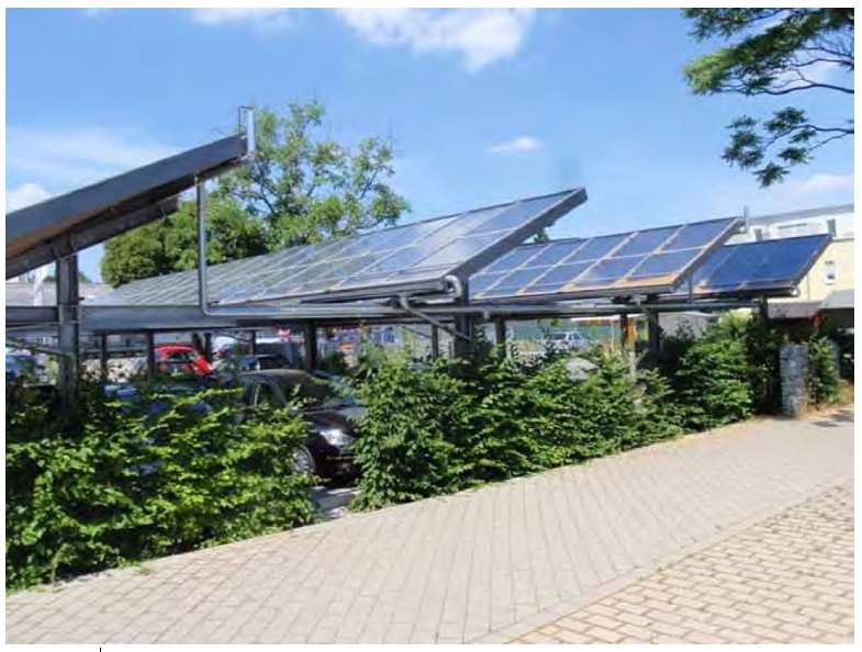
5.2 Structural (foundation)
The support of the rooftop solar collector becomes part of the building’s structural system. For small collectors serving a single wood frame building the collector system can typically be secured directly into the roof rafters. For larger installations more typical of that on US Army barracks, dining facilities, and other buildings, an engineered substructure is generally required to meet local codes and to support the collector arrays. The design object would be to use less material and fewer roof penetrations. Considerations of the supporting structure design are:
- Penetrations though the roof for connection to the existing structure must be water tight using properly sealing methods. Apply insulation where needed.
- Dynamic loads of wind and snowfall (see Figure 5.2) must be included in the structural analysis
- Expansion and contraction of system components must be considered.
- Where geographically required, seismic loads shall also be included in the structural design.
- The system design must provide access for maintenance and safe movement near roof edges.
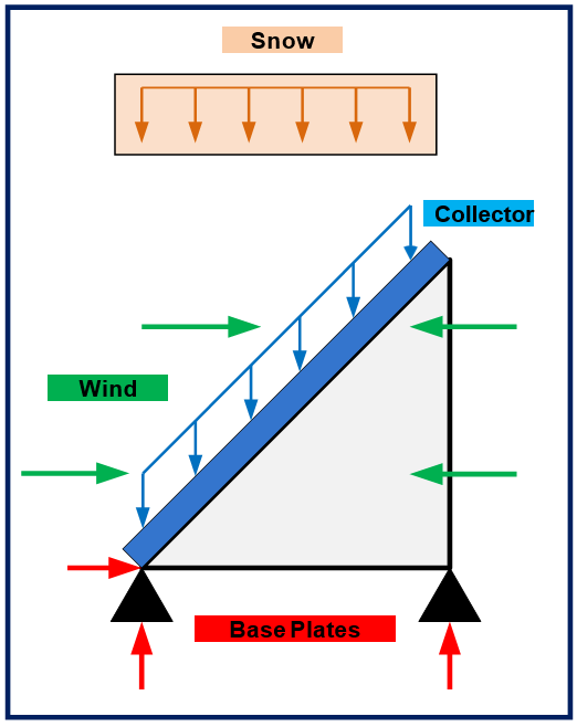
A major concern with the installation of solar collectors is the wind impact on the structure. Increased wind loading on the support substructure can be offset by increasing the securing mounting points and reducing the tilt of the solar collector. A taller solar collector has a greater wind resistance and thus a higher wind load.
A typical engineered substructure supporting the solar collectors consists of beams or open web joists mounted on supports attached to the building structure below the roof. These reasonable spaced attachments are optimized with the cost of the rest of the supporting structure. The cost on a flat roof is ~$10/sq ft (~75.4€/m2). If the use of reasonably spaced support points is not desired, the support structure must span longer distances up to the width of the roof. The cost of using the longer span can approach 2.5 times the structure having intermediate supports. The frame that supports the solar collectors should be made using a non-corrosive metal such as aluminum.
Collectors mounted on sloped roofs typically take the roof slope as their tilt angle. This should be between 20 and 50 degrees. Slopes within this range on a sun facing roof will have only a slight reduction in performance when compared with the optimum tilt angle. These collectors may be attached a few inches above the roof to allow for rain water to flow underneath. Another style of placing solar collectors on a sloped roof is to integrate them into the roof surface. Figure 5.3 shows how these collectors form part of the roof replacing the roof materials being used. Pipe connects directly to the collectors from the ceiling space below. In-roof placement typically requires roofs with a slope of not less than 20 degrees to avoid standing water on the glazing, which may void the manufacturers water tightness guarantee.
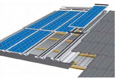
Collectors can also be placed in a vertical wall (Figure 5.4). Flat plate collectors attached to a full surface of the building façade can eliminate the need for insulation and a weatherproof covering for the affected wall area, thus providing avoided cost savings that will offset the reduction in solar energy collection performance.

element.
Collectors placed on flat roofs or the ground need to be arranged so that the optimum performance can be achieved. The materials used for constructing the structural supports need to be protected from corrosion. The use of steel hardware and fasteners in contact with aluminum collector frames and copper piping create a high likelihood of corrosion. Separating dissimilar materials with fluorocarbon polymer, phenolic, or neoprene rubber materials is recommended.
Placement distance between rows must be such that shading of one row by the next row behind is minimized. A slight amount of shading in the winter when the sun is lowest in the horizon can be permitted if the space for collectors is limited or piping costs are a concern since the solar radiation lost is a small percentage of the total annual amount. In areas where snowfall is normal a space of at least 12 in (30.5 cm). between the roof and the lowest collector part should be provided to allow for the collection of snow that has slid off the collectors. There also should be space for safe human movement between the collectors and around the end of collector rows. The space between the roof edge and the collector row must satisfy local building codes. Figure 5.5 shows a diagram of the space between collector rows (located on the ground or flat roofs) when the collectors are placed one behind the other on a horizontal surface.
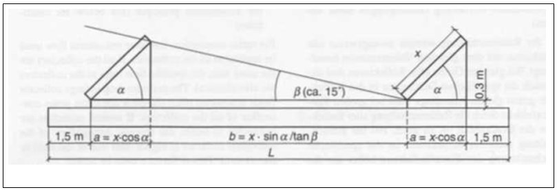
When placing the collector on a roof, care must be taken not to damage the roof surface or interfere with other roof functions. Placement should allow for proper operation roof drains, HVAC and exhaust systems, plumbing vents, flues, or chimneys and antennas. Space for maintenance of the roof and those system placed on the roof shall also be provided. If the roof can handle the addition load of the solar collectors, then the collector supports can be attached to concrete slabs placed on the roof. To avoid harming the roofing below them these pads need to be placed on protective mats. Roof penetrations for structural connections and piping need to be made water tight. This is typically done using sleeves that surround the connecting structural or piping components, and that pass through the roof. A sealant is placed in the sleeve to form a watertight barrier and the top of the sleeve is ~3 in (77 mm). above the probable roof water level. The sleeve is appropriately flashed around for a good weather tight roof penetration. Figures 5.6 to 5.8 show several methods of supporting solar collectors on the ground or on a flat roof. It is advised that the roofing company that installed the roof be used to perform the roof work required to install the solar collector to preserve the remaining roof warranty.
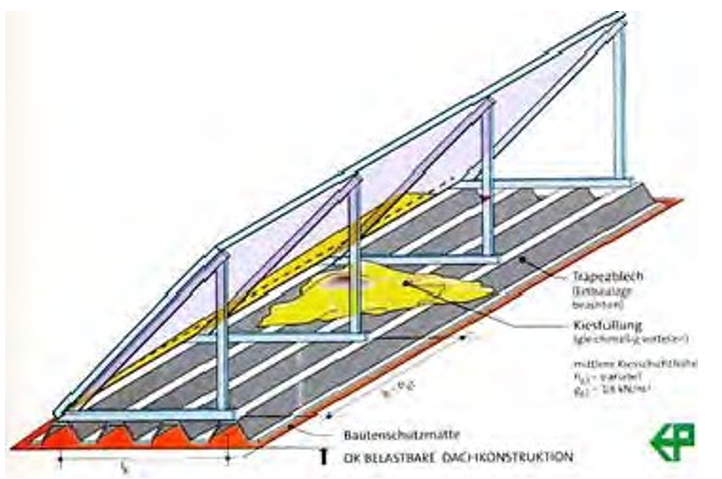
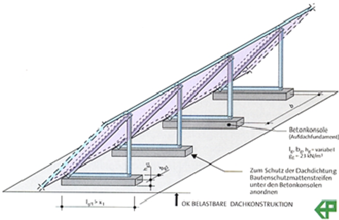
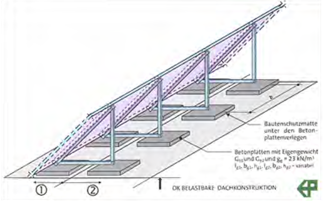
5.3 Mechanical
5.3.1 Piping
Generally Type L copper, black steel and stainless steel are appropriate materials for the piping system. When using copper tubing, hard soldering is recommended for the collector loop. Care must be taken in using Teflon tape to seal threaded pipe joints when water /glycol is being circulated in the pipes. With proper dielectrics, black steel piping can be used on the collector side for use with glycol systems.
All piping shall be sloped at 1/4 in/ft (6.35 mm/0.30 m) of run back to the drain back tank. High points shall be kept to a minimum and combination automatic air vent valve/vacuum breakers shall be placed at all high points. Discharge of automatic air vents shall be piped back to the drain back tank and be provided with an in-line sight glass.
Piping should be designed for low pressure drop and the shortest routes used. All exposed piping should be well insulated with approved weather resistant insulation. Dielectric unions should be used at connections between dissimilar metals. Rubber or silicone hose used for connections must be of a high temperature type. The pipe ends should have ferrules to provide a good seal with the hose.
Pipe sizing should be in accordance with recognized methods. Figure 5.9 shows an example of a pipe layout with sizes for a collector field. The pipe sizes shown are metric sizes for copper tube. The equivalent nominal US copper pipe sizes are:
- 16u = 1/2
- 19u = 5/8
- 29u = 1
- 35u = 1-1/4
- 41u = 1-1/2
- 54u = 2 in.
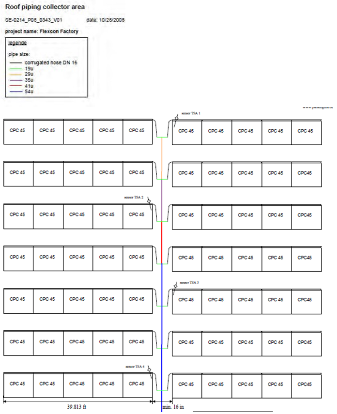
The piping system (valves, pumps, fittings, flanges, connections, and insulation) should be designed to withstand the special conditions caused by the extreme temperatures of stagnation, e.g., 320 °F (160 °C) plus, and frost, e.g., -5 °F (-21 °C); expansion of pipe-length; pressure (e.g., steam) and working fluid (e.g., corrosion). An expansion vessel of sufficient size should also be part of each closed piping network. The system should be designed to operate at a pressure less than 125 psig (861.75 kPa), which will allow the use of standard piping components (class 125). A discussion of system temperatures and pressures is found in Section 3.4.2 “Stagnation” (p 33).
Collector piping must be able to withstand the expansion and contractions of components caused by the changes in temperatures that could be experienced. These temperature changes typically occur daily, which is significantly higher number of cycles than experienced by a normal heating system. The use of offset elbows, high pressure hoses, and expansion couplings should be considered rather than expansion loops unless they are placed horizontally due to drainage difficulties they would create.
Corrosion is a major concern in the solar hot water system. The two types of corrosion that cause the most galvanic damage and pitting corrosion. Solar energy systems generally contain a number of different metals such as aluminum, copper, brass, tin, and steel. This makes the solar system a prime candidate for galvanic corrosion. Heat transfer fluids can contain chemicals and heavy metal ions that would cause local or pit corrosion.
Galvanic corrosion is a type of corrosion caused by an electrochemical reaction between two or more different metals in contact with each other. A chemical reaction between the metals causes a small electrical current that erodes material from one of the metals. If the dissimilar metals are physically joined or if they are contacted by a common storage or heat-transfer fluid, the possibility of galvanic corrosion becomes much greater. Pitting corrosion is a highly localized form of corrosion resulting in deep penetration at only a few spots. This type of corrosion can take years to form, but can be very troublesome since it causes leaks that are difficult to locate.
Pit corrosion occurs when heavy metal ions such as iron or copper plate on a more anodic metal such as aluminum causing a small local galvanic cell can be formed. This corrosion spot or “pit” usually grows downward in the direction of gravity. Pits can occur on vertical surfaces, although this is not as frequent. The corrosion pits may require an extended period (months to years) to form, but once started they may penetrate the metal quite rapidly. Heavy metal ions can either come as a natural impurity in a water mixture heat transfer fluid or from corrosion of other metal parts of the solar system.
Pitting corrosion has the same mechanism (concentration cell) as crevice corrosion. Thus, it can also be aggravated by the presence of chloride or other chemicals that can be part of the water mixture or a contaminant from solder fluxes. Aluminum is very susceptible to pitting corrosion, while copper generally is not.
Several preventive measures will eliminate or at least minimize galvanic and pitting corrosion in collector systems that use an aqueous collector fluid. The best method to prevent galvanic corrosion is to avoid using dissimilar metals. Where this is not possible or practical, the corrosion can be greatly reduced by using nonmetallic connections between the dissimilar metals, thus isolating them. Galvanic protection in the form of a sacrificial anode is another method of protecting the solar system metals. Also, use of similar metals reduces the problems of fatigue failure caused by thermal expansion. Pitting corrosion is essentially eliminated if copper absorber plates are used in the solar collectors. Corrosion inhibitors can minimize pitting corrosion in aluminum absorbers.
When sacrificial anodes are to be used Their placement is important to obtain good protection and it depends on what is being protected, the anode material being used and the electrical conductivity of the heat transfer fluid.
5.3.2 Valves
Valves are used in the solar hot water system for balancing flow, flow adjustment, component isolation, and for temperature and pressure control. These valves should be of the same material as the pipe. At drainage locations of the collector piping ball valves should be used.
For solar collector arrays, the piping design can create nearly equal flow, but a balancing valve may be needed for a final adjustment. Use of these valves should be minimized since their use adds to the pressure drop in the piping system. Each collector array should also have a ball valve at the inlet, and a three-way valve at the outlet, with the third port open to atmosphere for isolation. Use of these valves will allow parts of the system to be taken out service for maintenance, repair, etc. while the remaining parts of the system are operating. These valves can also be used to stop flow as part of a freeze protection plan. Both of these valves are manually operated. The balancing valve should be set during fluid flow system set-up and then fixed at that position.
At heat exchangers, fluid flow adjustment may be necessary to assure the appropriate temperature is being delivered by the solar system components. For example, a mixing valve is used to blend hot water with cooler return water so that a 140 °F (60 °C) domestic hot water is delivered to users. Another example is flow control valves that can be used to direct heated water to the proper height of the storage tank to minimize mixing of different water temperatures. Figures 3.21 through 3.25 show such arrangements.
Valves, other than seasonal or emergency shut-off valves, should be electrically operated and located out of the weather or well protected. A vent must be provided at the high point in liquid systems to eliminate entrapped air and it should also serve as a vacuum breaker to allow draining of the system. To avoid multiple venting, systems should be piped to avoid having more than one high point. Pressure relief by safety relief valves must be provided at some location in each flow circuit that can be isolated by valves. The safety valves must be sized for flow conditions that could occur under stagnation. Check valves can be added to prevent thermally induced gravity circulation. A flow-check valve (used in the hydronic heating industry) will also accomplish the same purpose.
When the solar storage tank contains hot water to be used as DHW, an anti-scald valve is often required on the leaving DHW pipe to limit the outlet temperature, which can reach temperatures of 176 °F (80 °C). Care should be taken to compensate for any pressure drop this valve adds to the DHW circulating piping system.
5.3.3 Strainers and filters
Piping accessories such as fluid strainers and filters are those that would be used with any heating system. They should be place at the inlet of pumps and before control valves.
5.3.4 Fluid pumps
The type pump to be used is a centrifugal type that is used in building heating systems. If the loss of fluid to the environment is a concern a seal-less magnetic drive centrifugal pump should be considered. The pump components (seals, gaskets, bearings, etc.) must be able to withstand hot temperatures that could reach may reach 300 °F (149 °C) for short periods. Basically, three types of pumps are available:
- constant flow pumps
- electronic pressure controlled pumps (variable flow)
- high efficient pressure controlled pumps (variable flow).
Variable speed wet rotor circulators are preferred since they can operate the collectors either at a setpoint, or the most efficient range, while minimizing the electricity used to drive the pump. The use of variable flow is a method for achieving the desired temperature rise of the heat transfer fluid in the solar collectors. If the solar radiation is not very intense, then the fluid flow is reduced, causing the fluid to spend more time in the collector. Figure 5.10 shows the difference in energy use of these different methods of pump operation.
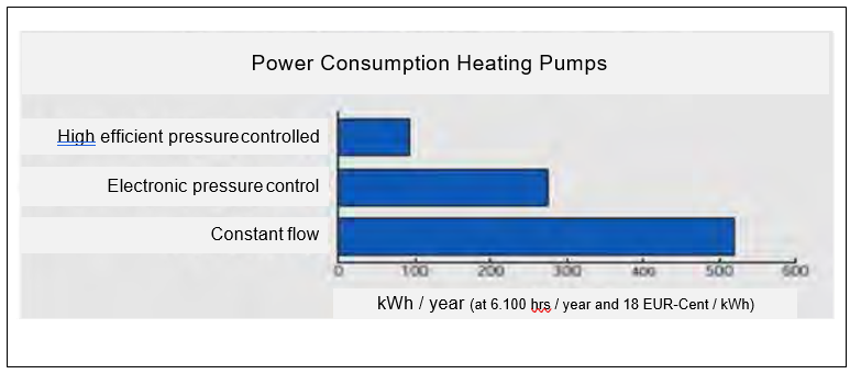
Sizing of the pump is accomplished in the normal way of heating pump selection. An estimate of the flow rate can be made using the common flow rate for the collector field of 0.020m gpm per sq ft of collector area (when using water as the collector fluid). If a 40% glycol mixture at 140 °F (60 °C) is the collector fluid, then the flow rate would be ~10% more than a water solution. For a more accurate value, use of the computer programs identified in Section 4.3.2 (p 58).
If water is the circulated fluid and the system is open to the atmosphere or the water is potable then the pump wetted components should be made from stainless steel or bronze to minimize corrosion. Solar collector pumps should be placed in locations where leakage would not cause serious damage
5.3.5 Type of heat exchangers used
There are two types of heat exchangers to chose from: plate-and-frame, and tube-and-shell. Plate- and-frame heat exchangers are most economical for commercial systems as they take up little space and do not need insulation. They provide the highest approach temperature (the leaving temperature of the secondary fluid compared to the entering temperature of the hotter primary fluid). Plate-and-frame exchangers need very clean surfaces to obtain this performance and thus require a nightly reverse backflush to break free any accumulated deposit on the water side.
Tube-and-shell heat exchangers are a good option for light commercial applications since they are also practical in this setting (in terms of size), and because they have having good resistance to fouling since the water passages are large. The leaving temperature of the secondary fluid will be lower with this type of heat exchanger.
Conversely, water quality also affects system components; for areas with hard water (hardness > 100ppm), a closed loop or water softener should be used.
Generally stainless steel or copper is selected as a material for heat exchanger construction because of their good heat transfer properties and corrosion resistance.
If the heat transfer fluid is not safe for human consumption or is toxic (like ethylene glycol) then a double wall heat exchanger is required. Figure 5.11 shows an example of this type of heat exchanger where a volumetric space is filled with a nontoxic heat transfer fluid between the two circulating fluids.
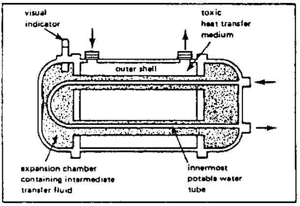
A leak in one side would become visible and the other fluid could not become contaminated. Leak detection would involve noting a change in the fluid level in the interim space or a change in color of the interim fluid. When plate-and-frame heat exchangers are used leak detection can be provided by an additional heat exchanger circulating loop filled with a colored fluid for detection fluid between the glycol used in the collector circulating loop and the domestic water system. A check of the current building code should be made to determine the acceptable method of isolation.
To help minimize pumping energy, the pressure loss of the heat transfer fluids passing through the heat exchanger should be limited to 1 to 2 psi (6.9 to 14 kPa). Heat exchangers used to heat domestic water are exposed to the potable water pressure and thus should be rated for that pressure, typically above 75 psi (517 kPa).
5.3.6 Type storage tank used
The storage tank or tanks for a large hot water heating system should be placed near the solar collectors. These tanks are normally a non-pressurized type, which is open to the atmosphere using a vent in the top cover. The reason for this is the high cost difference of big tanks needed in large solar thermal systems. Pressurized tanks must be ASME rated in accordance with the maximum possible pressures and temperatures. (System designer to reference the requirements of the ASME boiler and pressure vessel Code for determination of requirements.) Non-pressurized systems are allowed and may be necessary to make the system LCCA attractive due to the high cost of ASME rated tanks. In instances where the tanks are non-pressurized, ASME rated tanks are not required. When using a non-pressurized tank, it must be the high point of that circulating fluid system
Domestic hot water storage tanks should be in the building where the hot water is consumed. These tanks would be typically smaller than the system storage tank and should be of a pressurized type. The tank can be piped so its water is warmed by water flowing from the solar heated storage tank and non-solar methods. Here a fossil fuel or electric heater can assure the proper domestic hot water temperature is being maintained.
Storage tanks can be made using steel, fiberglass/plastic, or concrete. Steel tanks make connections with the piping easy, are subject to corrosion; large tanks may require on-site fabrication. Fiberglass/plastic tanks do not corrode, but have a maximum temperature in the range of the temperature that could be expected during stagnation, they cannot be pressurized, and they are more costly. Concrete tanks are low cost, but must be site fabricated, cannot be pressurized, and can make plumbing connections difficult. Steel tanks should be lined with glass, epoxy, or other corrosion resistant material rated for the highest system temperature and working fluid.
Alternatively, stainless steel tanks may be provided. Tank life should be at least 15 yrs.
Fiberglass and plastic tanks are corrosion resistant and easily installed, and are available in many shapes and sizes. Although many commonly fabricated tanks will begin to soften at temperatures above the temperature range of 140 to 160 °F (60 to 71 °C). There are more expensive, specially fabricated tanks available that can withstand temperatures up to 250 °F (121 °C). The types of plastics needed to store large quantities of water at high temperatures can be more expensive than steel.
All storage tanks require insulation with a rating at least R-19.It is a good practice to insulate tank supports from the ground if possible. Additional information on tank insulation can be found in the Solar Energy Equipment Chapter of the ASHRAE Handbook – HVAC Systems and Equipment.
All storage tanks for liquids should be located so that if they leak, damage to the building will be prevented. The drain back tank needs a drain line piped to a nearby floor drain. The cost of housing the tank or burying it must be included in the total cost of the solar heating system. Buried tanks must be protected from ground water, and buoyant forces resisted. Underground tanks are not preferred, if other options are available. Tanks must be reasonably accessible for repairs. Tank connections should comply with local codes with regards to backflow preventers, safety relief valves, etc.
5.3.7 Integration of solar collector system into existing hot water distribution system
Solar water heating systems maximize solar heat production when installed in a preheat configuration, i.e., the cold water supply is redirected to the solar storage tank where it can be preheated, and on a draw, the preheated water is directed into the backup or boiler tank for a final bump to temperature before servicing the usage. Of course this requires operation of the boiler equipment adding to the annual fuel use. Also, the firing rates in this mode may not be in the most efficient firing range of boiler operation.
One method to minimize the back-up boiler operation is to heat the DHW entirely by the solar collectors. One method to accomplish is to recirculate the water leaving the collector again through the collectors if it is not hot enough. This set-up requires a three-way valve between the return and either solar storage tank. This will allow the heat transfer fluid warmed by the collector to be directed either to the storage tank or to the line going back to the solar collectors. The control logic is when the solar tank temperature is higher than the return of the recirculation water; the solar collectors can heat it up further. When the solar tank temperature is below the temperature of the heat transfer fluid leaving the collector, it is directed to the tank.
5.3.8 Controls
There should be an automatic control system that senses system performance and properly transfers collected heat to the intended users. Since the amount of heat being collected can vary as does the demand for heat by the users, the control system must tract both of these variables and operate the systems equipment to achieve the maximum performance. The control system accomplishes this by taking information from sensors and, through the controllers, operates pumps, adjusts valves, and activates the auxiliary heating system.
To correctly monitor the solar hot water system, is important to understand system operation and to maintain good efficiencies. The collection of operational data will assist in the tracking of system performance and aid in scheduling system maintenance. This monitored information shall be collected every day of the year on 15-minute interval. All monitor systems should be centrally monitored for consistency; operating personnel must maintain a familiarity with the hardware and software, and the system must be properly managed through trend tracking and effective dispatching of service personnel. The minimum monitoring points are:
- tank temperature
- solar array circulating pump start/stop
- solar array circulating pump status
- solar controller alarm
- solar array inlet temperature
- solar array discharge temperature
- solar array discharge temperature alarm high
The temperature sensors that measure the collector discharge temperature should be monitor the absorber plate temperature near the collector outlet. The storage tank temperature should be at the tank bottom to obtain the coldest temperature. These sensors send this collected information to a controller called a differential temperature thermostat, which then compares it with the adjustable setpoints – usually the high and low values. When the high value is reached (typically 12 °F to 15 °F (-11 to -9.44 °C) an action to withdraw the heat from the collector is initiated; for example starting a pump. As the pump runs the temperature differential drops and after some period of time the low setpoint is reached (typically 4 °F [-15.56 °C]). At this temperature difference, the pump is stopped. The pump is restarted when the high limit of the thermostat is again reached.
When a system has freeze and/or overheating protection, the controller takes the appropriate actions. For example, when freeze setpoint is reached at the collector, the pump could be activated to pump warm water from the storage tank into the collector. The freeze protection setpoint should be set at 40 °F (4 °C) since heat can radiate from the collector to the night sky creating collector freezing conditions above 32 °F (0 °C) outdoor temperatures. The freeze protection sensor must be placed on the collector so that it will sense the coldest water in the collector. This location may be the collector intake or return manifold, the back of the absorber plate near the bottom or center of the collector. The collector center is identified to monitor the irradiation leaving the collector at night. More than one sensor can be used for this function.
The energy produced by solar energy shall be determined by a Btu meter that will measure the domestic hot water flow from the storage tank, the incoming cold make-up water temperature, and the hot water temperature leaving the domestic hot water storage tank. These values should be continually evaluated and compared to previous values to assure proper performance is maintained.
Overheating controls would be initiated when the collector temperature reaches a temperature in the range of 200 to 250 °F (93 to 121 °C) depending on the system. The sensor monitoring this condition would be placed on the back of an absorber plate in the collector. When the collector reaches the high temperature setpoint due to a pump failure or some other event, the controller can take actions to relieve the heat and protect the system. See section 2.4.2 for more information.
The control components are the same that would be used on a commercial hot water heating system.
A typical sequence of operation for the operation of the solar collector circulation pump that sends water to the storage tank is:
- System run command: If solar array temperature is above the solar tank temperature by 12 °F (-11 °C), energize solar collector circulation pump P-1. Pump shall be energized during daylight hours only. On command to start, pump must remain energized for an adjustable period of time (initial setting of 20 minutes).
- System stop command (high temperature): If solar collector circulation pump P-1 is energized and if solar storage tank temperature rises above 185 °F (85 °C) (adjustable), activate a high temperature alarm. If solar storage tank temperature rises above 195 °F (91 °C) (adjustable), de-energize solar circulation pump P-1.
- System stop command (low temperature): If solar collector circulation pump P-1 is energized and solar array discharge temperature falls below the solar tank temperature for a period of 10 minutes (adjustable), solar collector circulation pump shall de-energize.
- Thermal shock prevention:If solar circulation pump P-1 is de-energized during daylight hours and if solar array temperature is below 180 °F (82 °C) (adjustable), solar circulation pump shall be enabled.
If solar circulation pump P-1 is de-energized and if solar array temperature is 180 °F (82 °C) or above (adjustable), solar circulation pump P-1 shall be disabled for an adjustable time period (8 hr initial setting).
The sequence of control assumes a constant speed pump circulating the heat transfer fluid through the collectors. If a variable speed pump is used, then the pump speed could be altered instead of stopping and starting the pump. Of course the pump operation would be stopped when night begins and when excessive temperatures are reached in the collector. Another option would have a three- way valve that would allow the heat transfer fluid to circulate through the collector again if it is not hot enough to be placed in the storage tank.
5.4 System startup considerations
All pumps, valves and sensors need to be checked for proper operation before starting of fluid flow systems.
5.4.1 Method of filling system and removal of air
Before filling the piping systems with heat transfer fluids the pipes need to be flushed to remove any foreign material and debris. A high head, low flow filling pump will produce the best results. For commercial systems, the arrays must be staggered so air can be methodically purged from the system.
5.4.2 Method of leak detection
On completion of the piping system, it should be pressure tested for leaks. All piping systems should always include a pressure gauge (digital or dial) for monitoring the fluid pressure. The system should be filled first with water and put under pressure of 1½ times the operating pressure for a minimum of 2 hrs, while the pressure is monitored and the distribution is inspected for leaks. The leak inspection should be completed before installing any piping insulation.
Chapter: 6 System Maintenance
6.1 General maintenance
Operation and maintenance (O&M) costs of each solar water heating system is estimated at ½ of 1% of initial cost per year. O&M is similar to that required of any hydronic heating loop and may be provided by site staff, with experts called in if something should fail. Regularly scheduled maintenance includes:
- Check the solar collectors and structure components for any damage. Note location of panel glazing or broken evacuated tubes needing replacement. Note any surface damage on absorber panel and that tubing containing heat transfer fluid is in good condition.
- Check tightness of mounting connectors. Repair any bent or corroded mounting components.
- Drain energy storage tanks for sediment removal.
- Check condition of heat transfer fluids.
- Determine if any new objects, such as vegetation growth, are causing shading of the array and remove them if possible.
- Clean outer surface of collector array annually with plain water or mild dishwashing detergent. Do not use brushes, any types of solvents, abrasives, or harsh detergents.
- Check all connecting piping for leaks. Repair any damaged components.
- Check plumbing for signs of corrosion
- Check condition of corrosion inhibitors in heat transfer fluids and the state of the sacrificial anodes in the system.
- Observe operational indicators of temperature and pressure to ensure proper operation of pumps and controls.
- Observe that the collector heat transfer fluid pump is running on a sunny day and not at night.
- Use insolation meter to measure incident sunlight and simultaneously observe temperature and energy output values given by system controller. Compare the values with original efficiency of system.
- Check status indicators provided by system controller. Compare indicators with measured values.
- Document all operation and maintenance activities in a workbook available to all service personnel.
- Check proper position of all valves
- Flush entire piping system to remove mineral deposits every 10
A more through checklist can be found in the Solar Energy Use Chapter of the ASHRAE Handbook — HVAC Applications.
6.2 Glycol fluid care
The decomposition rate of glycol varies according to the degree of aeration, high temperature exposure and the service life of the solution. Most water/glycol solutions require periodic monitoring of the pH level and the corrosion inhibitors. The pH should be maintained between 6.5 and 8.0.
Replacement of the water/glycol solution may be as often as every 12–24 months or even sooner in high temperature systems. If these solutions are used in the collector loop, the installer should specify the expected life of the solution and the amount of monitoring required. The cost of periodic fluid replacement and monitoring should be considered in the economic analysis. For best performance, the glycol should be replaced every few years. Since glycol-water mixtures do require a lot of maintenance (and since users can be quite negligent) it is recommended that glycols not be used in family housing solar heating and DHW systems, and that glycol-water solutions be reserved for use in large-scale installations, which have regular maintenance schedules.
