Introduction to Compressed Air Systems
This section of the course is intended for readers who want to gain an understanding of the basics of industrial compressed air systems.
Compressed air is widely used throughout manufacturing industries and is often considered the “fourth utility” at many facilities. Almost every industrial plant, from a small machine shop to an immense pulp and paper mill, has some type of compressed air system. In many cases, the compressed air system is so vital that the facility cannot operate without it. Plant air compressor systems can vary in size from a small unit of 5 horsepower (hp) to huge systems with more than 50,000 hp.
In many industrial facilities, air compressors use more electricity than any other type of equipment. Inefficiencies in compressed air systems can be significant. Energy savings from system improvements can be substantial, resulting in thousands, or even hundreds of thousands of dollars of potential annual savings, depending on use. A properly managed compressed air system can save energy, reduce maintenance, decrease downtime, increase production throughput, and improve product quality
Compressed air systems consist of a supply side and a demand side. The supply side includes compressors and air treatment (dryers and filters). The demand side includes distribution and end-use equipment. A properly managed supply side will result in clean, appropriately dried, stable air being delivered at the appropriate pressure in a dependable, cost-effective manner. A properly managed demand side minimizes wasted air and uses compressed air for appropriate applications. Improving and maintaining peak compressed air system performance requires addressing both the supply and demand sides of the system and how the two interact.
Components of an Industrial Compressed Air System
A compressor is a machine that is used to increase the pressure of a gas. The earliest compressors were bellows, used by blacksmiths to intensify the heat in their furnaces. The first industrial compressors were simple, reciprocating piston-driven machines powered by a water wheel.
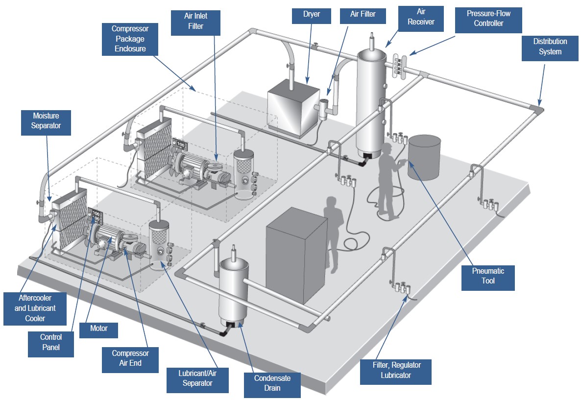
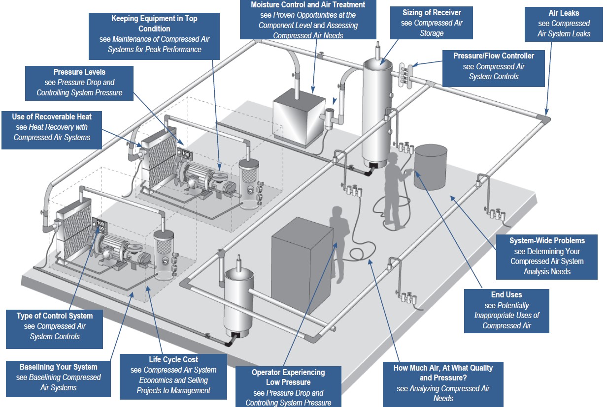
A modern industrial compressed air system is composed of several major sub-systems. Major sub-systems include the compressor, prime mover, controls, treatment equipment and accessories, and the distribution system. The compressor is the mechanical device that takes in ambient air and increases its pressure. The prime mover powers the compressor. Controls serve to regulate the amount of compressed air being produced. The treatment equipment removes contaminants from the compressed air, and accessories keep the system operating properly. Distribution systems are analogous to wiring in the electrical world—they transport compressed air to where it is needed. Compressed air storage can also serve to improve system performance and efficiency. Figure 1.1 shows a representative industrial compressed air system and its components.
Compressor Types
Many modern industrial air compressors are sold “packaged” with the compressor, drive motor, and many of the accessories mounted on a frame for ease of installation. Provision for movement by forklift is common. Larger packages may require the use of an overhead crane. An enclosure may be included for sound attenuation and aesthetics.
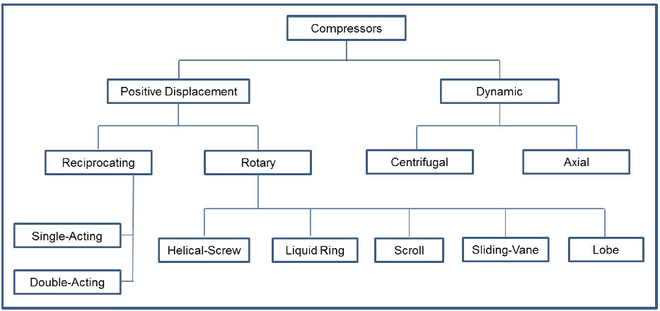
As shown in Figure 1.2, there are two basic compressor types: positive-displacement and dynamic. In the positive-displacement type, a given quantity of air or gas is trapped in a compression chamber and the volume which it occupies is mechanically reduced, causing a corresponding rise in pressure prior to discharge. At constant speed, the air flow remains essentially constant with variations in discharge pressure. Dynamic compressors impart velocity energy to continuously flowing air or gas by means of impellers rotating at very high speeds. The velocity energy is changed into pressure energy both by the impellers and the discharge volutes or diffusers. In the centrifugal-type dynamic compressors, the shape of the impeller blades determines the relationship between air flow and the pressure (or head) generated.
Positive Displacement Compressors
These compressors are available in two types: reciprocating and rotary. Reciprocating compressors work like bicycle pumps with the exception that an electric motor replaces the human energy source. A piston, driven through a crankshaft and connecting rod by an electric motor, reduces the volume in the cylinder occupied by the air or gas, compressing it to a higher pressure. Single- acting compressors have a compression stroke in only one direction, while double-acting units provide a compression stroke as the piston moves in each direction. Large, industrial reciprocating air compressors are double-acting and water-cooled. Multi-stage, double- acting compressors are the most efficient compressors available, and are typically larger, noisier, and more costly than comparable rotary units. Reciprocating compressors are available in sizes from less than 1 hp to more than 600 hp.
Rotary compressors have gained popularity and are now the “workhorse” of American industry. They are most commonly used in sizes from about 10 to 500 hp. The most common type of rotary compressor is the helical-twin, screw-type (also known as rotary screw or helical-lobe). Male and female rotors mesh, trapping air, and reducing the volume of the air along the rotors to the air discharge point. Rotary screw compressors have low initial cost, compact size, low weight, and are easy to maintain. Rotary screw compressors may be air- or water-cooled. Less common rotary compressors include sliding-vane, liquid-ring, and scroll-type.
Single-Acting, Reciprocating Air Compressors
This type of compressor is characterized by its “automotive” type piston driven through a connecting rod from the crankshaft. Compression takes place on the top side of the piston on each revolution of the crankshaft. Single-acting, reciprocating air compressors are generally air-cooled. These may be single- stage, usually rated at discharge pressures from 25 to 125 pounds per square inch gauge (psig), or two-stage, usually rated at discharge pressures from 125 psig to 175 psig or higher.
The most common air compressor in the fractional and single-digit hp sizes is the air-cooled, reciprocating air compressor. Single-acting reciprocating compressors above 30 hp are much less common. Two-stage and multi-stage designs include inter-stage air-cooling to reduce air temperatures to the second stage for improved efficiency and durability.
Pistons used in single-acting compressors are of the “automotive” or “full skirt” design, the underside of the piston being exposed to the crankcase. Lubricated versions have a combination of compression and lubricant-control piston rings, which seal the compression chamber, control the lubricant to the compression chamber, and act (in some designs) as support for piston movement on the cylinder walls.
Lubricant-free, or non-lube designs, do not allow lubricant in the compression chamber and use pistons of self-lubricating materials or use heat resistant, non-metallic guides and piston rings that are self- lubricating. Some designs incorporate a distance piece or crosshead to isolate the crankcase from the compression chamber.
Lubricant-less (or oil-less) designs have piston arrangements similar to lubricant-free versions, but do not have lubricant in the crankcase. Generally these have greased pre-packed crankshafts and connecting rod bearings.
Cooling. Single-acting air compressors have different arrangements for removing the heat of compression. Air-cooled versions have external finning for heat dissipation on the cylinder, cylinder head, and in some cases, the external heat exchanger. Air is drawn or blown across the fins and the compressor crankcase by a fan, which may be the spokes of the drive
pulley/flywheel.
Liquid-cooled compressors have jacketed cylinders, heads and heat exchangers, through which liquid coolant is circulated to dissipate the heat of compression. Water, or an ethylene glycol mixture to prevent freezing, may be employed.
Drives. The most common drive arrangement is a belt drive from an electric motor. The compressor sheave also acts as a flywheel to limit torque pulsations and its spokes often are used for cooling air circulation. Belt drives allow a great degree of flexibility in obtaining the desired speed of rotation.
Flange-mounted, or direct-coupled motor drives provide compactness and minimum drive maintenance. Belts and couplings must be properly shielded for safety and to meet Occupational Safety & Health Administration (OSHA) requirements.
Double-Acting, Reciprocating Air Compressors
Double-acting reciprocating compressors use both sides of the piston for air compression, almost doubling the capacity for a given cylinder size. A piston rod is attached to the piston at one end and to a crosshead at the other end. The crosshead ensures that the piston travels concentrically within the cylinder. These compressors may be single- or multi-stage, depending on discharge pressure and hp size. These are generally available in larger horsepower sizes.
Cooling. Double-acting air compressors generally have cooling water jackets around the cylinder body and in the cylinder head. This, combined with their relatively slow speed of operation and water-cooled intercooling, results in excellent compression efficiency.
Lubrication. Cylinder lubrication is generally by means of a pressure or vacuum-feed cylinder lubricator, with a feed rate of several drops per minute, depending on cylinder size and piston speed and as specified by the manufacturer. Lubricant-free versions also are available with polytetrafluorethylene (PTFE) or similar materials for pistons, riders, and compression rings. A distance piece is provided between the crankcase and the cylinder(s) to ensure that no part of the piston rod, which enters the lubricated crankcase, can enter the lubricant-free cylinder area.
Balance. Single- and two-cylinder compressors of this type generally require a substantial foundation due to unbalanced reciprocating forces.
Drives. Below 200 hp, belt drives and flange-mounted induction motors are normally used. For motors larger than 300 hp, flange-mounted, synchronous motors are sometimes used with a 1.0 power factor or 0.8 leading power factor to provide power factor correction to off- set other induction-type electrical loads.
Lubricant-Injected Rotary Screw Compressors
The lubricant-injected rotary screw compressor powered by an electric motor has become a dominant type of industrial compressor for a wide variety of applications.
Compression Principle. The lubricant-injected, rotary- screw compressor consists of two intermeshing rotors in a machined housing (Rotor Housing) having an inlet port at one end and a discharge port at the other. The male rotor has lobes formed helically along its length while the female rotor has corresponding helical grooves or flutes. The number of helical lobes and grooves may vary in otherwise similar designs.
Air flowing in through the inlet port fills the spaces between the lobes on each rotor. Rotation then causes the air to be trapped between the lobes and the rotor housing as the inter-lobe spaces pass beyond the inlet port. As rotation continues, a lobe on one rotor rolls into a groove on the other rotor and the point of intermeshing moves progressively along the axial length of the rotors. This reduces the space occupied by the air, resulting in increased pressure. Compression continues until the inter-lobe spaces are exposed to the discharge port when the compressed air is discharged.
Lubricant is injected into the compression chamber during compression and serves three basic functions: 1) lubrication for the intermeshing rotors and associated bearings; 2) removal of the heat caused by compression; and 3) seals the clearances between the meshing rotors and between rotors and rotor housing.
Lubrication. The generic term “lubricant” has been used instead of oil. The lubricant may be a hydrocarbon product, but most compressors now use cleaner and longer life synthetic lubricants, including diesters, polyglycols, polyalphaolefins, polyol esters, and silicone- based lubricants. These newer products are suitable for a wider range of temperatures.
A mixture of compressed air and injected lubricant leaves the air end and is passed to a sump/separator where the lubricant is removed from the compressed air. Directional and velocity changes are used to separate most of the liquid. The remaining aerosols in the compressed air, then are separated by means of an air/lubricant separator or a coalescing filter, resulting in only a few parts per million (ppm) of lubricant carry-over (usually in the range of 2 to 5 ppm). A minimum pressure device, often combined with a discharge check valve, prevents excessive velocities through the separator element until a normal system pressure is achieved at start-up. Most lubricant-injected rotary screw compressor packages use the air pressure in the lubricant sump/separator, after the discharge of the air end, to circulate the lubricant through a filter and cooler prior to reinjection to the compression chamber. Some designs may use a lubricant pump.
Multi-stage compressors. Multi-stage compressors have different manufacturing designs. Multiple stages are used either for improved efficiency at a given pressure or to achieve higher pressures.
Cooling. The temperature of the lubricant injected into the compression chamber is generally controlled directly or indirectly to a minimum temperature by controlling the discharge temperature. A thermostatic bypass valve allows some or all of the lubricant being circulated to bypass the lubricant cooler to maintain the desired temperature over a wide range of ambient temperatures.
Generally, suitable lubricant temperature and viscosity are required for proper lubrication, sealing, and to avoid condensation in the lubricant sump. It also is necessary to avoid excessive temperatures, which could result in a breakdown of the lubricant and reduced life.
In addition to lubricant cooling, an aftercooler is used to cool the discharged air and a moisture separator with an automatic drain trap removes the condensate. In the majority of applications, air-cooled, radiator-type lubricants and air coolers are employed and provide the opportunity for heat recovery from the compression process for facility heating. In water-cooled designs, water-cooled heat exchangers with water control valves also are available on most rotary screw compressor packages.
Single-stage, lubricant-injected, rotary screw compressor packages are available from 3 to 900 hp, or 8 to 5000 cubic feet per minute (cfm), with discharge pressures from 50 to 250 psig. Two-stage versions can reduce specific power and some can achieve discharge pressures up to 500 psig. Lubricant-injected, rotary screw vacuum pumps also are available from 80 to 3,100 inlet cfm and vacuum to 29.7 inches Hg. Lubricant-injected, rotary-vane compressors are a less common type of rotary compressor and are available in a limited size range.
Air/Lubricant Separators. The air/lubricant separator in a lubricant-cooled, rotary screw compressor generally starts with a 2 to 3 psid pressure drop at full-load when new. Higher pressure differentials cause the compressor motor to consume more energy and possibly exceed the service factor. Maintenance manuals usually suggest changing them when there is a 10 to 12 psid pressure drop across the separator. In many cases it may make sense to make an earlier separator replacement, especially if electricity prices are high.
Lubricant-Free Rotary Screw Compressors
The principle of compression in lubricant-free rotary screw compressors is similar to that of the lubricant-injected rotary screw compressors but, without lubricant being introduced into the compression chamber. Two distinct types are available: the dry type and the water-injected type.
In the dry type, the intermeshing rotors are not allowed to touch and their relative positions are maintained by means of lubricated timing gears external to the compression chamber. Since there is no injected fluid to remove the heat of compression, most designs use two stages of compression with an intercooler between the stages and an aftercooler after the second stage. The lack of a sealing fluid also requires higher rotation speeds than for the lubricant-injected type. Dry-type, lubricant-free rotary screw compressors have a range from 25 to 4,000 hp or 90 to 20,000 cfm. Single-stage units operate up to 50 psig, while two-stage can generally achieve up to 150 psig.
In the water-injected type, similar timing gear construction may sometimes be used, but water is injected into the compression chamber to act as a seal in internal clearances and to remove the heat of compression. This may allow pressures in the 100 to 150 psig range to be accomplished with only one stage. The injected water, together with condensed moisture from the atmosphere, is removed from the discharged compressed air by a conventional moisture separation device. Similar to the lubricant-injected type, lubricant-free rotary screw compressors generally are packaged with all necessary accessories.
Lubrication. Lubricant-free rotary screw compressors utilize lubricant for bearings and gears, which are isolated from the compression chamber. The lubricant also may be used for stator jacket cooling in air-cooled units. Typically, a lubricant pump is directly driven from a shaft in the gearbox, assuring lubricant flow immediately at start-up and during run-down in the event of power failure. A lubricant filter, typically with 10 micron rating, protects bearings, gears, and the lubricant pump from damage.
Cooling. The cooling system for the dry-type, lubricant-free rotary screw compressor normally consists of an air cooler after each stage and a lubricant cooler. These may be water-cooled or air-cooled, radiator-type. Some older two-stage designs also employ an additional heat exchanger to cool a small portion of the compressed air for recycling to the compressor inlet during the unloaded period.
Dynamic Compressors
Dynamic compressors can be categorized as centrifugal or axial. The centrifugal-type is the most common and is widely used for industrial compressed air. Each impeller, rotating at high speed, imparts radial flow to the air or gas, which then passes through a volute or diffuser. Some large manufacturing plants use centrifugal compressors for both base loading and trimming, while in other facilities, plants use other compressor types to accommodate demand load swings while the dynamic centrifugal compressors handle the base load.
Axial compressors consist of a rotor with multiple rows of blades and a matching rotor housing with rows of stationary vanes. The rotating blades impart energy to the air, primarily in an axial plane. The stationary vanes then act as a diffuser to convert the residual kinetic energy into potential energy by increasing the pressure. This type of compressor is restricted to very high flow capacities. Mixed flow compressors have impellers and rotors which combine the characteristics of both axial and centrifugal compressors.
Centrifugal Air Compressors
A centrifugal air compressor has a continuously flowing air stream which has kinetic energy, imparted to it by an impeller, or impellers, which rotate at speeds that can exceed 50,000 revolutions per minute (rpm). Approximately one half of the energy is developed in the impeller with the other half achieved by converting the velocity energy to pressure energy as the air velocity is reduced in a diffuser and volute.
The most common centrifugal air compressor is one with two to four stages for pressures in the 100 to 150 psig range. A water-cooled intercooler and separator between each stage returns the air temperature to approximately ambient temperature and removes condensed moisture before entering the next stage. An aftercooler cools the air from the final stage and a moisture separator with an automatic drain removes the moisture prior to air delivery to distribution. Air-cooled centrifugal compressors are available within a limited size range.
The inherent characteristic of centrifugal air compressors is that as system pressure decreases, the compressor’s flow capacity increases. The steepness of the pressure head/capacity curve is dependent upon the design of the impellers and diffusers.
Most standard industrial centrifugal air compressor packages are designed for an ambient temperature of 95°F and near sea level barometer pressure. The dynamic nature of the centrifugal compressor results in the pressure head generated by each impeller increasing as the air density increases. The compressor mass flow and actual cubic feet per minute capacity at a given discharge pressure increases as the ambient temperature decreases, provided the motor can support the increased power requirements.
Typically, a capacity control system is provided with the compressor to maintain the desired capacity and to operate within the motor horsepower limits. The control system regulates the air flow by means of an inlet throttle valve or inlet guide vanes. The minimal throttle point is established to prevent flow reversal thru an impeller/diffuser stage, which is also known as surge. Control systems either unload the compressor or blow off the excess air to atmosphere to avoid surge, which could result in excessive vibration and potential damage to the compressor. Given adequate storage, some manufacturers will operate the compressor controls in a load/unload mode at lower flow conditions.
Centrifugal air compressors range from around 200 to more than 100,000 cfm, but the more common air compressors are from 1,200 to 5,000 cfm and with discharge pressures up to 125 psig. These may have several impellers in line on a single shaft or with separate impellers integrally geared.
Centrifugal air compressors provide lubricant-free air delivery as there is no lubricant in the compression chambers. Lubrication for speed increasing gears and the special high-speed shaft bearings is kept away from the compression chambers by means of shaft seals, which may also have air purge and vent connections.
Centrifugal air compressors are high-speed rotating machines and as such, shaft vibration monitoring is mandated to record operational trends and protect the equipment. Automatic control of the compressors is typical and has been greatly improved by the use of microprocessors, which monitor the pressure, capacity, temperature characteristics and main-drive motor current draw. It is important that the manufacturer’s recommended maintenance procedures be followed and that certain maintenance procedures be carried out by qualified staff. This is particularly true of attempts to remove an impeller from its shaft, since special procedures and tools may be involved.
Lubrication and Lubrication Systems. Centrifugal compressors use a pressure lubrication system for bearings and drive gears. The main lubricant pump may be driven from the gearbox input shaft with an electric motor-driven auxiliary lubricant pump for pre-lubrication prior to start-up and for post-lubrication during a cool down period. A water-cooled lubricant cooler is also included.
Because of the high rotation speeds, some designs use a high-pressure lubricant supply to the special bearings involved. The manufacturer’s recommended lubricant should be used and changed at the specified intervals.
Compressor Prime Movers
The prime mover is the main power source providing energy to drive the compressor. The prime mover must provide enough torque and power to start the compressor, accelerate it to full speed, and keep the unit operating under various design conditions. This power can be provided by any one of the following sources: electric motors, diesel or natural gas engines, steam turbines and combustion turbines. Electric motors are by far the most common type of prime mover.
Electric motors are a widely available and economical means of providing reliable and efficient power to compressors. Most compressors use standard, polyphase induction motors. In many cases, either a standard- or a premium-efficient motor can be specified when purchasing a compressor or replacement motor. The incremental cost of the premium efficient motor is typically recovered in a very short time from the resulting energy savings. When replacing a standard motor with a premium-efficient version, careful attention should be paid to performance parameters, such as full-load speed and torque. A replacement motor with performance as close as possible to the original motor should be used. Most new motors are suitable for inverter duty applications.
Diesel or natural gas engines are common compressor power sources in the oil and gas industries. Considerations such as convenience, cost, and the availability of liquid fuel and natural gas play a role in selecting an engine to power a compressor. Although the majority of industrial compressed air systems use electric motors for prime movers, in recent years there has been renewed interest in using non-electric drives, such as reciprocating engines powered by natural gas, particularly in regions with high electricity rates.
Standby or emergency compressors may also be engine-driven to allow operation in the event of a loss of electrical power. Maintenance costs for engine-driven systems are significantly higher than those that use electric motors.
The oldest method of driving compressors is through the use of a steam engine or turbine. In general, how- ever, it is not economical to use a steam engine or turbine unless the steam is inexpensively and readily available within the plant for use as a power source.
Compressed Air System Controls
Compressed air system controls serve to regulate the pressure by matching compressor supply with system demand. Proper compressor control is essential to efficient operation and high performance. Because compressor systems are typically sized to meet a system’s maximum demand, a control system is almost always needed to reduce the output of the compressor during times of lower demand. Compressor controls are typically included in the compressor package, and many manufacturers offer more than one type of control technology. Systems with multiple compressors use more sophisticated controls (network or system master controls) to orchestrate compressor operation and air delivery to the system.
Network controls use the on-board compressor controls’ microprocessors linked together to form a chain of communication that makes decisions to stop/start, load/unload, modulate, vary displacement, and vary speed. Usually, one compressor assumes the lead with the others being subordinate to the commands from this compressor.
System master controls coordinate all of the functions necessary to optimize compressed air as a utility. System master controls have many functional capabilities, including the ability to monitor and control all components in the system, as well as trending data, to enhance maintenance functions and minimize costs of operation. Other types of controllers, such as pressure/flow controllers, may also improve the performance of some systems.
The type of control system specified for a given system is largely determined by the types of compressors being used and the facility’s demand profile. If a system has a single compressor with a very steady demand, a simple control system may be appropriate. On the other hand, a complex system with multiple compressors, varying demand, and many types of end uses will require a more sophisticated control strategy. In any case, careful consideration should be given to compressor system control selection because it can be the most important single factor affecting system performance and efficiency. For information about efficiency and compressor controls, see the Tip titled Compressed Air System Controls in Section 2.
Introduction to Compressed Air Systems – Accessories
Accessories
Accessories are the various types of equipment used to treat compressed air by removing contaminants such as dirt, lubricant, and water; to keep compressed air systems running smoothly; and to deliver the proper pressure and quantity of air throughout the system. Accessories include remote aftercoolers, filters, separators, dryers, heat recovery equipment, lubricators, pressure regulators, air receivers, and condensate drain traps.
Air Inlet Filters. An air inlet filter protects the compressor from atmospheric airborne particles. Further filtration is typically needed to protect equipment downstream of the compressor.
Compressor Cooling. Air or gas compression generates heat. As a result, industrial air compressors that operate continuously generate substantial amounts of heat. Compressor units are cooled with air, water, and/or lubricant. Single-acting reciprocating compressors are typically air-cooled using a fan, which is an integral part of the belt-drive flywheel. Cooling air blows across finned surfaces on the outside of the compressor cylinder’s cooling fins. Larger, water-cooled, double- acting reciprocating air compressors have built-in cooling water jackets around the cylinders and in the cylinder heads. The temperature of the inlet water and the design and cleanliness of the cooler can affect overall system performance and efficiency. Centrifugal compressors are generally water-cooled.
Lubricant-injected rotary compressors use the injected lubricant to remove most of the heat of compression. In air-cooled compressors, a radiator-type lubricant cooler is used to cool the lubricant before it is reinjected. The cooling fan may be driven from the main motor-drive shaft or by a small auxiliary electric motor. In plants where good quality water is available, shell and tube heat exchangers generally are used. Sometimes this heat can be recovered and used for other purposes.
Intercooling. Most multi-stage compressors use intercoolers, which are heat exchangers that remove the heat of compression between the stages of compression. Intercooling affects the overall efficiency of the machine.
Aftercoolers. As mechanical energy is applied to a gas for compression, the temperature of the gas increases. Aftercoolers are installed after the final stage of compression to reduce the air temperature. As the air temperature is reduced, water vapor in the air is condensed, separated, collected, and drained from the system. With cooler water temperatures, most of the condensate from a compressor with intercooling is removed in the intercooler(s), and the remainder in the aftercooler. Almost all industrial systems, except those that supply heated process air require aftercooling. In some systems, aftercoolers are an integral part of the compressor package, while in other systems the aftercooler is a separate piece of equipment. Some systems have both.
Moisture Separators. Moisture separators are devices that remove liquids entrained in the air or gas. A separator generally is installed following each intercooler or aftercooler to remove the condensed moisture. This involves changes in direction and velocity and may include impingement baffles. Lubricant-injected rotary compressors have an air/lubricant coalescing separator immediately after the compressor discharge to separate the injected lubricant before it is cooled and recirculated to the compressor. This separation must take place before cooling to prevent condensed moisture from being entrained in the lubricant.
Dryers. When air leaves an aftercooler and moisture separator, it is typically saturated. Any further radiant cooling as it passes through the distribution piping, which may be exposed to colder temperatures, will cause further condensation of moisture with detrimental effects, such as corrosion and contamination of point- of-use processes. This problem can be avoided by the proper use of compressed air dryers.
Atmospheric air contains moisture. The higher the air temperature, the more moisture the air is capable of holding. The term “relative humidity” is commonly used to describe the moisture content. When the air contains all the moisture possible under the prevailing conditions, it is called “saturated.” Air at 80 percent relative humidity would contain 80 percent of the maximum possible moisture content.
When air is cooled, it will reach a temperature at which the amount of moisture present can no longer be contained in a vapor state and some of the moisture will condense and drop out. The temperature at which the moisture condenses is called the dew point. In general, reducing the temperature of saturated compressed air by 20°F will reduce the moisture content by approximately 50 percent.
When air is compressed and occupies a smaller volume, it can no longer contain all of the moisture possible at atmospheric conditions. Again, some of the moisture will drop out as liquid condensate. The result of both of these situations is a difference between the dew point at atmospheric conditions and the dew point at higher pressures. Drying compressed air beyond the required pressure dew point will result in unnecessary energy and costs.
Different types of compressed air dryers have different operating characteristics and degrees of dew point suppression. Dryer ratings usually are based on standard dryer inlet conditions, commonly referred to as “the three 100s.” That is, 100 psig, 100°F (inlet compressed air temperature), and 100°F ambient temperature. Deviations from these conditions will affect the capacity of a dryer. An increase in inlet temperature or a decrease in inlet pressure will reduce the dryer’s rated capacity. Most manufacturers provide correction factors for this.
The most common types of dryers are discussed below.
- The refrigerant dryer is the most commonly used dryer in the industry, having relatively low initial and operating costs. Refrigerant-type air dryers (cycling and non-cycling) are not recommended for operation in sub-freezing ambient temperatures. The moisture in the compressed air can freeze and damage the dryer. Most refrigerated dryers are equipped with a pre-cooler/reheater that reheats the dried compressed air with an air-to-air heat exchanger using the hot incoming air. This lowers the temperature of the incoming air before it passes through the refrigerant or thermal mass-to-air heat exchanger, reducing the heat load on the refrigerant system. Reheating the dried air prevents condensation on the outside of the compressed air piping in warm humid environments. The refrigerated dryer lowers the dew point of the air to the approximate temperature of the air exiting the refrigerant evaporator. To avoid freezing, the evaporator temperature should not go below 32°F. Allowing for separator efficiency, a pressure dew point of between 35 and 40°F can usually be obtained.
- Cycling dryers cool compressed air indirectly through a thermal storage medium (heat sink, thermal mass, chilled media, etc.) while non-cycling dryers directly cool compressed air in a refrigerant to air heat exchanger. Refrigerant-type cycling dryers are controlled with one or two thermostats to shut off the refrigerant compressor, saving energy when it is not needed, and a thermal storage medium (sometimes referred to as heat sink, chilled media or thermal mass) prevents rapid cycling of the refrigerant compressor(s). Powdered metal, glycol and water, sand, steel, and aluminum have all been used as this thermal storage medium. The ideal characteristics of this medium would be high specific heat (effective storage), high coefficient of heat transfer (easy transfer of stored cooling), corrosion protected, and low cost. The quantity of medium required is determined by the temperature band of the controlling thermostat(s) and the refrigerant capacity to be stored.
- Refrigerant-type, non-cycling dryers cool the air in a refrigerant-to-air heat exchanger. The cooling effect is from the evaporation of a liquid refrigerant causing moisture in the air to condense. The moisture then is removed and drained by a separator and drain. The temperature of the air leaving the refrigerant evaporator is controlled by a hot gas bypass valve
- Regenerative-desiccant-type dryers use a porous desiccant that adsorbs the moisture by collecting it in its myriad pores, allowing large quantities of water to be retained by a relatively small quantity of desiccant. Desiccant types include silica gel, activated alumina, and molecular sieves. Use only the type specified by the manufacturer. In some cases, more than one desiccant type can be used for special drying applications. In most of these cases, a larger particle size (1/4 inch or more) is used as a buffer zone at the inlet, while a smaller particle size desiccant (1/8 to 1/4 inch) is used for final drying. Where very low dewpoints are required, molecular sieve desiccant is added as the final drying agent.Normally, the desiccant is contained in two separate towers. Compressed air to be dried flows through one tower, while the desiccant in the other is being regenerated. Regeneration is accomplished by reducing the pressure in the tower and passing previously dried purge air through the desiccant bed. The purge air may also be heated, either within the dryer or externally, to reduce the amount of purge air required. Purge air may also be supplied by a blower. Dryers of this type normally have a built-in regeneration cycle, which can be based upon time, dew point, or a combination of the two.
- Deliquescent-type dryers use a drying medium that absorbs, rather than adsorbs, the moisture in the compressed air. This means that the desiccant medium is used up as it changes from solid to liquid and cannot be regenerated. The most common deliquescent chemicals for compressed air drying are salts of sodium, potassium, calcium, and those with a urea base. Various compounds of these have been developed and sold under a variety of trade names.
- Heat-of-compression dryers are regenerative- desiccant dryers that use the heat generated during compression to accomplish desiccant regeneration, so they can be considered as heat reactivated. There are two types: the single-vessel and the twin-tower.The single-vessel, heat-of-compression dryer provides continuous drying with no cycling or switching of towers. This is accomplished with a rotating desiccant drum in a single pressure vessel divided into two separate air streams. One air stream is a portion of the hot air taken directly from the air compressor at its discharge, prior to the aftercooler, and is the source of heated purge air for regeneration of the desiccant bed. The second air stream is the remainder of the air discharged from the air compressor after it passes through the air aftercooler. This air passes through the drying section of the dryer’s rotating desiccant bed, where it is dried. The hot air, after being used for regeneration, passes through a regeneration cooler before being combined with the main air stream by means of an ejector nozzle before entering the dryer.The twin-tower, heat-of-compression dryer operation is similar to other twin-tower, heat- activated, regenerative-desiccant dryers. The difference is that the desiccant in the saturated tower is regenerated by means of the heat of compression in all of the hot air leaving the discharge of the air compressor. The total air flow then passes through the air aftercooler before entering the drying tower. Towers are cycled as for other regenerative-desiccant dryers.The heat-of-compression dryers require air from the compressor at a sufficiently high temperature to accomplish regeneration. For this reason, it is used almost exclusively with centrifugal or lubricant-free rotary screw compressors.
- Membrane technology dryers have advanced considerably in recent years. Membranes commonly are used for gas separation, such as in nitrogen production for food storage and other applications. The structure of the membrane allows molecules of certain gases (such as oxygen) to pass through (permeate) a semi-permeable membrane faster than others (such as nitrogen), leaving a concentration of the desired gas (nitrogen) at the outlet of the generator. When used as a dryer in a compressed air system, specially designed membranes allow water vapor (a gas) to pass through the membrane pores faster than the other gases (air) reducing the amount of water vapor in the air stream at the outlet of the membrane dryer, suppressing the dew point. The dew point achieved is usually 40°F, but lower dew points to –40°F can be achieved at the expense of additional purge air loss.
Compressed Air Filters. Depending on the level of air purity required, different levels of filtration and types of filters are used. These include particulate filters to remove solid particles, coalescing filters to remove lubricant and moisture, and adsorbent filters for tastes and odors. A particulate filter is recommended after a desiccant-type dryer to remove desiccant “fines.” A coalescing-type filter is recommended before a desiccant- type dryer to prevent fouling of the desiccant bed. Additional filtration may also be needed to meet requirements for specific end uses.
Compressed air filters downstream of the air compressor are generally required for the removal of contaminants, such as particulates, condensate, and lubricant. Filtration only to the level required by each compressed air application will minimize pressure drop and resultant energy consumption. Elements should also be replaced, as indicated by pressure differential, to minimize pressure drop and energy consumption, and should be checked at least annually.
Heat Recovery. As noted earlier, compressing air generates heat. In fact, industrial-sized air compressors generate a substantial amount of heat that can be recovered and put to useful work. More than 80 percent of the electrical energy going to a compressor becomes available heat. Heat can be recovered and used for producing hot water or hot air. See the Tip in Section 2 titled Heat Recovery and Compressed Air Systems for more information on this energy-saving opportunity.
Lubrication. In lubricant-injected rotary screw compressors, lubricants are designed to cool, seal, and lubricate moving parts for enhanced performance and longer wear. Important considerations for compressor lubricants include proper application and compatibility with downstream equipment, including piping, hoses, and seals. A lubricator may be installed near a point- of-use to lubricate items such as pneumatic tools. The lubricator may be combined with a filter and a pressure regulator to make up what is commonly called a FRL (filter-regulator-lubricator). The lubricant should be that specified by the point-of-use equipment manufacturer.
Pressure/Flow Controllers. Pressure/flow controllers are system pressure controls used in conjunction with the individual compressor or system controls described previously. Their primary function is to regulate system pressure more precisely than multiple individual compressor controls and Master system controllers. A pressure/flow controller does not directly control a compressor, and it is generally not included as part of a compressor package. A pressure/flow controller is a device that serves to separate the supply side of a compressed air system from the demand side. Properly sized storage receiver capacity is needed for adequate pressure/flow control. Not all systems would benefit from this type of controller.
Air Receivers. Receivers are used to provide compressed air storage capacity to meet peak demand events and help control system pressure by controlling the rate of pressure change in a system. Receivers are especially effective for systems with widely varying compressed air flow requirements. Where peaks are intermittent, a large air receiver may allow a smaller air compressor to be used and can allow the capacity control system to operate more effectively and improve system efficiency. An air receiver after a reciprocating air compressor can provide dampening of pressure pulsations, radiant cooling, and collection of condensate. Demand-side control will optimize the benefit of the air receiver storage volume by stabilizing system header pressure and “flattening” the load peaks. Properly sized air receivers also play a crucial role in orchestrating system controls, providing the time needed to start, or avoid starting, standby air compressors. Of course proper application and design is required to optimize the utilization of air receivers.
Traps. Traps (sometimes called drains) allow the removal of moisture from the compressed air system. Automatic condensate traps are used to conserve energy by preventing the loss of air through open petcocks and valves. Poorly maintained traps can waste a lot of compressed air.
There are four methods to drain condensate.
- Manual. Operators will manually open valves to discharge condensate. However, this is not automatic, and unfortunately, too often, manual valves are left open to drain condensate from moisture separators, intercoolers, refrigerated dryers, and filters, allowing compressed air to continually escape into the atmosphere.
- Level-operated mechanical traps. Float-type traps do not waste air when operating properly, but they often require a great deal of maintenance and are prone to blockage from sediment in the condensate. Inverted bucket traps may require less maintenance but will waste compressed air if the condensate rate is inadequate to maintain the liquid level (or prime) in the trap.
- Electrically operated solenoid valves. The solenoid-operated drain valve has a timing device that can be set to open for a specified time and at preset adjustable intervals. There are two issues with using these valves.
– The period during which the valve is open may not be long enough for adequate drainage of accumulated condensate.
– The valve will operate even if little or no condensate is present, resulting in the loss of valuable compressed air. Level-operated and electrically operated solenoid valves should have strainers installed to reduce contaminants, which block the inlet and discharge ports of these automatic devices.Motorized ball valves are also used with programmable timers. However, while fairly reliable, these valves can be even more wasteful as the duration of the valve opening is dependent on the valve actuator and is not adjustable. - Zero air-loss traps with reservoirs. There are various types of zero air-loss traps.
– A float or level sensor operates an electric solenoid or ball valve and maintains the condensate level in the reservoir below the high-level point.
– A float activates a pneumatic signal to an air cylinder to open a ball valve through a linkage to expel the condensate in the reservoir to the low-level point.
Be sure to drain and clean the reservoir often to prevent the accumulation of contaminants, which could foul the mechanisms of these traps.
The potential for freezing must be considered and provision made for heated drains where necessary. The relatively common practice of leaving a manual drain valve cracked open should not be tolerated because it wastes costly compressed air.
Contaminated condensate requires removal of lubricant before the condensate is discharged to a sewer system. It is recommended that the local sewage authority be consulted for allowable contamination levels. Condensate treatment should meet local codes.
Air Distribution Systems. The air distribution system links the various components of the compressed air system to deliver air to the points-of-use with minimal pressure loss. The specific configuration of a distribution system depends on the needs of the individual plant, but frequently consists of an extended network of main lines, branch lines, valves, and air hoses. The length of the network should be kept to a minimum to reduce pressure drop. Air distribution piping should be large enough in diameter to minimize pressure drop. A loop system is generally recommended, with all piping sloped to accessible drop legs and drain points.
When designing an air distribution system layout, it is best to place the air compressor and its related accessories where temperature inside the plant is the lowest (but not below freezing). A projection of future demands and tie-ins to the existing distribution system should also be considered. Air leaks are an important issue with distribution system and are addressed in the Tip in Section 2 titled Compressed Air System Leaks. It is important to note that the majority of system leakage will be at the point of use and not in the distribution piping.
Headers should have a slight slope to allow drainage of condensate and drop legs from the bottom side of the header should be provided to allow collection and drainage of the condensate. The direction of the slope should be away from the compressor.
Piping from each compressor to the header, and the header to points-of-use should connect to the top or side of the header to avoid being filled with condensate. Drainage-drop legs from the bottom of the header should be installed to collect the condensate.
Uses of Compressed Air
Industrial facilities use compressed air for a multitude of operations. Almost every industrial facility has at least two compressors, and in a medium-sized plant there may be hundreds of different uses of compressed air.
Uses include powering pneumatic tools, packaging and automation equipment, and conveyors. Pneumatic tools tend to be smaller, lighter, and more maneuverable than electric motor-driven tools. They also deliver smooth power and are not damaged by overloading. Air-powered tools have the capability for infinitely variable speed and torque control, and can reach a desired speed and torque very quickly. In addition, they are often selected for safety reasons because they do not produce sparks and have low heat build-up. Although they have many advantages, pneumatic tools are much less energy-efficient than electric tools. It generally costs 7 to 8 times more energy for pneumatic tools to produce the same mechanical output as electric tools.
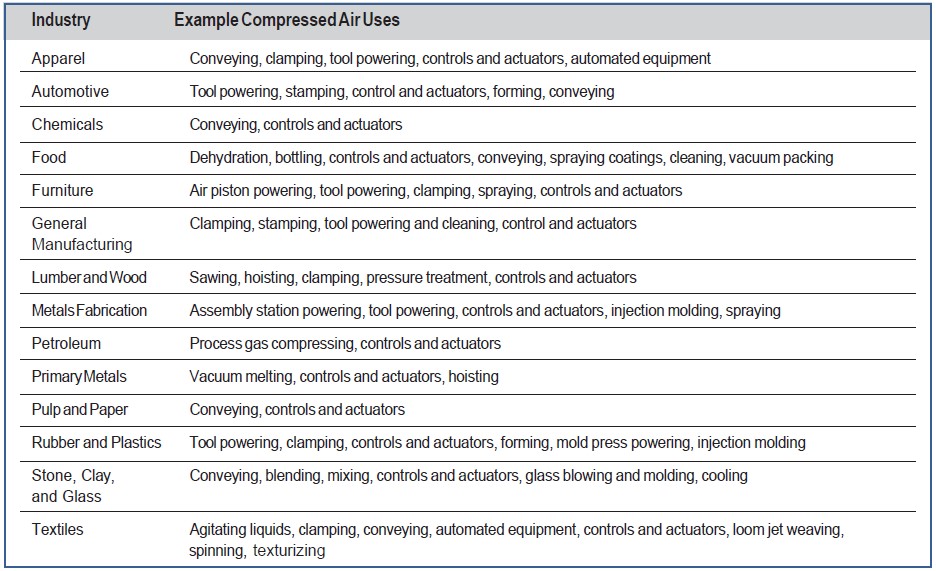
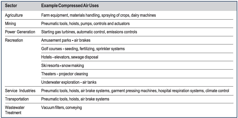
Many manufacturing industries also use compressed air and gas for combustion and process operations such as oxidation, fractionation, cryogenics, refrigeration, filtration, dehydration, and aeration. Table 1.1 lists some major manufacturing industries and the tools, conveying, and process operations requiring compressed air. For some of these applications, however, other sources of power may be more cost effective (see the Tip titled Potentially Inappropriate Uses of Compressed Air in Section 2). Compressed air also plays a vital role in many non-manufacturing sectors, including the transportation, construction, mining, agriculture, recreation, and service industries. Examples of some of these applications are shown in Table 1.2.
The Performance Opportunity
Improving and maintaining peak compressed air system performance requires not only addressing individual components, but also analyzing both the supply and demand sides of the system and how they interact. This practice is often referred to as taking a “systems approach” because the focus is shifted away from components to total system performance.
Applying the systems approach usually involves the following types of interrelated actions:
- Establishing current conditions and operating parameters
- Determining present and future process production needs
- Gathering and analyzing operating data and developing load duty cycles
- Analyzing alternative system designs and improvements
- Determining the most technically and economically sound options, taking into consideration all of the sub-systems
- Implementing those options
- Analyzing operations and energy consumption and analyzing economics (i.e., validating performance)
- Continuing to monitor and optimize the system
- Continuing to operate and maintain the system for peak performance.
Most compressed air systems use considerably more energy than is needed to support the demand. Compressed air systems usually have a wire-to-work efficiency of around 10 percent, which is very low. In many cases, after a thorough review of a compressed air system and after corrective actions are taken, one or more of the compressors may be shut off and the overall system efficiency improved.
System performance improvement opportunities and component efficiency improvement opportunities are addressed in the series of fact sheets that follow.
Performance Tips
The remainder of the Performance Opportunity section of the course is a collection of 12 performance tips that address both component and system issues. Each tip details a specific opportunity for improving compressed air system performance. Topics include:
- Analyzing Compressed Air Needs
- Potentially Inappropriate Uses of Compressed Air
- Compressed Air System Leaks
- Pressure Drop and Controlling System Pressure
- Compressed Air System Controls
- Compressed Air Storage
- Proven Opportunities at the Component Level
- Maintenance of Compressed Air Systems for Peak Performance
- Heat Recovery and Compressed Air Systems
- Baselining Compressed Air Systems
- Compressed Air System Assessments and Audits and Selecting a Service Provider
- Compressed Air System Economics and Selling Projects to Management
The compressed air system diagram shown in Figure 2.1 shows the performance improvement opportunities described in the fact sheets.
1: Analyzing Compressed Air Needs
Compressed air needs are defined by the air quality, quantity, and level of pressure required by the end uses in your plant. Analyzing needs carefully will ensure that a compressed air system is configured properly so that a clean, dry and stable supply of compressed air can be delivered at minimal cost. This analysis should be done in conjunction with the measurements described tip 10: Baselining Compressed Air Systems.
Air Quality
As illustrated in the table, compressed air quality ranges from plant air to breathing air.
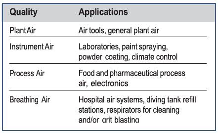
Industrial applications typically use one of the first three air quality levels. Quality is determined by the dryness and contaminant level required by the end uses, and is accomplished with filtering and drying equipment. The higher the quality, the more the air costs to produce. Higher quality air usually requires additional equipment, which not only increases initial capital investment, but also makes the overall system more expensive to operate in terms of energy consumption and maintenance costs.
One of the main factors in determining air quality is whether or not lubricant-free air is required. Lubricant- free air can be produced with either lubricant-free compressors, or with lubricant-injected compressors that have additional separation and filtration equipment. Lubricant-free rotary screw and reciprocating compressors usually have higher first costs, lower efficiency, and higher maintenance costs than lubricant-injected compressors. However, the additional separation and filtration equipment required by lubricant-injected compressors will cause some reduction in efficiency, particularly if systems are not properly maintained. Before selecting a lubricant-free or lubricant-injected compressor, careful consideration should be given to the specific end use for the lubricant- free air, including the risk and cost associated with product contamination.
Air Quantity – Capacity
Required compressed air system capacity for new systems can be determined by summing the requirements of the tools and process operations (taking into account load factors) at the site. For existing system the peak flow can be directly measured using flow meters or estimated by analyzing the response of the compressors in logged data. The total air requirement is not the sum of the maximum requirements for each tool and process, but the sum of the average air consumption of each. High short-term demands should be met by air stored in an air receiver. Systems may need more than one air receiver. Strategically locating air receivers near sources of high demand can also be effective. In most cases, a thorough evaluation of system demand may result in a control strategy that will meet system demand with reduced overall compressor capacity.
Oversized air compressors are extremely inefficient because most compressors use more energy per unit volume of air produced when operating at part-load. In many cases, it makes sense to use multiple, smaller compressors with sequencing controls to allow for efficient operation at times when demand is less than peak.
If a system is properly designed and maintained but is still experiencing capacity problems, an alternative to adding another compressor is to re-examine the use of compressed air for certain applications. For some tasks, blowers or electric tools may be more effective or appropriate. See Tip 2: Potentially Inappropriate Uses of Compressed Air for more information on this system improvement opportunity.
Load Profile
Another key to properly designing and operating a compressed air system is analyzing a plant’s compressed air requirements over time, or load profile. The variation of demand for air over time is a major consideration in system design. Plants with wide variations in air demand need a system that operates efficiently under part-load. Multiple compressors with sequencing controls may provide more economical operation in such a case. Plants with a flatter load profile can use simpler control strategies.
Artificial Demand
Artificial demand is defined as the excess volume of air that is consumed when supplying higher pressure than necessary for applications – unregulated and/or regulated to higher than necessary. Pressure/flow controllers (see Tip 5: Compressed Air System Controls) can help to minimize artificial demand.
Pressure
Different tools and process operations require different pressures. Pneumatic tool manufacturers rate tools at various pressures, and process operation pressure requirements vary widely as specified by the process engineers. Required pressure levels are set to satisfy the highest of all these requirements.
Required pressure levels must take into account system pressure losses from flowing thru dryers, separators, filters, and piping. This forces compressor discharge pressures higher. A rule of thumb for systems in the 100 pounds per square inch gauge (psig) range is: for every 2 pounds per square inch (psi) increase in discharge pressure, energy consumption will increase by approximately 1 percent at full output flow (check performance curves for centrifugal and two-stage, lubricant-injected, rotary screw compressors). There is also another penalty for higher-than-needed pressure. Raising the compressor discharge pressure increases the consumption of every unregulated usage, including leaks, open blowing, etc. Although it varies by plant, unregulated usage is commonly as high as 30 to 50 percent of air demand. For systems in the 100 psig range with 30 to 50 percent unregulated usage, a 2 psi increase in header pressure will increase energy consumption by about another 0.6 to 1.0 percent because of the additional unregulated air being consumed. The combined effect results in a total increase in energy consumption of about 1.6 to 2 percent for every 2 psi increase in discharge pressure for a system in the 100 psig range with 30 to 50 percent unregulated usage.
See the Tip 4: Pressure Drop and Controlling System Pressure for information on ways to reduce system pressure and save energy while maintaining high performance.
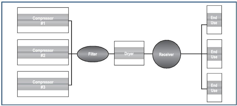
Using Block Diagrams, Pressure Profiles, and Demand Profiles
Two simple tools that are available to help analyze compressed air systems are block diagrams and pressure profiles. Block diagrams identify all the components in the system. A sample diagram is shown in Figure 2.2.
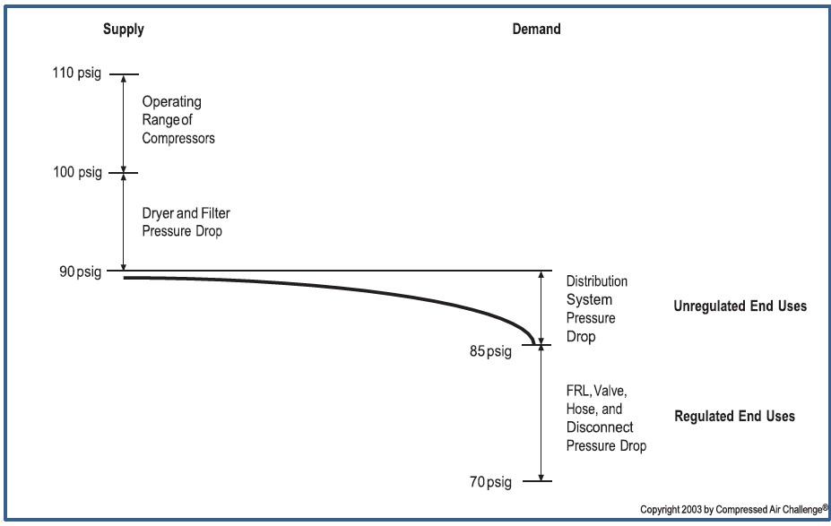
Another way to analyze a compressed air system is to draw a pressure profile. A pressure profile shows the pressure drops through a system. These pressure measurements give feedback for control adjustments, determine pressure drops across components, and help determine system operating pressures. The tools required for measurement are matched, calibrated pressure gauges or differential pressure gauges. The following pressure measurements should be taken:
- Inlet to compressor (to monitor inlet air filter) versus atmospheric pressure
- Differential across air/lubricant separator (if applicable)
- Inter-stage on multi-stage compressors Consider pressure differentials, including:
- Aftercooler
- Treatment equipment (dryers, filters, etc.)
- Various points of the distribution system
- Check pressure differentials against manufacturers’ specifications, if available (high-pressure drops indicate service is required).
Figure 2.3 shows an example of a pressure profile (in a system with excessive pressure drop).
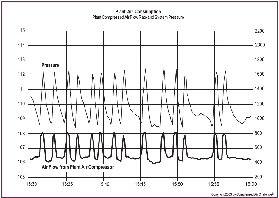
This method gives the pressure profile at a single point in time. Taking data at a single point, or even during various shifts, can provide some answers, but not the complete picture. The use of data loggers is important in determining how a system operates over time. Data logging system pressures and flow can indicate intermittent loads, system disruptions and general system conditions. It can also indicate system changes (e.g. production process changes or air leaks) that can affect the compressed air system operation and efficiency. These variations in pressure and flow can be managed through system control strategies and storage to minimize their impact on production. See Tip 5: Compressed Air System Controls. An example of pressure and demand (airflow) over a period of 30 minutes is shown in Figure 2.4.
2: Potentially Inappropriate Uses of Compressed Air
Compressed air is probably the most expensive form of energy available in a plant. Compressed air is also clean, readily available, and simple to use. As a result, compressed air is often chosen for applications for which other energy sources are more economical. Users should always consider more cost-effective forms of power before considering compressed air.
Many operations can be accomplished more economically using alternative energy sources. Inappropriate uses of compressed air include any application that can be done more effectively or more efficiently by a method other than compressed air. Examples of potentially inappropriate uses of compressed air include:
- Open blowing
- Sparging
- Aspirating
- Atomizing
- Padding
- Dilute-phase transport
- Dense-phase transport
- Vacuum generation
- Personnel cooling
- Open hand-held blowguns or lances
- Diaphragm pumps
- Cabinet cooling
- Vacuum venturis.
- Air motors
Each potentially inappropriate use and a suggested alternative is described below. Engineering assistance may be required for some of the suggestions.
Open Blowing
Open blowing is using compressed air applied with an open, unregulated tube, hose, or pipe for one of these applications:
- Cooling and bearing cooling
- Drying
- Clean-up
- Draining compressed air lines
- Clearing jams on conveyors
The alternatives to open blowing are vast. Some include:
- Brushes
- Brooms
- Dust collection systems
- Zero-air-loss auto drains
- Blowers
- Blowers with knives
- Electric fans
- Electric barrel pumps
- Mixers
- Engineered Nozzles.
Sparging
Sparging is aerating, agitating, oxygenating, or percolating liquid with compressed air. Alternatives to sparging include low-pressure blowers and mixers.
Aspirating
Aspirating is using compressed air to induce the flow of another gas with compressed air such as flue gas. An alternative is a low-pressure blower.
Atomizing
Atomizing is the use of compressed air to disperse or deliver a liquid to a process as an aerosol. An example is atomizing fuel into a boiler. Fluctuating pressure can affect combustion efficiency. An alternative is a low-pressure blower.
Padding
Padding is using compressed air to transport liquids and light solids. Air is dispensed over the material to be moved. The expansion of the air moves the material. The material is usually only moved short distances. An example is unloading tanks or tank cars. Molecular diffusion and wicking are typical problems with padding. An alternative is slow-to-medium pressure blowers.
Dilute-Phase Transport
Dilute-phase transport is used in transporting solids, such as powdery material, in a diluted format with compressed air. Molecular diffusion and wicking are typical problems with dilute phase transport. An alternative is a low- or high-pressure blower or a low- pressure air compressor designed for 35 psig. The pressure required depends upon the moisture content and size of the material being transported.
Dense-Phase Transport
Dense-phase transport is used to transport solids in a batch format. This usually involves weighing a batch in a transport vessel, padding the vessel with compressed air, forcing the batch into a transport line, and moving it in an initial plug with a boost of compressed air at the beginning of the transport pipe. Once the material is moving in a plug, the operation may fluidize the material in a semi-dense or moderate dilute-phase using fluidizers or booster nozzles along the transport path. The material is typically transported to a holding vessel that dispenses it on an as-needed basis using pad air from the secondary transport vessel to move it to the use location. A typical application would be the dense-phase transport of carbon black.
There are typically four compressed air elements to the transport. These elements are control air for the equipment, pad air for the initial transporter, transport air to move it in the piping, and fluidizers or booster nozzles along the transport piping. Most dense-phase manufacturers specify 80 to 90 psig with one single line supporting the entire process. The control air and booster nozzles typically use pressures in the 60 to 70 psig range. The actual pressure required for the pad air and the transport air is typically 30 to 45 psig. Because of the lack of storage in most of these applications and the high-volume, short-cycle transport times, the original equipment manufacturers request 80 to 90 psig and use of the entire supply system as the storage tank. As this usually has a negative impact on the plant air system, separate compressors, filters, and dryers are often applied to this process at the elevated pressure.
Alternatives include supporting the control air, pad air, and boosters with regulated plant air plus metered storage, and using a two-stage, positive displacement blower (28 psig) or single-stage compressor (40 to 50 psig) for the transport air. Another alternative is to use metered storage for both the pad air and transport cycle. This necessitates providing the entire requirement from storage and metered recovery per cycle, with a metering adjustment to refill the vessel just before the next transport cycle. The storage should be sized to displace the required air first for the pad and then for the transport cycles within an allowable pressure drop to terminate the transport cycle pressure at the required pressure. This will flatten the volumetric load on the system, eliminate any impact on other users, and reduce the peak energy required to support the process.
Vacuum Generation
The term vacuum generation describes applications where compressed air is used in conjunction with a venturi, eductor, or ejector to generate a negative- pressure mass flow. Typical applications are hold-downs or 55-gallon, drum-mounted, compressed air vacuum cleaners. This is an inefficient application although for very intermittent use (less than 30 percent load factor), compressed air can be a reasonable solution. An alternative is a vacuum pump. If a compressed-air-generated vacuum is required, install a solenoid valve on the compressed air supply line to shut this application off when it is not needed.
Vacuum generators are used throughout industry. Some applications for vacuum generators include:
- Shop vacuums
- Drum pumps
- Palletizers
- De-palletizers
- Box makers
- Packaging equipment
- Automatic die-cutting equipment.
Vacuum generators are selected for safety, ease of installation, physical size of the generator, the fact that no electricity is required at the point-of-use, and low first cost. Vacuum generators are usually less economical to operate than central vacuum systems.
As a rule, in a base load situation, if the vacuum generator is operating less than 30 percent of the time, it will be more economical to operate than a central vacuum system. Otherwise, vacuum generators are, in general, less effective at pulling a vacuum and cost as much as five times more to operate than a dedicated vacuum pump. Using vacuum generators for shop vacuums and drum pumps, which are typically peak load applications, could cause another compressor to turn on and stay on until it times out. Having to operate a second compressor because of the added demand associated with vacuum generators eliminates any apparent savings even if operated only once a day for a short period of time.
A dedicated vacuum pump or the use of central vacuum system will provide more suction force at a fraction of the cost of vacuum produced by compressed air. In this case, it is significantly more cost effective to provide a system that is designed into the machine from the beginning than to retrofit a piece of equipment. This can be accomplished by being proactive at the time the machine specifications are prepared and the purchase orders issued. Vacuum generators must be applied properly and only after taking life cycle costs into consideration.
Vacuum venturis are a common form for vacuum generation with compressed air systems. In a venturi system, compressed air is forced through a conical nozzle. Its velocity increases and a decrease in pressure occurs. This principle, discovered by 18th century physicist G. B. Venturi, can be used to generate vacuum without a single moving part.
Multi-stage venturi devices generally provide a more efficient ratio of vacuum flow to compressed air consumed than single-stage venturi devices. Where vacuum requirements vary significantly, or are cyclical with a duty cycle of less than 30 percent, multi-stage, venturi-type vacuum generators with pressure regulators and automatic shut-off controls on the compressed air supply may be more efficient than continuously operating mechanical-vacuum pump systems. These devices also can be equipped with a vacuum switch that signals a solenoid valve to shut off the air supply when a set vacuum level is attained, thus reducing air consumption in non-porous applications. They may also be suitable where it is impractical to have a central vacuum system, particularly where the uses may not be confined to one area.
Personnel Cooling
Personnel cooling is when operators direct compressed air onto themselves for ventilation. This is dangerous because it can shoot particulates into the skin. A 1/4-inch tube continually blowing air on an operator can consume 15 to 25 horsepower of compressed air. An alternative is fractional horsepower fans of 1/4 hp or less.
Open Hand-Held Blowguns or Lances
Unregulated hand-held blowing is not only a violation of most health and safety codes, but is also very dangerous. Hand-held blowguns that conform to all occupational health and safety standards should be used.
There are different styles of blowguns that can deliver various airflows, velocities, and concentrations. The proper gun must be selected for each application. Care must be taken to ensure optimized nozzles that consume more than the original nozzles are not inadvertently selected. Pipes installed in the end of hose and unregulated non-approved guns must not be used. Blowguns must have no more than 30 psig discharge nozzle pressure. The nozzle should be constructed to relieve backpressure if the nozzle is plugged or blocked. The blowgun must also have a spring-operated throttle mechanism so it shuts off automatically if it is dropped.
Diaphragm Pumps
A common error is to not size diaphragm pumps for the maximum viscosity, highest pressure, and highest volume required. The result is poor performance and an increased supply pressure requirement.
Diaphragm pumps are commonly found installed without regulators and speed control valves. Those diaphragm pumps that are installed with regulators are found with the regulators adjusted higher than necessary. This is often because of undersized regulators and supply piping or hose. The higher-than-necessary setting of the regulator increases the demand on the compressed air system and increases operating costs.
With a higher pressure setting, the amount of compressed air admitted into the diaphragm chamber is increased above that which is actually required to move the product. The amount of product actually transferred remains the same, but the amount of air used increases with the increased pressure.
The regulator should be adjusted to equal the maximum head that the pump is required to provide. A flow control valve installed up stream of the regulator will accomplish the required speed control. Operating the diaphragm pump without speed control increases the rate of compressed air consumption by increasing the strokes per minute of the diaphragm pump. The speed control should be adjusted to pump product in the maximum allowable time. As a general rule, the regulator and flow control valve are not included with the standard pump package. Also, when the pump has no liquid or slurry to pump, it will rapid cycle, wearing out the diaphragm and wasting air. The pump controls must be configured to turn the pump off when there is nothing to pump.
Cabinet Cooling
Cabinet cooling should not be confused with panel purging. The following are typical applications where cabinet cooling is found.
- Programmable controllers
- Line control cabinets
- Motor control centers
- Relay panels
- Numerical control systems
- Modular control centers
- Computer cabinets.
When first cost is the driving factor, open tubes, air bars (copper tube with holes drilled long the length of the tube) and vortex tube coolers are often used to cool cabinets. When life-cycle costs are taken into consideration, these choices prove to be expensive. It is not uncommon to find an open tube or air bar consuming 7-1/2 horsepower (hp) of compressed air to cool a cabinet. Vortex tube coolers can be an improvement over open tubes and air bars because they are often cycled with a thermostat control, which reduces air consumption. However, air to air, air to water and refrigerated cabinet coolers are available that only use 1/3 hp to accomplish the same task.
Air Motors
Compressed air driven vane or piston motors are used in a wide variety of tools and equipment, often used where light weight, or sparkless explosion proof operation is required. Since it requires a minimum of 7 to 8 hp of equivalent compressor power for each hp of air motor shaft output it is worthwhile to consider converting applications that do not require special treatment to direct drive electric source.
Other Potentially Inappropriate Uses
Other improper uses of compressed air are unregulated end uses and those that supply air to abandoned equipment, both of which are described below.
Unregulated End Uses
A pressure regulator is used to limit maximum end- use pressure and is placed in the distribution system just prior to the end use. If an end use operates without a regulator, it uses full- system pressure. This results in increased system air demand and energy use, since the end use is using air at this higher pressure. High pressure levels can also increase equipment wear, resulting in higher maintenance costs and shorter end use equipment life.
Abandoned Equipment
Many plants undergo numerous equipment configuration changes over time. In some cases, plant equipment is no longer used. Air flow to this unused equipment should be stopped, preferably as far back in the distribution system as possible without affecting operating equipment.
Using Compressed Air
As a general rule, compressed air should only be used if safety enhancements, significant productivity gains, or labor reductions will result. Typical overall efficiency is 10 to 15 percent. If compressed air is used for an application, the amount of air used should be the minimum necessary quantity and pressure and should be used for the shortest possible duration. Compressed air use should also be constantly monitored and re-evaluated.
3: Compressed Air System Leaks
Leaks can be a significant source of wasted energy in an industrial compressed air system, sometimes wasting 20 to 30 percent of a compressor’s output. A typical plant that has not been well maintained will likely have a leak rate equal to 20 percent of total com- pressed air production capacity. On the other hand, proactive leak detection and repair can reduce leaks to less than 5 to 10 percent of compressor output.
In addition to being a source of wasted energy, leaks can also contribute to other operating losses. Leaks cause a drop in system pressure, which can make air tools function less efficiently, adversely affecting production. In addition, by forcing the equipment to run longer, leaks shorten the life of almost all system equipment (including the compressor package itself). Increased running time can also lead to additional maintenance requirements and increased unscheduled downtime. Finally, leaks can lead to adding unnecessary compressor capacity.
While leakage can come from any part of the system, the most common problem areas are:
- Couplings, hoses, tubes, and fittings
- Pressure regulators
- Open condensate traps and shut-off valves
- Pipe joints, disconnects, and thread sealants
Estimating Amount of Leakage
For compressors that have start/stop or load/unload controls, there is an easy way to estimate the amount of leakage in the system. This method involves starting the compressor when there are no demands on the system (when all the air-operated, end-use equipment is turned off). A number of measurements are taken to determine the average time it takes to load and unload the compressor. The compressor will load and unload because the air leaks will cause the compressor to cycle on and off as the pressure drops from air escaping through the leaks. Total leakage (percentage) can be calculated as follows:

Leakage will be expressed in terms of the percentage of compressor capacity lost. The percentage lost to leakage should be less than 5 to 10 percent in a well- maintained system. Poorly maintained systems can have losses as high as 20 to 30 percent of air capacity and power. Note that this method may not account for idle end use equipment where the compressed air has been turned off.
Leakage can be estimated in systems with other control strategies if there is a pressure gauge installed on or after the air receiver. This method requires an estimate of total system volume, including any downstream secondary air receivers, air mains, and piping (V, in cubic feet). The system is started and brought to the normal operating pressure (P1). Measurements should then be taken of the time (T) it takes for the system to drop to a lower pressure (P2), which should be a point equal to about one-half the operating pressure.
Total leakage of free air can be calculated as follows:
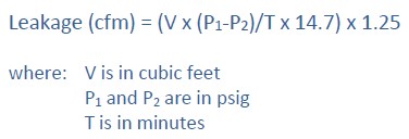
The 1.25 multiplier corrects leakage to normal system pressure, allowing for reduced leakage with falling system pressure. Again, leakage of greater than 10 percent indicates that the system can likely be improved. These tests should be carried out on a regular basis as part of a leak detection and repair program.
Leak Detection
Since air leaks are almost impossible to see, other methods must be used to locate them. The best way to detect leaks is to use an ultrasonic acoustic detector, which can recognize the high-frequency hissing sounds associated with air leaks. These portable units consist of directional microphones, amplifiers, and audio filters, and usually have either visual indicators or ear- phones to detect leaks. A simpler method is to apply soapy water with a paint brush to suspect areas. Although reliable, this method can be time consuming.
Ultrasonic Leak Detection
Ultrasonic leak detection is probably the most versatile form of leak detection. Because of its capabilities, it is readily adapted to a variety of leak detection situations. The principle behind ultrasonic leak detection is simple. In a pressure or vacuum leak, the leak flows from a high-pressure laminar flow to a low-pressure turbulence. The turbulence generates a white noise, which contains a broad spectrum of sound ranging from audible to inaudible frequencies. An ultrasonic sensor focuses in on the ultrasonic elements in the noise. Because ultrasound is a short wave signal, the sound level will be loudest at the leak site. Ultrasonic detectors are generally unaffected by back- ground noises in the audible range because these signals are filtered out.
Ultrasonic detectors can find mid- to large-sized leaks. The advantages of ultrasonic leak detection include versatility, speed, ease of use, the ability to perform tests while equipment is running, and the ability to find a wide variety of leaks. They require a minimum of training, and operators often become competent after 15 minutes of training.
Because of its nature, ultrasound is directional in transmission. For this reason, the signal is loudest at its source. By generally scanning around a test area, it is possible to very quickly hone it on a leak site and pin point its location. For this reason, ultrasonic leak detection is not only fast, it is also very accurate.
How to Fix Leaks
Leaks occur most often at end-use joints and connections. Stopping leaks can be as simple as tightening a connection or as complex as replacing faulty equipment, such as couplings, fittings, pipe sections, hoses, joints, drains, and traps. In many cases, leaks are caused by failing to clean the threads or by bad or improperly applied thread sealant. Select high quality fittings, disconnects, hose, tubing, and install them properly with appropriate thread sealant.
Non-operating equipment can be an additional source of leaks. Equipment no longer in use should be isolated with a valve in the distribution system.
Another way to reduce leaks is to lower the air pressure of the system. The lower the pressure differential across an orifice or leak, the lower the rate of flow, so reduced system pressure will result in reduced leakage rates. Stabilizing the system header pressure at its lowest practical range will minimize the leakage rate for the system. Once leaks have been repaired, the compressor control system must be re-evaluated to realize the total savings potential.
Establishing a Leak Prevention Program
There are two basic types of leak repair programs, the leak tag program and the seek and repair program. The seek and repair program is the simplest. As it states, you simply find the leak and repair it immediately. With the leak tag program, the leak is identified with a tag and logged for repair at a later time. This is often a two-part tag; one part stays on the leak and the other part is turned into the maintenance department, identifying the location, size, and description of the leak to be repaired. The best approach depends on the type, size, and the culture/work practices of the facility. It is more likely that the best solution will be a combination of the two. In any case, there are several key elements for a successful leak program.
- Baseline compressed air usage. Establish good grounds for comparison on the effectiveness of the compressed air leak repair program. (See Tip 10: Baselining Compressed Air Systems.)
- Establish leak loss. See the section on estimating leak loss in this Tip.
- Determine cost of air leaks. The cost of compressed air leaks is one of the most important aspects of the program. It should be used as a baseline, not only for the effectiveness and promotion of the program, but also to illustrate the amount of resources that can cost effectively be allocated to the program.
- Identify leaks. Survey the facility and identify the leaks. Leaks can be identified by many methods. The most common is using an ultrasonic acoustic leak detector. There are many types and price ranges, but for most applications, the inexpensive hand- held meter will identify leaks and give an indication of the size or intensity.
- Document the leaks. Document the location, type, size, and the estimated cost of the leak. Any documentation should be compatible with the facility’s predictive maintenance program. Leak tags can also be used but should not take the place of a master leak list. If you are using the seek and repair method, leaks should still be documented so the number and effectiveness of the program can be tracked.
- Prioritize leak repair. Fix the biggest leaks first to get the biggest savings. This will ensure a good start to the air leak program.
- Adjust controls. Once the leaks are fixed, adjust the compressor controls.
- Document repairs. Showing the fixed leaks and the cost savings shows the effectiveness of the program and strengthens support for it. Documenting the repairs and the type of leaks can also indicate equipment that is a recurring problem. When this occurs, look at the process for a root cause and develop a permanent solution to stop the recurring air leak.
- Compare baselines and publish results. By comparing before and after results, the effectiveness of the program and the savings can be determined. Then, tell “the world” about the program and the results that have been achieved.
This is very important because showing the savings will solidify support for the program. - Start over again. Air leaks continue to occur, so the program must be ongoing. Periodic reviews should be done on the system, and the process repeated as necessary to maintain system efficiency.
A good compressed air system leak repair program is very important to maintaining the efficiency, reliability, stability, and cost effectiveness of any compressed air system.
4: Pressure Drop and Controlling System Pressure
Pressure drop is a term used to characterize the reduction in air pressure from the compressor discharge to the actual point-of-use. Pressure drop occurs in the piping as the compressed air travels through the treatment and distribution system. A properly designed system should have a pressure loss of much less than 10 percent of the compressor’s discharge pressure, measured from compressor discharge output to the end point-of-use.
Excessive pressure drop will result in poor system performance and excessive energy consumption. Pressure drop upstream of the compressor signal requires higher compression pressures to achieve the control settings on the compressor. Control specialists should be consulted for these applications. Flow restrictions of any type require higher operating pressures than necessary, and minimizing differentials in all parts of the system is an important part of efficient operation. The most typical problem areas include the aftercooler, lubricant separators, air treatment equipment, and check valves. A rule of thumb for systems in the 100 psig range is: for every 2 psi increase in discharge pressure, energy consumption will increase by approximately 1 percent at full output flow (check performance curves for centrifugal and two-stage, lubricant-injected, rotary screw compressors).
There is an additional penalty for higher-than-needed pressure. Elevated system pressure increases unregulated uses, such as leaks, open blowing, and production applications. The added demand at elevated pressure is termed “artificial demand” and can substantially increase energy consumption. Although it varies by plant, unregulated usage is commonly as high as 30 to 50 percent of air demand. For systems in the 100 psig range a 2 psi increase in header pressure will increase energy consumption another 0.6 to 1.0 percent because of the additional unregulated air being consumed. The combined effect results in a total increase in energy consumption of about 1.6 to 2 percent for every 2 psi increase in discharge pressure.
Pressure drop in the distribution system and in hoses and flexible connections at points-of-use results in lower operating pressure to the user. If the point-of- use operating pressure has to be increased, try reducing the pressure drops by properly sizing components or adding secondary storage in the system before adding capacity or increasing the system pressure. Increasing the compressor discharge pressure or adding compressor capacity may result in significant increases in energy consumption and should be the last resort.
What Causes Pressure Drop?
Any type of obstruction, restriction, or roughness in the system will cause resistance to air flow and cause pressure drop. In the distribution system, the highest pressure drops usually are found at the points- of-use, including undersized or leaking hoses, tubes, disconnects, filters, regulators and lubricators (FRLs) usually within the last 30 feet of the system. On the supply side of the system, air/lubricant separators, aftercoolers, moisture separators, dryers and filters can be the main items causing significant pressure drops.
The maximum pressure drop from the supply side to the points-of-use will occur when the compressed air flow rate is highest. System components should be selected based upon these conditions and the manufacturer of each component should be requested to supply pressure drop information under these conditions. Filter elements should be changed when the pressure drop approaches the maximum recommended by the manufacturer. In many cases the element change is dictated by energy losses.
The distribution piping system is often diagnosed as having excess pressure drop because a point-of-use component cannot sustain the required down- stream pressure. If a regulator is set at 85 psig and an upstream filter has a pressure drop of 20 psi, the system upstream of the filter and regulator would have to maintain at least 105 psig. The 20 psi pressure drop may be blamed on the system piping rather than on the components at fault. The correct diagnosis requires pressure measurements at different points in the system to identify the component(s) causing the excess pressure drop. In this case the filter element or filter should be replaced, not the piping.
Minimizing Pressure Drop
Minimizing pressure drop requires a systems approach in design and maintenance of the system. Air treatment components, such as aftercoolers, moisture separators, dryers, and filters, should be selected with the lowest possible pressure drop at specified maximum operating conditions. When installed, the recommended maintenance procedures should be followed and documented. Additional ways to minimize pressure drop are as follows:
- Properly design the distribution system. Size main lines for maximum flow with a 1-2%maximum pressure drop and be sure to allow for system growth.
- Operate and maintain air treatment equipment to reduce the effects of moisture, such as pipe corrosion.
- Consider pressure drop when selecting air treatment equipment. Install ∆P gauges across dryers and filters and pressure gauges at various points in the distribution system.
- Specify pressure regulators, lubricators, hoses, and connections having the best performance characteristics at the lowest pressure differential. These components must be sized based upon the actual rate of flow and not the average rate of flow. End use equipment should be specified and operated at the lowest efficient operating pressures.
Controlling System Pressure
Many plant air compressors operate with a full- load discharge pressure of 100 psig and an unload discharge pressure of 110 psig or higher. Many types of machinery and tools can operate efficiently with an air supply at the point-of-use of 80 psig or lower. If the air compressor discharge pressure can be reduced, significant savings can be achieved. Check with the compressor manufacturer for performance specifications at different discharge pressures.
An air compressor capacity control pressure signal is normally located at the discharge of the compressor package. In some systems it is possible to move the pressure signal location downstream of the compressed air dryers and filters to achieve a common signal pressure for all the compressors in the system. Some dangers must be recognized and precautionary measures taken. The control range pressure setting must be reduced to allow for actual and potentially increasing pressure drop across the dryers and filters. It is important to provide controls that prevent exceeding the maximum allowable compressor discharge pressure and drive motor amps of each compressor in the system.
Reducing system pressure also can have a cascading effect in improving overall system performance, reducing leakage rates, and helping with capacity and other problems. Reduced pressure also reduces stress on components and operating equipment. However, a reduced system operating pressure may require modifications to other components, including pressure regulators, filters, hoses, and the size and location of compressed air storage.
Lowering average system pressure requires caution because large changes in demand can cause the pressure at points-of-use to fall below minimum requirements, which can cause equipment to function improperly. These problems can be avoided with careful matching of system components, controls, and compressed air storage capacity and location. Pressure/flow controllers can also be used to control system pressure. (See Tip 5: Compressed Air System Controls.)
If an individual application requires higher pressure, it may be best to replace or modify this application, instead of raising the operating pressure of the whole system. It may be possible to have a larger diameter cylinder, gear ratios may be changed, mechanical advantage may be improved, or a larger air motor may be used. The cost of improvements probably will be insignificant compared to the energy reduction achieved from operating the system at the lower pressure.
It is also important to check if manufacturers are including pressure drops in filters, pressure regulators, and hoses in their pressure requirements for end-use equipment, or if the pressure requirements as stated are after those components. A typical pressure differential for a filter, pressure regulator, and hose is 7 pounds per square inch differential (psid), but it could be much higher in poorly designed and maintained systems.
When demand pressure has been successfully reduced and controlled, attention then should be turned to the compressor control set points to obtain more efficient operation, and also to possible unloading or shutting off a compressor to further reduce energy consumption.
5: Compressed Air System Controls
Compressed air system controls regulate system pressure by matching the compressed air supply with system demand, and they are one of the most important determinants of overall system energy efficiency. Good control translates compressed air savings due to efficiency measures into proportionally lower input power. This Tip discusses both individual compressor control and overall system control of plants with multiple compressors. Proper control is essential to efficient system operation and high performance. The objective of any control strategy is also to shut off unneeded compressors or delay bringing on additional compressors until needed.
Compressor systems are typically comprised of multiple compressors delivering air to a common plant air header. The combined capacity of these machines is generally sized to meet the maximum plant air demand. System controls are almost always needed to orchestrate a reduction in the output of the individual compressor(s) during times of lower demand. Compressed air systems are usually designed to operate within a fixed pressure range and to deliver a volume of air that varies with system demand. System pressure is monitored and the control system decreases compressor output when the pressure reaches a predetermined level. Compressor output is then increased again when the pressure drops to a lower predetermined level.
The difference between these two pressure levels is called the control range. Depending on air system demand, the control range can be anywhere from 2 to 20 psi. In the past, individual compressor controls and non-supervised multiple machine systems were slow and imprecise. This resulted in wide control ranges and large pressure swings. As a result of these large swings, individual compressor pressure control set points were established to maintain pressures higher than needed. This ensured that swings would not go below the minimum requirements for the system.
Today, faster and more accurate microprocessor-based system controls and variable speed compressors with tighter control ranges allow for a drop in the system pressure set points. Precise control systems are able to maintain lower average pressure without going below minimum system requirements.
A rule of thumb for systems in the 100 psig range is: for every 2 psi decrease in discharge pressure, energy consumption will decrease by approximately 1 percent at full output flow (check performance curves for centrifugal and two-stage, lubricant-injected, rotary screw compressors). There is also another benefit of lowering pressure. Reducing the compressor discharge pressure decreases the demand of every unregulated usage, including leaks, open blowing, etc. Although it varies by plant, unregulated usage is commonly as high as 30 to 50 percent of air demand. For systems in the 100 psig range with 30 to 50 percent unregulated usage, a 2 psi decrease in header pressure will decrease energy consumption by about another 0.6 to 1.0 percent because of the lower unregulated air being consumed. The combined effect results in a total decrease in energy consumption of about 1 to 1.6 percent for every 2 psi decrease in discharge pressure for a system in the 100 psig range with 30 to 50 percent unregulated usage.
Caution must be taken when lowering average system header pressure, because large, sudden changes in demand can cause the pressure to drop below minimum requirements, which can lead to improper functioning of equipment. With careful matching of system controls and storage capacity, these problems can be avoided.
Controls and System Performance
Few air systems operate at full-load all of the time. Part-load performance is therefore critical, and is primarily influenced by compressor type and control strategy. The type of control specified for a given system is largely determined by the type of compressor being used and the facility’s demand profile. If a system has a single compressor with a very steady demand, a simple control system may be appropriate. On the other hand, a complex system with multiple compressors, varying demand, and many types of end uses will require a more sophisticated strategy. In any case, careful consideration should be given to both compressor and system control selection because they can be the most important factors affecting system performance and efficiency.
Individual Compressor Control Strategies
Over the years, compressor manufacturers have developed a number of different types of control strategies. Controls, such as start/stop and load/unload, respond to reductions in air demand, by monitoring increasing compressor discharge pressure and turning the compressor off or unloading it at a set unload point so that it does not deliver air for periods of time. Modulation, variable displacement, multi-step, and variable speed controls allow the compressor to operate at part-load and deliver a reduced amount of air during periods of reduced demand. Some compressors have more than one control mode and the manual selection of the mode is an operator function. The efficiency of these control modes varies widely depending on site conditions, so careful selection should be made to maintain good overall efficiency.
Start/Stop. Start/stop is the simplest control available and can be applied to either reciprocating or rotary screw compressors. The motor driving the compressor is turned on or off in response to the discharge pressure of the machine. Typically, a simple pressure switch provides the motor start/stop signal. This type of control should not be used in an application that has frequent cycling, because repeated starts will cause the motor to overheat and other compressor components to require more frequent maintenance. This control scheme is typically only used for applications with very low-duty cycles for compressors in the 30 horsepower (hp) and under range. Its advantage is that power is used only while the compressor is running, making it quite efficient, but this is offset by having to compress to a higher receiver pressure to allow air to be drawn from the receiver while the compressor is stopped. Some modern controls will allow larger compressors to start and stop, saving energy, if the control detects that the maximum motor starts will not be exceeded.
Load/Unload. Load/unload control, also known as online/offline control, allows the motor to run continuously, but unloads the compressor when the discharge pressure is adequate. Compressor manufacturers use different strategies for unloading a compressor, but in most cases, an unloaded rotary screw compressor will consume 15 to 35 percent of full-load horsepower while delivering no useful work. As a result, some load/unload control schemes can be inefficient. For lubricated screw compressors, the effective size of the system storage affects part load efficiency. Compressors with limited effective storage can experience short cycling, which will have an even greater negative effect on efficiency and reliability.
Most single acting reciprocating compressors pressure controls are designed as two-step, either start/stop or load/unload. Larger double acting reciprocating compressors can be two-step, three-step cylinder unloading (0, 50, 100 percent) or five-step (0, 25, 50, 75, 100 percent) control. These control schemes generally exhibit an almost direct relationship between motor power consumption and loaded capacity.
Modulating Controls. Modulating (throttling) inlet control allows the output of a compressor to be varied to meet flow requirements. Throttling is usually accomplished by partially closing the inlet valve, thereby restricting inlet air to the compressor. This control scheme is applied to centrifugal and lubricant-injected rotary screw compressors. This control method cannot be used on reciprocating or lubricant-free rotary screw compressor and when applied to lubricant-injected rotary screw compressors, is an inefficient means of varying compressor output at the lower demand levels.
When used on centrifugal compressors, more efficient results are obtained, particularly with the use of inlet guide vanes, which direct the air in the same direction as the impeller inlet. However, the amount of capacity reduction is limited by the potential for surge and minimum throttling capacity, which is in the basic design parameters of each specific unit.
Inlet-valve modulation used on lubricant-injected rotary air compressors allows compressor capacity to be adjusted to match demand. A regulating valve senses system or discharge pressure over a prescribed range (usually about 10 psi) and sends a proportional pressure to operate the inlet valve. Closing (or throttling) the inlet valve causes a pressure drop across it, reducing the inlet pressure at the compressor and, hence, the mass flow of air. Since the pressure at the compressor inlet is reduced while discharge pressure is rising, the compression ratios are increased so that energy savings are somewhat limited.
Inlet valve modulation is normally limited to a range of from 100 percent to about 40 percent of rated capacity. When operating at 40 percent rated capacity and when discharge pressure reaches full load pressure plus 10 psi, it is assumed demand is insufficient to require continued air discharge to the system. At this point the compressor will operate fully unloaded, like a compressor using load/unload controls.
Dual-Control/Auto-Dual. For lubricant-injected rotary screw compressors, auto-dual control provides the addition of an overrun timer to stop the compressor after running unloaded for a pre-set time, thereby saving power.
Variable Displacement. Allows progressive reduction of the compressor displacement without reducing the inlet pressure. Manufacturers use turn valve, slide valve, spiral valve or poppet valves to control the compressor discharge pressure and reduce energy consumption at part load.
Some lubricant-injected rotary screw compressors can vary their compression volumes (ratio) through the first 50% of available capacity using turn valves, spiral valves or poppet valves. These are generally applied in conjunction with modulating inlet valves to provide more accurate pressure control with improved part-load efficiency. This control scheme reduces the power and flow in a very similar manner as the reciprocating pocket valves, by keeping the compression ratios stable, which keeps the power consumption near optimal levels. For capacities below 50 percent, the compressor will typically operate in load/unload or modulation mode.
There are sometimes separate manual control adjustments for the modulation valve, the variable displacement valve and the load/unload pressures. Each adjustment must be carefully coordinated with the other in order to benefit from this type of control. Adjustment of these settings should be done using trained personnel.
Variable Speed Drives. Variable speed is an efficient means of rotary compressor capacity control, using integrated variable frequency AC or switched reluctance and other DC drives. Compressor discharge pressure can be held to within 1or 2 psi over a wide range of capacity, allowing additional system energy savings.
Some variable speed compressors also use variable displacement controls to enhance the machine turn-down range.
Compressors equipped with variable speed drive controls continuously adjust the drive motor speed within a variable range to match variable demand requirements with an almost direct one to one relationship to full load power consumption. At or near full-output capacity, a variable speed drive compressor will use more input power than a comparable fixed speed unit due to the inherent drive losses. Also, at low speeds the package efficiency of variable speed compressors falls off. Therefore, continuous operation at full or minimum speeds should be avoided. Best efficiency occurs if the variable speed compressor operates between 30 and 80 percent speed for the majority of its operating hours.
Variable speed compressors typically load/unload or start/stop at output capacities below minimum speed. Long term operation of lubricated screw compressors at below minimum speed should be avoided to prevent condensate contamination of the compressor lubricant. Variable speed compressors require proper effective storage to avoid continuously ramping the speed up and down which may damage the driver.
Capacity Controls for Centrifugal Type Compressors. Centrifugal compressors have complex characteristics affected by inlet air density and inter-stage cooling water temperature.
Two potential occurrences must be avoided. The first is surge, caused by a flow reversal, which can occur at low flow rates and can cause damage to the compressor. Surge is avoided by limiting the amount of flow reduction generally controlled by preset minimum motor ampere limiters. The second is choke at increased flow rates below design pressure, when the velocity of the air at the impeller inlet approaches the speed of sound and flow and head cannot be sustained.
The flow rate can be reduced by an inlet throttle valve, which reduces the pressure at the inlet to the first-stage impeller. This “constant pressure control” reduces the mass flow in direct proportion to the absolute inlet pressure. The inlet air density also is reduced, resulting in reduced pressure head produced by the impeller.
A variation of this uses inlet guide vanes, which also reduce the mass flow and the inlet air density, but cause the air to be directed radially towards the impeller inlet in the same direction as the impeller rotation. This improves the efficiency compared with simple throttling. In some cases, discharge bypass or blow-off control is used to limit flow delivered to the compressed air system. “Capacity can typically be reduced from 100 percent capacity to about 70-80 percent with reasonable energy reduction” At lower capacities compressed air is discharged to the atmosphere (“blowoff”) through a discharge silencer or cooled and returned to the compressor inlet. This is a waste of energy and should be used only where necessary to avoid surge.
Multiple Compressor Control
Systems with multiple compressors can be set up manually or use more sophisticated controls to orchestrate efficient compressor operation and constant air pressure delivery to the system. Network controls use the on-board compressor controls’ microprocessors linked together to form a chain of communication that makes decisions to stop/start, load/unload, modulate, vary displacement, and vary speed. Usually, one compressor assumes the lead with the others being subordinate to the commands from this compressor.
System master controls coordinate all of the functions necessary to optimize compressed air as a utility. System master controls have many functional capabilities, including the ability to monitor and control all components in the system, as well as trending data to enhance maintenance functions and minimize costs of operation. Other system controllers, such as pressure/flow controllers, can also substantially improve the performance of some systems.
The objective of an effective automatic system control strategy is to match system demand with compressors operated at or near their maximum efficiency levels. This can be accomplished in a number of ways, depending on fluctuations in demand, available storage receiver capacity, and the characteristics of the equipment supplying and treating the compressed air.
Local Control. Systems within multiple compressors can be manually operated by coordinating the load and unload pressure settings of each individual compressor in a cascaded arrangement (provide graphic). This method needs to be carefully planned to compensate for pressure differentials across dryers and filters and to ensure pressures do not exceed the rated capacity of any system compressors. Special considerations may exist if one or more of the system compressors use variable speed control to avoid a condition called
“control gap”. This can also be avoided with some system controllers.
Network Controls. Less sophisticated network controls use the cascade set point scheme to operate the system as a whole. Those systems are capable of avoiding part load compressors, but can still present the problem of approaching production’s minimum pressure requirement as more and more compressors are added and the range of compressor load and unload set points increases.
Some network control systems use single set-point logic to make their operational decisions to start/stop, etc. Use of a single set-point system should include a control specialist. The intent is to save energy by keeping compressor discharge pressures as low as possible. In systems with positive- displacement compressors (reciprocating, rotary screws, etc.) the best system efficiency occurs when all compressors are kept fully loaded except for one trim compressor that is operated in some part-load fashion specific to the design of the machine. The trim compressor is typically a unit with the best part load efficiency such as a variable speed compressor or a unit with low unloaded power consumption.
Three major disadvantages of network system controls are:
- They are capable of controlling only air compressors.
- They cannot easily be networked with remote compressor rooms.
- Typically they only work with compressors of the same brand and configuration because of micro-processor compatibility issues.
Expensive upgrades or retrofits may be required to make different brands of compressors, or older versions of the same brand, work in the system. In some cases, retrofits are not available and a different brand or outdated compressors cannot be used in the control scheme.
There are no network controls available that can coordinate the control of rotary screw, reciprocating, and centrifugal compressors as one system. To do this, system master controls are required, particularly if there is a desire to monitor and operate compressors, cooling systems, dryers, filters, automatic drain traps, storage, pressure/ flow controllers, and any other part of a compressed air system that a facility might want included in the control scheme.
System Master Controls. If complexity outpaces the capabilities of local and network controls, a system master control is required to coordinate all of the functions necessary to optimize compressed air as a utility. System master controls have many functional capabilities, including the ability to monitor and control all components in the system, as well as to trend data and provide performance reports to enhance maintenance functions and help system operators minimize costs of operation. System master controls interface with all brands and types of air compressors, and can coordinate the operation of satellite compressor rooms spread around the facility, or in different buildings across an industrial campus. The primary function of these controls, as with the network controls, is to operate a multiple compressor system in harmony.
The least sophisticated have few, if any, of the features mentioned above and use cascading set-point logic to control compressors. The most sophisticated, state-of-the-art system master controls use rate-of-change dynamic analysis to make decisions regarding how the compressed air system responds to changes. These changes can occur on the demand side, supply side, or in the ambient conditions. All affect the performance of the system and have a role in how the system should respond. Some of these require short duration support, such as additional storage. Others require additional compressor power to be brought online, and some will require a combination of both.
A properly configured system master control can determine the best and most energy-efficient response to events that occur in a system. The number of components a system master control can interface with is governed by practicality and cost limitations. System master control layout has the capability of performing many other complex functions, such as effective monitoring and reporting of key performance indicators so proactive actions can be initiated to maintain system efficiency and reliability.
Multiple Compressor Control with VSD
If one or more variable speed compressors operate with multiple fixed speed compressors some special considerations apply. In this case the control strategy should be arranged so that the variable speed compressor is always the trim compressor, regardless of how many fixed speed compressors are running.
Integration of variable compressors in systems with multiple compressors should be done in consultation with the manufacturer or a compressed air system expert. Care should be taken in sizing variable speed compressors as some models may have limited ranges.
Pressure/Flow Controllers
Pressure/flow controllers are precision pilot-operated system pressure regulators used in conjunction with the individual compressor or system controls described previously. A pressure/flow controller does not directly control a compressor and is generally not included as part of a compressor package. This is a device that serves to separate the supply side of a compressor system from the demand side. This requires compressors to be operated at an elevated pressure and therefore, increased horsepower (but possibly fewer compressors and/or shorter periods of operation), while pressure on the demand side can be reduced to a stable level to minimize actual compressed air consumption caused by artificial demand.
Storage, sized to meet anticipated fluctuations in demand, is an essential part of the control strategy. Higher pressure supply air enters the primary storage tanks from the air compressors and is available to reliably meet fluctuations in demand at a constant lower pressure level.
To function properly, pressure/flow controllers require a properly sized primary air receiver located upstream. The pressure swing caused by the multiple compressor control band is relegated to the primary receiver, while the pressure/flow controller controls the plant header pressure in a lower, much narrower pressure range. The primary air receiver shields the compressors from severe load swings, which may avoid the need to start another compressor. Lowering and controlling system pressure downstream of the primary receiver can result in reducing energy consumption by 10 percent or more, if most of the end uses had not been properly pressure regulated. This also presumes that compressor controls efficiently handle the decrease in demand.
A well designed and managed master control system could include a pressure/flow controller in its strategy where it is deemed beneficial. The goal is to deliver compressed air at the lowest stable pressure to the main plant distribution system and to support transient events, as much as possible, with stored higher pressure compressed air. When stored air is at the lowest acceptable pressure, care should be taken to utilize the minimum compressor horsepower to restore the primary pressure to the required level.
Pressure/flow controllers are not always appropriate for every system. Each compressed air system differs in supply, distribution, and demand aspects, which require proper evaluation of the benefits to the system of a pressure/flow controller. Rather than installing a pressure/flow controller the proper sizing and placement of primary and/or secondary air receivers may also address intermittent loads, which can affect system pressure and reliability, and may allow operating the compressor at the lowest possible discharge pressure and input power.
Some lubricant-injected rotary-screw compressors are sold with load/unload capacity control, which is claimed to be the most efficient. This can also be misleading, because an adequate receiver volume is essential to obtain any real savings in energy.
One solution sometimes proposed is to eliminate modulation and have the compressors operate in a load/unload mode. Certain factors must be recognized before making such a change. The standard full- capacity, full-load pressure, often has the compressor running at around 110 percent of motor nameplate rating, or using 10 percent of the available 15 percent continuous overload service factor. The remaining 5 percent is meant to cover tolerances and items such as increased pressure drop through the air/lubricant separator before it is required to be changed.
If the discharge pressure is allowed to rise by an additional 10 psi without the capacity being reduced by inlet valve modulation, the bhp will increase by 5 percent and the motor could be overloaded. A reduction in discharge pressure may be necessary to operate in this mode.
In addition, for lubricant-injected rotary screw compressors it is falsely assumed that a straight line, from full-load bhp to unloaded bhp, represents the actual power requirement in this mode of operation. This presumes, for example, that if the average capacity is 50 percent, the compressor would run fully loaded 50 percent of the time and fully unloaded 50 percent of the time. Unfortunately, the compressor is not fully unloaded 50 percent of the time
When the compressor discharge pressure reaches the unload set point, the inlet valve is closed to reduce the mass flow through the compressor. Simultaneously, the lubricant sump/separator vessel pressure is gradually relieved. Typically, this takes about 40 seconds to prevent foaming of the lubricant with the potential of excessive lubricant carryover. The rate at which blow- down occurs gradually slows as the pressure is reduced. The fully unloaded power is not realized until the pressure in the lubricant sump/separator is fully relieved. In addition, a period of about 3 seconds is required to repressurize the air/lubricant
sump/separator vessel when the system calls for the compressor to reload.
In many cases, the system pressure will fall and the compressor will reload before the fully unloaded power is realized. To overcome this, an adequately sized air receiver and/or system volume is essential. Taking the above factors into account, Figure 2.5 shows the effect of different sizes of air receiver/system volume. Some rules of thumb established many years ago for reciprocating air compressors are not adequate for a lubricant-injected rotary screw compressor.
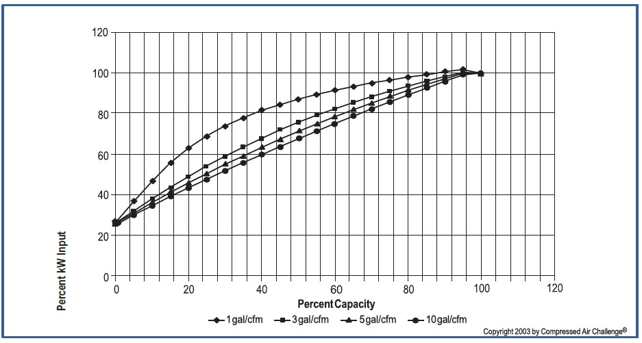
Most lubricant-injected rotary screw compressors are equipped with capacity control by inlet valve modulation designed to match the output from the air compressor with the demand from the points-of-use. On this basis, it has been stated that an air receiver is not needed. At best, this is misleading. An air receiver near the discharge of a rotary screw compressor will shield the compressor control system from pressure fluctuations from the demand side downstream of the receiver, and can allow the compressor to be unloaded for a longer period of time, during periods of light demand. The addition of an over-run timer (automatic dual control) can stop the compressor if it runs unloaded for a preset time, saving additional energy.
The top line in Figure 2.6 on the following page shows what would happen if inlet valve modulation was used without unloading the compressor.
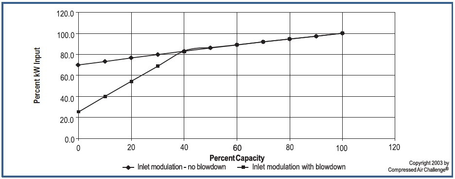
Approximately 70 percent of full-load power would still be used when modulation had reduced compressor output to zero. The second line shows inlet valve throttling to 40 percent capacity and unloading at that point. Figure 2.7, also on the following page, shows variable displacement (slide/turn/spiral/poppet valve) capacity reduction to 50 percent capacity followed by throttling to 40 percent capacity and unloading at that point.
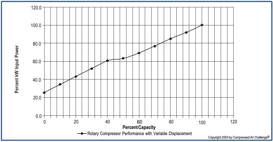
Variable speed may be achieved by variable frequency AC drives, or by switched reluctance DC drives. Each of these has its specific electrical characteristics, including inverter and other losses.
On the next page, Figure 2.8 shows how input power varies by percent capacity output for a lubricant-injected rotary screw compressor with variable speed control.
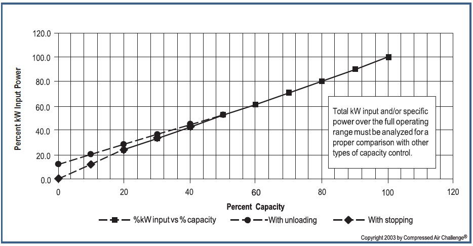
Air-end displacement is directly proportional to rotor speed, but air-end efficiency depends upon male rotor tip speed. Most variable speed drive (VSD) pack- age designs involve full capacity operation above the optimum rotor tip speed, at reduced air-end efficiency and increased input power, when compared with a constant speed compressor of the same capacity, operating at or near its optimum rotor tip speed. Efficiency with VSD is generally improved at reduced capacities. The best energy savings are realized in applications where the running hours are long, with a high proportion in the mid- to low-capacity range. Some designs stop the compressor when a lower speed of around 20 percent is reached, while others may unload at 40 to 50 percent, with an unloaded power of 10 to 15 percent. The appropriate amount of storage volume should be considered for each of these scenarios.
Field conversion of an existing compressor to variable speed drive must consider many factors, including the electric motor, the proposed male rotor tip speed at 100 percent capacity and the reduction of air-end efficiency at reduced speeds and capacity. The potential impacts of harmonics on other end-use equipment must also be considered.
It should be noted that in systems with multiple compressors and sequencing controls, it is possible to have most of the compressors running fully loaded on base load with only one compressor modulating (operating as the “trim” compressor), providing the most efficient mode for the system. In addition, it is not necessary to have the air receiver/system storage capacity based upon the total capacity of all the compressors, provided they are not all on the same load and unload pressure settings.
The capacity of the one compressor is either modulated or operated in load/unload control. This is also a good application for variable displacement, or compressors with variable displacement or VSD control to match system demand.
6: Compressed Air Storage
The basic purpose of an air receiver is to store a volume of compressed air for use when needed. As shown in Tip 5, for load/ unload compressors, adequate storage acts to effectively increase efficiency. Storage can also be used to:
- control demand events (peak demand periods) in a compressed air system by reducing both the amount of pressure drop and the rate of decay,
- protect critical pressure applications from other events in the system, and
- control the rate of pressure drop to end uses.
Many systems have an extra compressor operating inefficiently in modulation to support occasional demand events, and sometimes strategic storage solutions can allow for this compressor to be turned off.
Controls and System Performance
The most common example of using storage for control is a small, air-cooled, piston- type compressor, mounted on a “tank” or air receiver. The compressor operates on a start/stop control system, usually controlled by a pressure switch having a fixed differential. For automotive applications, the compressor is normally stopped at a pressure of 175 psig. The compressor is restarted when the regulated pressures for the end uses of the compressed air causes the pressure to fall to about 145 psig (a differential of 30 psi). The wide pressure band combined with the storage reduces the frequency of motor starts, thereby protecting the motor.
In industrial compressed air systems, the supply side is generally considered to be the air compressors, dryers, related filters and a primary air receiver. There are two differing points of view on the optimal location of a primary air receiver in a plant air system. If the receiver is located soon after the compressor discharge and the compressor(s) is a piston-type, the receiver acts as a dampener for pressure pulsations. If the receiver is located before the compressed air dryer, the receiver may provide additional radiant cooling and drop out some of the condensate and entrained oil, benefiting the dryer. However, the receiver will be filled with saturated air, and if there is a sudden demand that exceeds the capacity rating of the compressor and matching dryer, the dryer can be overloaded, resulting in a higher pressure dew point.
If the air receiver is located after the compressed air dryer, some of the above advantages are lost. However, the receiver is filled with compressed air (which has been dried), and a sudden demand in excess of the compressor and dryer capacity rating will be met with dried air. The dryer is not overloaded, since it is seeing only the output of the compressor, so the pressure dew point is not affected. One way to resolve this dilemma is to install storage both upstream and downstream of the dryer, remembering that the storage downstream of the dryer should be equal to or larger than the storage upstream of the dryer. In any case, it should be recognized that the compressed air dryer and associated filters will add pressure drop. This must be taken into account when determining the compressor discharge pressure to achieve the desired pressure that leaves the primary air receiver to the system.
The size of an air receiver can be calculated as follows:
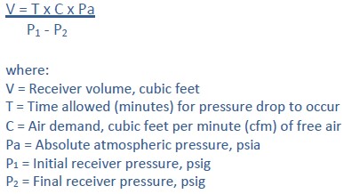
The formula assumes the receiver volume to be at ambient temperature and that no air is being supplied to the air receiver by the compressor(s). If the compressor(s) is running while air is being drawn from the receiver, the formula should be modified so that C is replaced by C – S, where S is the surplus compressor capacity, cfm of free air. The formula also can be revised with a known receiver size, to determine the time (T) to pump up an air receiver if the input flow is known. In this case, C is replaced by S, which is the compressor capacity, cfm of free air.
In the past, mainly with reciprocating compressors, the rule of thumb for sizing a primary air receiver has been from 1 gallon per cfm to 3 gallons per cfm of compressor capacity. This is no longer regarded as good practice, and the recommended primary receiver size will vary with the type of compressor and capacity control used.
Secondary Air Receivers
In many industrial plants, there will be one or more applications with an intermittent demand of relatively high volume. This can cause severe dynamic pressure fluctuations in the whole system, with some essential points-of-use being intermittently starved, impacting the operation of pressure critical compressed air powered equipment. In most cases the system pressure will be artificially raised, increasing energy consumption. One strategy to address this is correctly sizing and locating a secondary air receiver close to the point of high intermittent demand. Such demand is often of short duration, and the time between the demand events is such that there is ample time to replenish the secondary receiver pressure with- out adding compressor capacity. A check valve before the secondary air receiver will prevent back flow to the rest of the system and ensure that the required volume is stored to meet the anticipated event(s).
A strategy called high pressure offline storage can be used to reduce the size of the required storage that might be required to feed a high volume intermittent use. A high pressure source such as a booster or stand-alone compressor pumps up the storage to a pressure much higher than system pressure, utilizing a much larger storage differential. For example a 500 gallon storage receiver with a 100 psi storage differential contains the same amount of air as a 5,000 gallon receiver with a 10 psi differential. The effectiveness of this strategy varies as it take more energy to produce the high pressure air, but this might enable a spare running compressor to shut off, saving more energy and reducing electrical peak demand charges.
Correctly sized and located air receivers can provide major stability and reliability advantages in a compressed air system and require little maintenance. All pressure vessels should meet pressure vessel safety requirements and have appropriate pressure relief valves. An automatic drain device, with manual bypass for service, should also be included. Condensate removed should be decontaminated to meet appropriate federal, state and local codes.
7: Proven Opportunities at the Component Level
In some cases, taking a systems approach to analyzing compressed air systems can require more detailed analysis of an individual components as well as investigation of performance issues. In general, compressed air systems contain five major sub-systems: 1) compressors; 2) prime mover; 3) controls; 4) air treatment equipment and other accessories; and 5) the air distribution sub-system. Important performance aspects of each of these sub-systems are discussed in detail below.
Compressors
While there are many different types of compressors, all compressor types generally operate more efficiently for 80-150 psig systems if they are designed to include multiple stages. With multiple stages, the final discharge pressure is generated over several steps, thereby saving energy.
Many multi-stage compressors save energy by cooling the air between stages, reducing the volume and work required to compress the air. In spite of this, many industrial compressors only have a single stage because equipment manufacturing costs are lower. Performance and efficiency issues of the three most common types of compressors—single- and double-acting reciprocating compressors, rotary compressors, and centrifugal compressors—are discussed below.
Single- and Double-Acting Reciprocating Compressors. In the past, reciprocating air compressors were the most widely used in industrial plant air systems. Single-acting reciprocating compressors are generally air-cooled, in the smaller hp sizes, and do not require substantial foundations. These compressors are less efficient than other types at full load, but operate quite efficiently at part load. Double-acting reciprocating air compressors are generally water- cooled and require substantial foundations. Multi-stage versions are usually considered to be the most efficient air compressors, but have high initial and installation costs and higher maintenance requirements. Other than for specialty applications double-acting reciprocating compressors are increasingly being replaced by other compressors due to obsolescence, maintenance issues and lack of parts.
Rotary Compressors. Today, lubricant-injected rotary screw compressors are used in most industrial plant air applications and for large applications in the service industries. They have some advantages over reciprocating compressors, including lower initial installation and maintenance costs; smaller size; reduced vibration and noise; reduced floor space requirements. Rotary screw compressors provide continuous flow and do not have the type of pressure pulsations typically associated with reciprocating compressors.
Lubricant-injected rotary screw compressors are typically less efficient than two-stage, double-acting reciprocating compressors or three-stage centrifugal compressors. Two-stage rotary screw compressors are generally more efficient than single-stage units. In general, rotary screw compressors are also less efficient at part-load than reciprocating compressors.
A wide range of models is usually available from different manufacturers for any given application. A good efficiency measure is to select the most efficient model available at full output capacity. The selection of the compressor with the best part load power consumption characteristics for units that are not base loaded can also be an important consideration. Published Compressed Air and Gas Institute (CAGI) data sheets can be used to compare brands and types of screw compressors.
Centrifugal Compressors. The use of centrifugal compressors is usually limited to higher volume industrial plant applications, such as chemical, textile plants, petroleum refining, or general plant air systems in larger manufacturing facilities. The compressors operate at high speeds and therefore use smaller, more compact equipment. In larger sizes, three-stage centrifugal compressors are often more efficient than rotary screw compressors and can approach the efficiency levels of double-acting reciprocating compressors.
Centrifugal air compressors typically have 100 to 125 psig discharge pressures for industrial applications and are generally available from 150 hp to above 10,000 hp, generally with improving efficiency as the size increases. Centrifugal compressors are sometimes best suited to applications where demand is relatively constant or in industrial plants where they can be used primarily for base-load operation, allowing other compressor types to be as used as trim machines to meet peak demands. Best efficiency occurs if centrifugal compressors are operated at their best efficiency point and blow-off control is kept to a minimum.
Lubricant-Free Compressors. Lubricant-free versions of reciprocating and rotary air compressors are available. Centrifugal air compressors are inherently lubricant- free. Lubricant-free compressors may be appropriate for specific applications or to meet specific air quality requirements. Lubricant-free rotary screw and reciprocating compressors are generally less efficient than lubricant-injected machines.
Advantages and Disadvantages of Each Compressor Type
Advantages and disadvantages of any compressor are based on its characteristics and application. Advantages and disadvantages listed below are for a typical compressed air system in an industrial plant.
Single-Acting, Air-Cooled Reciprocating Air Compressors
Advantages include:
- Good part load efficiency
- Small size and weight
- Generally can be located close to point-of-use avoiding lengthy piping runs and pressure drops
- Do not require separate cooling systems
- Simple maintenance procedures
Disadvantages include:
- Lubricant carryover as piston rings wear, which should be avoided
- Relatively high noise
- Less efficient at full load
- Generally are designed to run not more than 50% of the time, although some can be at 80%
- Generally compress and store the air in a receiver at a pressure higher than required at the point-of- use. The pressure then is reduced to the required operating pressure, but without recovery of the energy used to compress to the higher pressure.
Operating Efficiency: 22 to 24 kW/100 cfm*
Double-Acting, Water-Cooled Reciprocating Air Compressors
Advantages include:
- Efficient compression, particularly with multi-stage compressors
- Three-step (0-50-100 percent) or five-step (0-25-
50- 75-100 percent) capacity controls, allowing efficient part-load operation - Relatively routine maintenance procedures
Disadvantages include:
- Obsolescence and lack of parts
- Relatively high first cost compared with equivalent rotary air compressors
- Relatively high space requirements
- Lubricant carryover, except on oil-free models
- Relatively high vibrations require high foundation costs
- Repair procedures require some training and skills
Operating Efficiency: 15 to 16 kW/100 cfm*
Lubricant-Injected Rotary Screw Compressors
Advantages include:
- Compact size and complete package
- Economic first cost
- Vibration-free operation does not require special foundation
- Part-load capacity control systems can match system demand
- Suitable for variable speed control with improved performance at part load)
- Routine maintenance includes lubricant and filter changes.
Disadvantages include:
- Part- load (efficiency can vary depending on control mode
- Lubricant carryover into delivered air requires proper maintenance of air/lubricant separator and the lubricant itself.
Operating Efficiency at 100 psig:
- 16 to 19 kW/100 cfm, single-stage*
- 15 to 17 kW/100 cfm, two-stage*
Lubricant-Free Rotary Screw Air Compressors
Advantages include:
- Completely packaged
- Designed to deliver lubricant-free air
- Do not require any special foundations.
Disadvantages include:
- Significant premium over lubricant-injected type
- Less efficient than lubricant-injected type
- Limited to load/unload capacity control and VSD
- Higher maintenance costs than lubricant-injected type over the life of the machine.
Operating Efficiency: 17 to 22 kW/100 cfm*
Centrifugal Air Compressors
Advantages include:
- Completely packaged for plant or instrument air through tens of thousands of horsepower sizes
- Relative first cost improves as size increases
- Designed to deliver lubricant-free air
- Do not require any special foundations.
Disadvantages include:
- Operation below 70-80 percent of capacity may require blow off to avoid surge, resulting in wasted energy. (Note: Load/unload may be possible)
- High rotational speeds require special bearings, sophisticated monitoring of vibrations and clearances
- Specialized maintenance considerations.
Operating Efficiency: 16 to 20 kW/100 cfm*
*By taking the estimated full-load bhp requirement of each compressor type at 100 psig discharge pressure at the compressor, a main-drive motor with a typical efficiency of 92 percent and 0.746 kW/bhp, the approximate efficiencies are obtained.
Prime Movers
The majority of industrial compressed air systems use electric motors as the prime mover. Most major manufacturers of industrial packaged compressed air systems now offer energy-efficient motors. There is a range of efficiencies available for any given application, and manufacturers will likely offer lines of premium efficiency motors that have higher efficiencies than standard-efficiency motors.
Motors can be flange-mounted, connected with a V-belt, or direct-coupled. Proper alignment is critical for all applications. Direct coupling or flange mounting results in the least loss of efficiency, while V-belt applications may allow for more compact packaging. V-belts should always be inspected and tensioned per manufacturer’s specification to avoid increased power transmission losses.
Because of the heavy-duty and load cycles on most compressors, it almost always makes sense to buy the most efficient motor available. The incremental cost for a more efficient motor is typically paid back in less than one year from the resulting energy savings. Users should be aware that new energy-efficient motors sometimes have lower available starting torque than standard motors and often have slightly higher operating speeds because of reduced slip. Match operating speeds and torque requirement as closely as possible when replacing a motor.
Controls
Compressor control mechanisms are used to match the compressed air volume and pressure delivered by the compressor with facility demand. Compressor controls are often the most important factor determining a compressor’s ability to perform efficiently at part- load. Controls are frequently configured poorly, and proper control strategies can lead to substantial reductions in energy consumption.
For more information on controls and compressed air system performance, see Tip 5: Compressed Air System Controls.
Air Treatment Equipment and Other
Accessories
Air treatment equipment must provide for both contaminant removal and preparation of the air for equipment use. The level of air treatment and accessories needed is often dependent on air quality requirements. For optimum performance, air treatment equipment should be operated as close to manufacturers’ design conditions as possible. Drying to unnecessarily low dew points or excessive filtration of compressed air can waste significant energy and possibly increased maintenance costs. A discussion of important compressor system accessory equipment and performance follows.
Dryers. Compressed air system performance is typically enhanced by the use of dryers, but since they require added capital and operating costs (including energy), drying should only be performed to the degree that it is needed for the proper functioning of the equipment and the end use.
Single-tower, chemical deliquescent dryers use little energy, but provide pressure dew point suppression of 15 to 50°F below the dryer inlet temperature, depending on the desiccant selected. The drying of the air consumes the desiccant which must be replaced at regular intervals. They are not suitable for most systems and are typically used only in specialty applications. The approximate power requirement, including pressure drop through the dryer and any associated filtration, but excluding the cost of replacement desiccant, is approximately 0.2 kW/100 cfm.
Refrigerant-type dryers are the most common and provide a pressure dew point of 35 to 39°F, which is acceptable for many applications. In addition to the pressure drop across the dryer (usually 3 to 5 psid), the energy to run the refrigerant compressor must be considered. Some refrigerant-type dryers have the ability to efficiently cycle on and off at lower than rated flows, which may save energy. The full load power requirement, including the effect of pressure drop through the dryer, is 0.79 kW/100 cfm. Cylinder head unloading dryers are also available (single and two-step) in larger dryers and offer improved part-load performance over conventional refrigerated dryers.
Twin-tower, desiccant-type dryers are the most effective in the removal of moisture from the air and typically are rated at a pressure dew point of –40°F. In a pressure-swing regenerative dryer, the purge air requirement can range from 10 to 18 percent of the dryer’s rating, depending on the type of dryer. This energy loss, in addition to the pressure drop across the dryer, must be considered. The heated-type requires less purge air for regeneration, as heaters are used to heat the desiccant bed or the purge air.
Heated blower type dryers use no purge air and a small amount for cooling. Some heated blower types use secondary cooling and zero purge. The heater (and blower) energy must also be considered against the reduction in the amount of purge air, in addition to the pressure drop. Approximate full-load power requirement, including pressure drop through the dryer, is 2.0 to 3.0 kW/100 cfm. Energy efficiency can be improved at part loads using dew point controls.
Heat-of-compression dryers are regenerative- desiccant dryers, which use the heat generated during compression to accomplish desiccant regeneration. Common types use desiccant drum or twin tower configuration. This means that there is no loss of purge air. This type of dryer requires air from the compressor at sufficiently high temperature to accomplish regeneration. For this reason, heat-of-compression dryers are used almost exclusively with centrifugal or lubricant-free rotary screw compressors. There is often no reduction of air capacity with this type of dryer except a very small percentage due to cooling purge.
The twin-tower, heat-of-compression dryer operation is similar to other twin-tower, heat-activated, regenerative desiccant dryers. The difference is that the desiccant in the saturated tower is regenerated by means of the heat of compression in all of the hot air leaving the discharge of the air compressor (aftercooler bypassed). The total air flow then passes through a secondary aftercooler before entering the drying tower. Temperatures must be high enough to regenerate the desiccant and may require secondary heat.
The total power requirement, including pressure drop and compressor operating cost (not including cooling purge or secondary heat, is approximately
0.8 kW/100 cfm.
Membrane-type dryers can achieve dew points of 40°F, but lower dew points to –40°F can be achieved at the expense of additional purge air loss. These dryers are suitable for small point-of-use applications where the air quality is greater than that of the general applications.
Advantages of membrane dryers include:
- Low installation cost
- No electrical consumption
- Can be installed outdoors
- Can be used in hazardous atmospheres
- No moving parts.
Disadvantages of membrane dryers include:
- Limited to low-capacity systems
- High purge air loss (15 to 20 percent) to achieve required pressure dew points
- Membrane may be fouled by oil or other contaminants and a coalescing filter is recommended before the dryer.
The total full-load power requirement, including pressure drop and compressor operating cost is approximately 3 to 4 kW/100 cfm. Efficiency can drop off drastically if used with very light loads. Use of energy saving controls can improve part load efficiency.
Dryer Selection. The selection of a compressed air dryer for the rated conditions should be based upon the required pressure dew point and the estimated cost of operation. Where a pressure dew point of less than 35°F is required, a refrigerant-type dryer cannot be used. The required pressure dew point for the application at each point- of-use eliminates certain types of dryers. Dryers must be sized by taking into account worst case operating inlet temperature, system pressure and ambient temperature. Where average loading conditions are less than the dryer rating, the selection of units with good part load efficiency through efficient control can save energy. Typically, the pressure drop through a compressed air dryer is 3 to 5 psi and should be taken into account in system requirements. Compressed air should be dried only where necessary and only to the pressure dew point required.
Compressed Air Filters. These include particulate filters to remove solid particles, coalescing filters to remove lubricant and moisture, and adsorbent filters for removal of odors and taste. A coalescing-type filter is recommended before a desiccant-type dryer to prevent fouling of the desiccant bed. A one micron after-filter is necessary to prevent desiccant “fines” from entering the distribution piping. Additional filtration may also be needed to meet requirements for specific end uses.
Compressed air filters downstream of the air compressor are generally required for the removal of contaminants, such as particulates, condensate, and lubricant. Filtration only to the level required by each compressed air application will minimize pressure drop and resultant energy consumption. Elements should also be replaced as indicated by pressure differential, and at least annually, to minimize pressure drop and energy consumption. Filters should be installed with efficient condensate drains.
Air Receivers. The storage of compressed air in air receivers is a critical component to any compressed air system. Air receivers are designed to provide a supply buffer to meet short-term demand spikes that can exceed the compressor capacity. They also serve to dampen reciprocating compressor pulsations, separate out particles and liquids, and make the compressed air system easier to control. In some cases, installing a larger receiver to meet occasional peak demands can even allow for the use of a smaller compressor.
In most systems, the receiver will be located just after the dryer. In some cases, it makes sense to use multiple receivers, one prior to the dryer and one closer to points of intermittent use. Refer to Tip 6: Compressed Air Storage for additional information.
Condensate/Lubricant Separators. It is no longer acceptable to discharge condensate from a compressed air system to sewer lines without treatment to remove contaminants such as entrained lubricants (except for condensate from some lubricant-free compressor systems). Condensate/lubricant separators are available in the marketplace to achieve separation by means of settling tanks and/or permeable membranes. This equipment helps to avoid the potentially high costs of contaminated waste disposal.
Air/Lubricant Separators. The air/lubricant separator in a lubricant-cooled, rotary screw compressor generally starts with a 2 to 3 psid pressure drop at full-load when new. Higher pressure differentials cause the compressor motor to consume more energy and possibly exceed the service factor. Maintenance manuals usually suggest changing them when there is a 10 to 12 psid pressure drop across the separator. In many cases it may make sense to make an earlier separator replacement, especially if electricity prices are high.
Heat Recovery Systems. Most systems do not employ heat recovery, even though economics can be good, with typical paybacks of less than one year. Heat recovery systems require electricity for fans or pumps, but can decrease the need for fossil fuels usually used for heating. See the Tip 9: Heat Recovery and Compressed Air Systems for more information on this energy saving opportunity.
The Air Distribution Sub-System
The air distribution sub-system, which connects the major components, is one of the most important parts of the compressed air system. It is made up of main trunk lines, hoses and valves, drops to specific usage points, pressure regulators and lubricators, additional filters and traps, and supplementary air treatment equipment. It is throughout this sub-system that most leaks occur, energy is lost, and maintenance is required. Equipment should be chosen to avoid excessive pressure drops and leakage.
In addition, consideration of appropriate sizing of equipment and layout will provide for proper air supply, good tool performance, and optimal production. The complete drying, filtration, and distribution system should be properly sized and arranged so that the total pressure drop from the air compressor to the points- of-use is much less than 10 percent of the compressor discharge pressure.
Some users bypass automatic condensate traps and leave valves partially open at all times to allow for constant draining. This practice wastes substantial energy and should never be undertaken. If a float- operated, automatic condensate drain is not functioning properly, it should be cleaned and repaired instead of bypassed. If maintenance of float-operated drain traps is a burden, consider replacing them with more reliable demand- type drain traps.
The efficiency of the entire system can be enhanced by the proper selection, application, installation, and maintenance of each component.
8: Maintenance of Compressed Air Systems for Peak Performance
Like all electro-mechanical equipment, industrial compressed air systems require periodic maintenance to operate at peak efficiency and minimize unscheduled downtime. Inadequate maintenance can have a significant impact on energy consumption via lower compression efficiency, air leakage, or pressure variability. It can also lead to high operating temperatures, poor moisture control, and excessive contamination. Most problems are minor and can be corrected by simple adjustments, cleaning, part replacement, or the elimination of adverse conditions. Compressed air system maintenance is similar to that performed on cars; filters and fluids are replaced, cooling water is inspected, belts are adjusted, and leaks are identified and repaired.
All equipment in the compressed air system should be maintained in accordance with manufacturers’ specifications. Manufacturers provide inspection, maintenance, and service schedules that should be strictly followed. In many cases, it makes sense, from efficiency and economic standpoints, to maintain equipment more frequently than the intervals recommended by manufacturers, which are primarily designed to protect equipment.
One way to tell if a system is well-maintained and operating properly is to periodically baseline the system by tracking power, pressure, flow, and temperature. If power use at a given pressure and flow rate increases, the system’s efficiency is degrading. This baselining will also indicate if the compressor is operating at full capacity, and if the capacity is decreasing over time. On new systems, specifications and operating data should be recorded when the system is first set up and operating properly. See Tip 10: Baselining Compressed Air Systems for more information.
Proper maintenance is essential to compressed air system efficiency and reliability. The key to success requires compressor operators to determine the requirements for each piece of equipment, the necessary resources, and trend analysis of recorded data. All observations and meter readings should be recorded for compressors, dryers, filters, and any components in the compressor plant. The combination of equipment control panel data, frequent inspections, and log sheets are required to avoid unscheduled system shutdowns, and to utilize the principles of preventive and predictive maintenance. Recording the dates of all maintenance and repairs, including a list of all parts that were replaced or serviced is recommended.
The maintenance schedules provided in this Tip are intended to be used only as a guide. For more exact procedures, always refer to the manufacturer’s manuals and follow all safety precautions.
Stopping for Maintenance
The following procedures should be followed when stopping the compressor for maintenance or service.
Step 1. Per Occupational Safety & Health Administration (OSHA) regulation 1910.147: The Control of Hazardous Energy Source (Lockout/Tagout), disconnect and lockout the main power source. Display a sign in clear view at the main power disconnect switch stating that the compressor is being serviced.
WARNING!
Never assume a compressor is safe to work on just because it is not operating. It could restart at any time.
Step 2. Isolate the compressor from the compressed air supply by closing a manual shutoff valve down- stream (and upstream, if applicable in booster service) from the compressor. Display a sign in clear view at the shutoff valve stating that the compressor is being serviced. Be certain that a pressure relief valve is installed upstream of any isolation valve.
Step 3. Lock open a pressure relief valve within the pressurized system to allow the system to be completely depressurized. NEVER remove a plug to relieve the pressure!
Step 4. Shut off the water cooling supply (water- cooled compressors).
Step 5. Open all manual drain valves within the area to be serviced.
Step 6. Wait for the unit to cool before starting to service. (Temperatures of 125°F can burn skin. Some surface temperatures exceed 350°F when the compressor is operating, and just after it is shut down).
Step 7. Refer and give preference to the manufacturer’s manuals over these typical maintenance procedures.
Maintenance Schedules
To assure maximum performance and service life of your compressor, a routine maintenance schedule should be developed. Sample schedules have been included here to help you to develop a maintenance schedule designed for your particular application. Time frames may need to be shortened in harsher environments.
The documentation shipped with your compressor should contain a maintenance schedule checklist. Make copies of this checklist and retain the master to make more copies as needed. On each copy of the checklist, enter dates and initials in the appropriate spaces. Keep the checklist and this Tip readily available near the compressor.
General Maintenance Discussion
All equipment in the compressed air system should be maintained in accordance with manufacturers’ specifications. Manufacturers provide inspection, maintenance, safety, service schedules and pressure relief valve testing that should be strictly followed.
Maintenance issues for specific system components are discussed below.
Lubricant-Injected Rotary Screw Compressor Package
The main areas of the compressor package that need maintenance are the compressor, heat exchangers air-lubricant separator, lubricant, lubricant filter, and air-inlet filter. The compressor and all coolers need to be kept clean and foul-free. If they are dirty, compressor efficiency will be adversely affected. Cooling fans and water supplies should also be inspected to ensure that they are operating at peak performance.
The air lubricant separator in a lubricant-cooled, rotary screw compressor generally starts with a 2 to 3 psid pressure drop at full-load when new. Maintenance manuals usually suggest changing them when there is about a 10 psid pressure drop across the separator. In many cases it may make sense to make an earlier separator replacement, particularly if electricity prices are high.
The compressor lubricant and lubricant filter should be changed per manufacturer’s specification. Lubricant can become corrosive and degrade both the equipment and system efficiency. Lubricant sampling and analysis is recommended.
For lubricant-injected rotary compressors, the lubrication is provided to bearings, gears, and inter- meshing rotor surfaces. The lubricant also acts as a seal and removes most of the heat of compression. Only a lubricant meeting the manufacturer’s specifications should be used.
Inlet filters and inlet piping should also be kept clean. A dirty filter can reduce compressor capacity and efficiency. Filters should be maintained at least per manufacturer’s specifications, taking into account the level of contaminants in the facility’s air.
Compressor Drives
If the electric motor driving a compressor is not properly maintained, it will not only consume more energy, but will be apt to fail before its expected life- time. The two most important aspects of motor maintenance are lubrication and cleaning.
Lubrication. Too much lubrication can be just as harmful as too little and is a major cause of premature motor failure. Motors should be lubricated per the manufacturer’s specification, which can be anywhere from every 2 months to every 18 months, depending on annual hours of operation and motor speed.
Cleaning. Since motors need to dissipate heat, it is important to keep all of the air passages clean and free of obstruction. For enclosed motors, it is vital that cooling fins are kept free of debris. Poor motor cooling can increase motor temperature which shortens motor life and increases energy consumption.
Belts. Motor V-belt drives also require periodic maintenance. Tight belts can lead to excessive bearing wear, and loose belts can slip and waste energy. Under normal operation, belts stretch and wear and therefore, require adjustment. A typical rule of thumb is to examine and adjust belts after every 400 hours of operation. Follow manufacturers recommended tension requirements.
Air Treatment Equipment
Fouled compressed air treatment equipment can result in excessive energy consumption as well as poor-quality air that can damage other equipment. All filters should be kept clean. Dryers, aftercoolers, and separators should all be cleaned and maintained per manufacturer’s specifications.
Automatic Condensate Drain Traps. Most compressed air systems have numerous moisture traps located throughout the system. Traps need to be inspected periodically to ensure that they are not stuck in either the open or closed position. An automatic trap stuck in the open position will leak compressed air; a trap stuck in the closed position will cause condensate to back up and be carried downstream where it can damage other system components. Traps stuck in the open position can be a major source of wasted energy.
End-Use Filters, Regulators, and Lubricators. Point-of- use filters, regulators, and lubricators are needed to ensure that a tool is receiving a clean, lubricated supply of air at the proper pressure. Filters should be inspected periodically because a clogged filter will increase pressure drop, which can either reduce pressure at the point-of-use or increase the pressure required from the compressor, thereby consuming excessive energy. A filter that is not operating properly will also allow contaminants into a tool, causing it to wear out prematurely. The lubricant level should also be checked often enough to ensure that it does not run dry. Tools that are not properly lubricated will wear prematurely and use excess energy.
Leaks
Leak detection and repair is an important part of any maintenance program. For more information on finding and fixing leaks, see Tip 3: Compressed Air System Leaks.
Temperature
Temperature measurements help to indicate if equipment is operating at peak performance. Generally, equipment that runs hotter than specified parameters is not performing at peak efficiency and requires service. The following temperature measurements should be taken when baselining a system.
- Aftercooler and intercoolers cold temperature difference or approach temperature of cold water inlet to cooled air outlet. Because dryers are normally designed at 100°F maximum inlet air temperature, some remedial action may be required if aftercooler outlet temperatures exceed 100°F.
- For rotary-lubricated compressors, the air discharge temperatures must be maintained for reliable compressor performance. Normal operation requires temperatures below 200°F.
- Inlet air temperature.
Maintenance Schedules
Establishing a regular, well-organized maintenance program, and strictly following it, is critical to maintaining the performance of a compressed air system. One person should be given the responsibility of ensuring that all maintenance is performed properly, on schedule, and is adequately documented.
The following are typical recommended minimum maintenance procedures for air-cooled reciprocating compressors; water-cooled, double-acting reciprocating compressors; lubricant-injected rotary compressors; lubricant-free rotary compressors; and centrifugal compressors.
Air-Cooled Reciprocating Compressors
Every 8 Hours (or Daily)
- Maintain lubricant level between high- and low-level marks. (Discoloration or a higher lubricant level reading may indicate the presence of condensed liquids). If lubricant is contaminated, drain and replace.
- Drain receiver tank, drop legs and traps in the distribution system.
- Give compressor an overall visual inspection and be sure safety guards are in place.
- Check for any unusual noise or vibration.
- Check lubricant pressure on pressure lubricated units.
- Check for lubricant leaks.
Every 100 Hours (or Weekly)
- Be certain pressure relief valves are working.
- Clean the cooling surfaces of the intercooler and compressor.
- Check the compressor for air leaks.
- Check the compressed air distribution system for leaks.
- Clean or replace the air intake filter. Check more often under dusty conditions.
- Check belt tension.
As required by manufacturer
- Change lubricant in accordance with manufacturer’s instructions. (more frequently in harsher environments).
- Check lubricant filter on pressure lubricated units (more frequently in harsher environments).
- When synthetic lubricant is used, lubricant change intervals may be extended.
- Inspect compressor valves for leakage and/or carbon build-up. The lubricant sump strainer screen inside the crankcase of pressure-lubricated models should be thoroughly cleaned with a safety solvent during every lubricant change. If excessive sludge build-up exists inside the crankcase, clean the inside of the crankcase as well as the screen. Never use a flammable or toxic solvent for cleaning. Always use a safety solvent and follow the directions provided.
Every 2,000 Hours (or 12 Months)
- Inspect the pressure switch contacts, diaphragm and motor starter contacts.
Lubrication
Compressors may be shipped without lubricant in the crankcase. Before starting the compressor, add enough lubricant to the crankcase to register between the high and low marks on the dipstick or on bull’s eye sight gauge. Use the specified lubricant or consult the manufacturer for recommendations.
Certain synthetic lubricants have proven under extensive testing to minimize friction and wear, limit lubricant carryover, and reduce carbon and varnish deposits. They will support the performance characteristics and life and are highly recommended. Refer to the manufacturer’s specifications to determine the correct amount of lubricant and viscosity to use for your model and application. Use the supplier’s lubricant analysis program.
Routine Maintenance for Water-Cooled, Double-Acting Reciprocating Compressors
The following are typical minimum maintenance requirements for this type of compressor.
Every 8 Hours (or Daily)*
- Check compressor lubricant level in crankcase and cylinder lubricator and, if necessary, add to level indicated by sight gauge.
- Check cylinder lubrication feed rate and adjust, as necessary.
- Check lubricant pressure and adjust as necessary to meet specified operating pressure.
- Check cylinder jacket cooling water temperatures.
- Check capacity control operation. Observe discharge pressure gauge for proper load and unload pressures.
- Drain control line strainer.
- Check operation of automatic condensate drain trap (intercooler and aftercooler).
- Drain condensate from discharge piping as applicable (drop leg and receiver).
- Check intercooler pressure on multi-stage machines, and refer to manufacturer’s manual if pressure is not as specified.
Every 360 Hours (or Monthly)*
- • Check piston rod packing for leaks and for blow-by at gland. Repair or replace as necessary per manufacturer’s manual.
• Inspect lubricant scraper rings for leakage. Replace as necessary per manufacturer’s manual.
• Inspect air intake filter. Clean or replace as necessary.
• Drain lubricant strainer/filter sediment.
• Lubricate unloader mechanism per manufacturer’s manual.
• Check motor amperes (amps) at compressor full capacity and pressure.
Every 3,000 Hours (or Semi-Annually)*
- Perform valve inspection per manufacturer’s manual.
- Inspect cylinder or cylinder liner, through valve port, for scoring.
- Change crankcase lubricant, if required.
- Clean crankcase breather, if provided.
- Change lubricant filter element.
- Remove and clean control air filter/strainer element.
- Check all safety devices for proper operation.
- Perform piston ring inspection on non-lubricated design. Replace as necessary per manufacturer’s manual.
Every 6,000 Hours (or Annually)*
- Remove and clean crankcase lubricant strainer.
- Check foundation bolts for tightness. Adjust as necessary.
- Perform piston ring inspection. Replace as necessary per manufacturer’s manual.
*Whichever interval is sooner. Experience gained from a well-kept maintenance log may allow the recommended times to be adjusted.
Routine Maintenance for Lubricant Injected Rotary Compressor
The following are typical minimum maintenance requirements.
Periodically/Daily
Monitor all gauges and indicators for normal operation.
- Check lubricant level and top off as necessary.
- Check for lubricant leaks.
- Check for unusual noise or vibration.
- Drain water from air/lubricant reservoir.
- Drain control line filter.
Monthly
- Service air filter as needed (more often if extremely dusty conditions exist).
- Wipe down entire unit to maintain appearance.
- Check drive motor amps at compressor full capacity and design pressure.
- Check operation of all controls.
- Check operation of lubricant scavenger/return system. Clean, as necessary.
6 Months or Every 1,000-2000 Hours
- Take lubricant sample and have it analyzed.
- Change lubricant filter.*
Periodically/Annually
- Inspect the entire package and check all bolts for tightness.
- Change air/lubricant separator.
- Change lubricant per manufacturer’s instructions.
- Change air filter.
- Lubricate motors per manufacturer’s instructions.
- Check safety shutdown system. Contact authorized service person.
*Manufacturers may recommend changing the lubricant filter within the first week of operation to rid the system of foreign matter which may have collected during initial assembly and start-up.
Routine Maintenance for Lubricant-Free Rotary Screw Compressor
The following are typical minimum requirements for this type of compressor. Routine maintenance is relatively minimal. The microprocessor control panel monitors the status of the air and lubricant filters. When maintenance to either device is required, the control panel may display the appropriate maintenance message and flash the location on the display as a visual remainder.
Do not remove caps, plugs, and/or other components when compressor is running or pressurized. Stop compressor and relieve all internal pressure before doing so.
Daily
Following a routine start, observe the various control panel displays and local gauges to check that normal readings are being displayed. Previous records are very helpful in determining the normalcy of the measurements. These observations should be made during all expected modes of operation (i.e., full-load, no-load, inter-stage and discharge pressures, motor amps and cooling water temperatures).
After Initial 50 Hours of Operation
Upon completion of the first 50 hours of operation, essential readings of operating conditions should be verified and any necessary adjustments made.
Every 3,000 Hours of Operation
The following items should be checked every 3,000 hours of operation, although service conditions, such as relative cleanliness of process air or quality of cooling water, may require shorter inspection intervals.
- Check/change lubricant charge and filter element.
- Check/change air filter element.
- Check/change sump-breather filter element.
- Check/clean control line filter element.
- Check/clean condensate drain valve.
- Check condition of shaft coupling element and tightness of fasteners.
- Measure and record vibration signatures on compressor, gearbox, and motor (optional).
- Annual rebuilding of the inlet valve is normally recommended.
Note: Please refer to the motor manufacturer’s documentation for recommended maintenance. Keep in mind that the specified type and quantity of lubricating grease for motor bearings is crucial.
Every 15,000 Hours of Operation
In addition to those items covered in the 3,000-hour maintenance interval, the following items must also be checked every 15,000 hours of operation, depending upon conditions of service.
- Operate/test all safety devices.
- Check/clean heat exchangers.
- Check/clean blowdown valve.
- Check operation of balancing switch/valve assembly.
- Check/clean water regulating valve.
- Check/clean check valve.
- Check/clean galvanized interstage pipe work.
- Check condition of isolation mounts under compressor unit and motor.
- Check/clean strainer and check valve included in lubricant pump suction line, inside lubricant sump.
Be aware that work on the compressor stages and gearbox must be conducted by manufacturer’s personnel only. Any work done by unauthorized personnel can render the manufacturer’s equipment warranty null and void.
Parts Replacement and Adjustment Procedures
Familiarize yourself with the safety guidelines offered in the safety section of the manufacturer’s manual before attempting any maintenance on the package.
Routine Maintenance for Centrifugal Air Compressors
The following are typical maintenance requirements for this type of compressor.
Daily
- Record operating air inlet, interstage and discharge pressures and temperatures.
- Record cooling water inlet and outlet pressures and temperatures.
- Record lubricant pressure and temperatures.
- Record all vibration levels.
- Check inlet air filter differential pressure.
- Check proper operation of drain traps.
- Drain control air filter.
- Check for leaks, air, water, and lubricant. Repair and clean as necessary.
- Check lubricant sump level and adjust as necessary.
- Check drive motor for smooth operation and record amps.
Every 3 Months
- Check lubricant filter differential pressure. Replace element as necessary.
- Check lubricant sump venting system. Replace filter elements as necessary.
- Check operation of capacity control system.
- Check operation of surge control system.
- Check main-drive motor amps at full-load operation.
- Check automatic drain traps and strainers. Clean and/or replace as necessary.
Every 6 Months
- Check inlet air filter and replace element as necessary.
- Take oil sample for analysis. Replace lubricant as necessary.
Annually
- Inspect intercooler, aftercooler, and lubricant cooler. Clean and/or replace as necessary.
- Inspect main drive motor for loose mounting bolts, frayed or worn electrical cables, and accumulated dirt. Follow manufacturer’s recommendations, including lubrication.
- Inspect main drive coupling for alignment and required lubrication.
- Inspect gearbox for loose mounting bolts, vibration, unusual noise or wear and axial clearances per manufacturer’s manual.
- Check impeller inlets and diffusers for signs of wear, rubbing or cracking.
- Check control panel for complete and proper operation.
- Check all control valves for proper operation.
- Check all safety devices for proper settings and operation.
- Inspect check valve; replace worn parts.
Keep all components/accessories clean and follow all recommended safety procedures.
9: Heat Recovery and Compressed Air Systems
As much as 80 to 93 percent of the electrical energy used by an industrial air compressor is converted into heat. In many cases, a properly designed heat recovery unit can recover anywhere from 50 to 90 percent of this available thermal energy and put it to useful work heating air or water.
Typical uses for recovered heat include supplemental space heating, industrial process heating, water heating, makeup air heating, and boiler makeup water preheating. Recoverable heat from a compressed air system however, is usually not hot enough to produce steam directly.
Heat recovery systems are available for both air- and water-cooled compressors.
Heat Recovery with Air-Cooled, Rotary Screw Compressors
Heating Air. Air-cooled, packaged, rotary screw compressors are very amenable to heat recovery for space heating or other hot air uses. Ambient atmospheric air is heated by passing it across the system’s aftercooler and lubricant cooler, where it extracts heat from both the compressed air and the lubricant that is used to lubricate and cool the compressor.
Because packaged compressors are typically enclosed in cabinets and already include heat exchangers and fans, the only system modifications needed are the addition of ducting and possibly another fan to handle the duct loading and to eliminate any back pressure on the compressor cooling fan. These heat recovery systems can be modulated with a simple, thermostatically controlled hinged vent. When heating is not required —such as in the summer months—the hot air can be ducted outside the building. The vent can also be thermostatically regulated to provide a constant temperature for a heated area.
Hot air can be used for space heating, industrial drying, preheating aspirated air for oil burners, or any other application requiring warm air. As a rule, approximately 50,000 British thermal units (Btu) per hour of energy is available for each 100 cfm of capacity (at full-load). Air temperatures of 20 to 40°F above the cooling air inlet temperature can be obtained. Recovery efficiencies of 80 to 90 percent are common.
Caution should be applied if the supply air for the compressor and the recovered heat is used in another space, because this can cause a decrease in the static pressure in the cabinet and reduce the efficiency of the compressor. Under this scenario, the user may want to consult a ventilation expert.
Heating Water. Using a heat exchanger, it is also possible to extract waste heat from the lubricant coolers found in packaged water-cooled, reciprocating or rotary screw compressors and produce hot water. Depending on design, heat exchangers can heat non-potable (gray) or potable water. When hot water is not required, the lubricant is routed to the standard lubricant cooler.
Hot water can be used in central heating or boiler systems, industrial cleaning processes, plating operations, heat pumps, laundries, or any other application where hot water is required. Heat exchangers also offer an opportunity to produce hot air and hot water, and allow the operator some ability to vary the hot air/hot water ratio.
Heat Recovery with Water-Cooled Compressors
Heat recovery for space heating is not as common with water-cooled compressors because an extra stage of heat exchange is required and the temperature of the available heat is lower. Because many water-cooled compressors are quite large, however, heat recovery for space heating can be an attractive opportunity. Recovery efficiencies of 50 to 60 percent are typical.
Calculating Energy Savings
When calculating energy savings and payback periods for heat recovery units, it is important to compare heat recovery with the current source of energy for generating thermal energy, which may be a low-price fossil fuel, such as natural gas. The equations in the text box on the next page illustrate the annual energy and costs savings available by recovering heat for space heating from an air-cooled, rotary screw compressor.
Applications where the existing heater is less than 85 percent efficient will see proportionally higher savings.
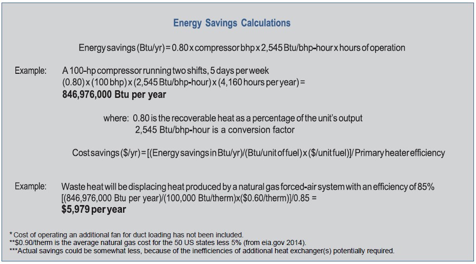
10: Baselining Compressed Air Systems
The purpose of baselining is to establish current energy performance levels and costs of a compressed air system, and to correlate the results with your plant’s present production levels. These measurements should be done at the same time as the pressure and flow measurements discussed in Section 1 “Analyzing Compressed Air Needs”. As you make improvements to your system, it will be possible to estimate the success by comparing the new measurements with the original baseline. Baselining a compressed air system and ongoing monitoring of energy performance may be part of an energy management system as specified by ISO50001 standard.
First, measurements of the system need to be taken. This requires the measurement of power, pressure, and flow. These measurements will be used in calculations to baseline system performance and energy consumption correlated to the plant production levels. Correlation to plant production levels is required to normalize data and perform an “apples-to-apples” comparison.
Energy saving measures implemented on both the supply and demand sides of the system, combined with proper compressor controls, will result in reduced energy consumption. This should be documented through continued measurements, again correlated to your plant’s production levels.
Some companies will also benchmark their compressed air systems against similar plants in their company, and sometimes even compare individual compressors.
Tools Needed
Properly baselining and monitoring a compressed air system requires the right tools. The following tools are required.
- Matched, calibrated pressure gauges or differential pressure gauges.
- Hook-on amp/volt meter (or preferably a kW meter).
- Data loggers—Data loggers are used in conjunction with other measurement devices to record multiple readings over a period of time. Data loggers are used to create plant pressure, flow, and energy consumption profiles, and can be important tools in developing a control strategy for a compressed air system.
- Flow meter—Factors to consider in selecting flow meters include type (in-line or insertion), air quality (wet or dry), ease of installation, life cycle cost (including possible pressure drop, such as orifice plates and maintenance), and accuracy
(repeatability and turndown range).
What to Measure
Baselining a system requires measurement of power, pressure, flow, and temperature under different operating conditions, and also estimating leak load. Each is discussed below. Please refer to all operation and safety instructions provided with measurement equipment before using it.
Power
Power is measured in order to estimate the annual energy consumption of a compressed air system. Basic spot power rough estimation can be done using a hook-on amp/volt meter or a wattmeter. The current and voltage into the compressor package should be measured. Full-load and no-load input power to the compressor should be measured.
For three-phase systems, power can be estimated by the following equation.
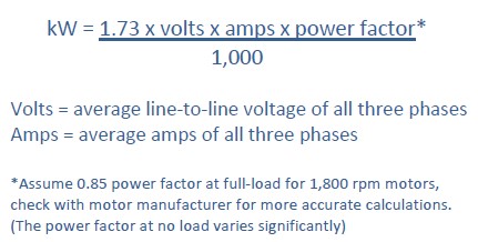
In general, spot measurement of amps and volts is only suitable for a basic rough estimation of annual energy consumption. Using a wattmeter in conjunction with data logging provides a more accurate direct reading of kW with no calculation or power factor adjustment.
Pressure
Pressure is measured to give feedback for control adjustments, and to determine pressure drops across equipment. Measurement of pressure through all operating conditions can uncover system performance issues that can be corrected to improve energy performance and system pressure stability. Calibrated measuring instruments are required, preferably used with a data logging system. The following pressure measurements should be taken when baselining a system.
- Inlet to compressor (monitor inlet filter)
- Differential across air/lubricant separator for a lubricated rotary compressor
- Interstage on multistage machines
- Pressure differentials, including
- Aftercooler
- Treatment equipment (dryers, filters, etc.)
- Various points in the distribution system.
Flow
Flow meters are necessary to measure total flow and to determine compressed air consumption. Flow, in conjunction with power or energy input, can be used to calculate the system specific power, or the amount of power consumed for a given flow output.
Flow should be measured:
- On the main compressor room output during all shifts
- At potential inappropriate uses to determine waste and as energy savings measures are implemented (for leaks during non-production periods)
Flow meters of the mass flow design will compensate for pressure and temperature variations and, if practical, should be suitable to measure the output of each individual compressor in the system. The mass flow is based upon standard reference conditions, which should be checked for the specific instrument used.
Using Power, Pressure, and Flow to Baseline System Performance and Energy Consumption
Using the techniques described previously, determine both cfm at psig and energy consumption (kW x hours) per unit of production. Always correlate to production levels for a true measure of air compressor system performance.
Other parameters to monitor over time include:
- Specific Power (cfm per kW or kW per 100 cfm) at a given pressure
- Pressure (psig)
- Pressure drop across various components.
The expectation is that as efficiency measures are implemented, the total energy use will be reduced. This assumes, of course, that production does not increase with a corresponding increase in the compressed air consumption. In general, improvements to compressor room efficiency through improved control reduce both the specific power and energy. Demand side flow reductions mostly affect the total energy with slight adjustment of the specific power. If flow reductions are made, and the pressure increases while energy consumption stays the same, adjust controls appropriately.
Estimating Leak Load
The ongoing measurement of leakage levels is an important part of baselining a compressed air system. Where appropriate, leakage levels can be tested during production downtime where compressed air consuming machines are turned off and all that remains is leakage flow. Leakage can be measured using flow meters, by observing the duty cycle of air compressors during non-productive periods or by doing a receiver blow down test. Procedures for leak estimation are shown in Tip 3: Compressed Air System Leaks.
11: Determining Your Compressed Air System Analysis Needs
A compressed air system analysis can highlight the true costs of compressed air and identify opportunities to improve efficiency and productivity.
Compressed air system users should consider using an auditor to analyze their compressed air system. A number of firms specialize in compressed air system analysis. System analysis is also performed by electric utilities, equipment distributors and manufacturers, energy service companies, and engineering firms. An informed consumer should be aware that the quality and comprehensiveness of system analysis can vary. Independent auditors should provide recommendations that are systems-neutral and commercially impartial. Independent auditors should neither specify nor recommend any particular manufacturer’s products.
A comprehensive compressed air system analysis should include an examination of both air supply and usage and the interaction between the supply and demand. Auditors typically measure the output of a compressed air system, calculate energy consumption in kilowatt-hours, and determine the annual cost of operating the system. The auditor may also measure total air losses caused by leaks and locate those that are significant. All components of the compressed air system are inspected individually and problem areas are identified. Losses and poor performance caused by system leaks, inappropriate uses, demand events, poor system design, system misuse, and total system dynamics are calculated, and a written report with a recommended course of action is provided.
The Compressed Air Challenge® (CAC) has developed guidelines to define three levels of system analysis services, independent of the type of firm offering these services. These three levels of service include: a walk- through evaluation (1/2 to 2 days), a system assessment (2 to 5 days), and a fully-instrumented audit (3 to
10 days).
Selecting a Service Provider
In selecting a service provider, a compressed air user should consider the following outlined below.
This information is also taken from the CAC’s Guidelines for Selecting a Compressed Air Service Provider.
Familiarity with the Systems Approach. The CAC provides Fundamentals of Compressed Air Systems and Advanced Management of Compressed Air Systems training to end users and service providers. One way to gauge a service provider’s commitment to the systems approach is whether they have staff who have received CAC training. If they do, ask whether these individuals will be providing or supervising services for your facility. Providers who are familiar with using a systems approach are much more likely to address situations, both inside and outside the compressor room, that affect the reliability of your compressed air supply.
Availability of Compressed Air System Analysis Services. Does the provider offer compressed air system analysis services? If yes, how well do these services fit your needs? If no, can the provider outsource these services to an experienced system specialist? How experienced are the individuals who will be providing these services? Once a walk-through, assessment, or audit is performed, what kind of follow-up services are available to ensure that the recommendations are properly implemented and produce the desired results? Ask for a sample of similar work that the provider has done for others, résumés of the personnel who will be performing the work, and client references. Please note that while leak detection is a useful element of a system assessment, a true system assessment should include much more. See www.compressedairchallenge.org for additional guidance.
Important Note: Recommendations resulting from system analysis activities should provide product- neutral solutions to system problems and include, only if needed, performance-based rather than brand- based equipment recommendations.
Compressor Knowledge and Expertise. Does the service provider have the expertise to work on your equipment? Can the service provider work on all types of compressors in your facility? How much experience do the service technicians have? How are the service technicians trained? Is formal schooling involved? Knowledgeable service technicians are worth the premium price they may demand because of their ability to troubleshoot and get equipment back on line efficiently and effectively.
System Components and Controls Knowledge and Expertise.
- Treatment, accessory, and ancillary equipment—Does the service provider have the expertise to perform refrigeration and other work on dryers and related equipment? Is the service provider capable of servicing the types of filters, drains, distribution and point-of-use equipment found in your facility?
- System controls—Does the service provider have the diagnostic and technical controls capability to determine how to optimize your existing control configuration and make recommendations for improvements? Can they help network compressors together or remotely monitor, if necessary? Advanced controls can save energy as well as improve reliability through automatic start and stop, as well as turning compressors off that can then serve as back-ups. Advance warning through remote monitoring may help identify a problem before it turns into a major shutdown.
Company Capabilities. Ask about the standards of performance that the prospective service provider has established for:
- Emergency service response
- Parts shipments
- Other factors which may influence your decision, such as:
- Installation capabilities internally or through a mechanical contractor
- Emergency rental fleet availability—electric or portable diesel driven
- Your company may request information on the service provider’s:
- Financial stability
- Insurance coverage
- Compliance with specific government regulations or those of your company.
Service Facilities. Visit the facilities of two or three service providers under consideration to see first-hand the type of repair shop and parts warehouse with which you will be dealing.
Important aspects of a basic compressed air system audit are discussed below.
System Issues
System issues go beyond examining the performance of an individual compressed air system component and, instead, examine how components on both the supply and demand sides of the system interact. Auditors typically address a number of systems issues. These are discussed below, and many are addressed in more detail in other compressed air systems fact sheets.
Level of Air Treatment. The auditor typically examines the compressed air applications and determines the appropriate level of air treatment required for proper operation of the equipment. Actual air quality levels are then measured. If the air is not being treated enough, alternative treatment strategies are recommended. If the air is being over-treated (an indication of energy being wasted), recommendations are made to modify the system. In some cases, only certain end-use equipment requires highly-treated air, and the auditor may recommend a system that allows for different treatment levels at different points in the system.
Leaks. The auditor should identify and quantify leaks in the system and recommend a leak management program.
Pressure Levels. An auditor also typically determines the lowest possible pressure level required to operate production equipment effectively. In many cases, system pressure can be lowered, thereby saving energy. Most systems have one or more critical applications that determine the minimum acceptable pressure in the system. In some cases, the application of dedicated storage or differential reduction on the critical applications will allow a reduction in overall system pressure.
Controls. The existing control system is evaluated to determine if it is appropriate for the system demand profile. Performance gains available from operating the system in a different mode or using an alternative control strategy should be estimated.
Heat Recovery. Auditors will identify potential applications for the use of heat recovery, if it is not already being used.
Demand-Side Issues
The demand side of the system refers to how compressed air is actually used in the plant.
Distribution System. The overall layout of the distribution system (piping) is examined. Pressure drop and efficiency are measured or estimated, and the effectiveness of the condensate removal system is evaluated. Simple changes that can enhance system performance are suggested if appropriate.
Load Profile. Auditors typically estimate the compressed air load profile in terms of how the demand in cfm changes over time. A facility with a varying load profile will likely benefit from advanced control strategies. A facility with short periods of heavy demand may benefit from implementing storage options.
To establish the load profile, an auditor will measure system flow and pressure across the system under different demand conditions, while observing the loading effect on the existing compressors. This may require a number of measurements over a 24-hour period (or even several days or a week) if demand varies significantly over time. Auditors may use data logging equipment to obtain both demand and power consumption profiles.
End-Use Equipment. The equipment and processes that use compressed air will also be examined. In some cases, recommendations, such as specifying equipment that operates at a lower pressure, will be made. An auditor may also recommend replacing existing compressed air-powered equipment with equipment that uses a source of energy other than compressed air. (See Tip 2: Potentially Inappropriate Uses of Compressed Air.) Critical pressure applications are examined in detail. Local storage and other modifications may be recommended.
Supply-Side Issues
The supply side refers to how the compressed air is generated and treated.
Compressor Package. The compressors are evaluated in terms of appropriateness for the application and general appearance and condition. Compressor efficiency is usually estimated based on manufacturer- supplied data, corrected to site conditions. The installation is also evaluated in terms of its location, connection to cooling water, and ventilation. A general appraisal and any recommendations for alternative systems are also made.
Filters. Filters are examined for cleanliness and suitability for the application. Pressure drop across the filters is measured to estimate energy losses from the filter. A maintenance schedule for changing the filters, and possibly higher performance filters, may be recommended.
Aftercooler. Aftercooler and separator efficiency, cooling effectiveness, and condensate separation effectiveness are all measured and evaluated, and feasible modifications or alternative systems are recommended.
Dryer. Dryer appropriateness is assessed based on the facility’s end-use applications. Dryer size, pressure drop, and efficiency are measured and evaluated. Modifications and replacements are recommended if needed.
Automatic Drains. Location, application, and effectiveness of both supply-side and demand-side drains are evaluated and alternatives recommended if necessary.
Air Receiver/Storage. The effectiveness of the receiver tank is evaluated in terms of location and size, and the receiver drain trap is examined to see if it is operating properly. Storage solutions to control demand events should also be investigated.
More Comprehensive Evaluations
A comprehensive evaluation may also include extensive measurements and analysis of supply and demand interactions. Some auditors will also prepare a detailed systems flow diagram. A financial evaluation may also be performed, including current and proposed costs after retrofits are taken.
12: Compressed Air System Economics and Selling Projects to Management
Delivering compressed air to a manufacturing facility is an expensive operation. Delivery requires costly equipment that consumes significant amounts of electricity and this equipment needs proper and sometimes frequent maintenance. In spite of this, many facilities have no idea how much their compressed air systems cost on an annual basis, or how much money they could save by improving the performance of these systems.
Electricity costs are by far the largest expense of owning and operating most compressed air systems. The initial cost for a 100-hp compressor is $30,000 to $50,000, depending on the type of compressor and manufacturer, while annual electricity charges for the same system can reach $74,000. Added to this are annual maintenance costs, which can be 10 percent or more of the initial cost of the system. In addition, reliability or air quality problems may be costing a significant amount in lost production.
This Tip shows a simple calculation to estimate annual electricity costs and a more accurate calculation requiring electrical measurements.
Calculating Electricity Costs
Full-Load Operation. Even if an air compressor is not separately metered, estimating annual electricity cost is simple. For more detailed analysis techniques, see the AIRMaster+ software referenced in the Resource and Tools section.
A Simple Calculation. The following data is needed for a quick rough calculation of electricity costs for a compressor operating at full load and rated pressure.
- Compressor motor nameplate rating (bhp)
- Motor nameplate efficiency (or an estimate of efficiency)
- Annual hours of operation (hours/year)
- Cost of electricity in dollars per kilowatt-hour ($/kWh).
Annual electricity costs can be calculated by inserting this information into the equation as follows:
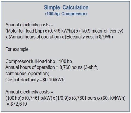
This equation assumes the electric motor driving the compressor is 90 percent efficient (the 90 in the 1/0.90 factor). Newer energy-efficient motors generally have even higher efficiencies, which are typically shown on the motor nameplate. If the system uses an older motor that has been rewound several times, or has a smaller motor, a somewhat lower percent efficiency (or the motor nameplate efficiency rating) should be used. For a more accurate analysis, add the horsepower ratings for the parasitic loads from any auxiliary motors such as cooling fans to the compressor motor rating.
It should be noted that the common practice in the industry is to apply motors having a 15 percent continuous service factor and to use about two-thirds of this service factor. This means that a motor having a nominal nameplate rating of 100 hp may, in fact, be loaded to 110 bhp at compressor full capacity and pressure. This may not be expressed in the manufacturer’s sales literature, so engineering data sheets or a published CAGI sheet for the specific compressor should be consulted. If the motor is running into the service factor (some as high as 30 percent), the higher horsepower estimate should be used instead of the nameplate horsepower rating.
A Calculation with Measurements. A more accurate way to determine electricity consumption and costs involves taking electrical measurements. The best option is to measure the kW directly; if this is not an option estimation can be done by measuring both full-load amps and volts. Motor full-load bhp and efficiency are not required for this calculation, although full-load power factor, which can be obtained from the motor nameplate or manufacturer’s data, is required. The calculation measures voltage and full-load amps, converts to full-load kW, and then multiplies by hours of operation and electricity costs. This calculation captures the lower power input due to lower than rated discharge pressure and accounts for ancillary loads. A calculation is shown below.
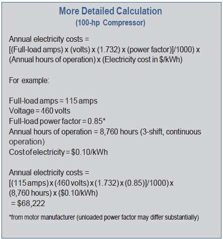
Part-Load Operation. If the compressed air system operates below full-load at times, and has a good control system, electricity costs will be less than if the compressor ran at full-load during all hours of operation. Estimate the percentage of time the compressor is running at full-load, and add the percentage as another multiplier in the equation shown previously. Compressor hour meters are a good source for this information. Repeat the calculation for the percentage of time the compressor is running unloaded (or at part- load) and include a factor to compensate for the reduced load on the motor (0.20 to 0.30 is a good estimate for fully unloaded operation for rotary screw compressors and 0.10 to 0.15 for reciprocating compressors—0.30 is used in the equation in the next text box). Add the two results for total energy costs.
For a more accurate calculation of energy costs for compressors running at part-load, create a number of “tiers” with the percentage of time running at different percentages of load. Manufacturers’ data on energy consumption for the different percentages of load will be needed.
The text box below shows an example calculation taking into account unloaded operation.
Remember, the calculations shown will only provide a good estimate of energy consumption, not an exact number.
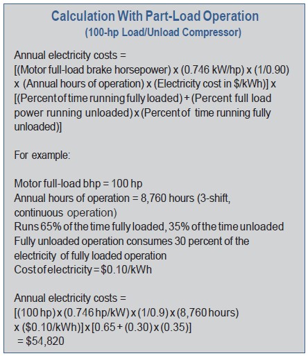
Energy and Demand Charges—Understanding Your Electricity Bill. The calculations shown previously use electricity rates stated in terms of $/kWh. Electric utilities bill industrial customers using more complicated rate structures that typically include both energy ($/kWh) and demand charges ($/kW), and may have different rates depending on the level of consumption ,time of day or seasons. Demand charges are based on the peak demand for a given month or season and can have significant impacts on electricity costs for some customers. When the economic impacts of efficiency measures are calculated, the actual marginal cost of the electricity needs to be considered, taking into account energy and demand charges, seasonal rates, and different rates for different levels of consumption.
Pressure and Electricity Cost. High-pressure air is more expensive to produce and deliver than low-pressure air. A rule of thumb for systems in the 100 psig range is: for every 2 psi increase in discharge pressure, energy consumption will increase by approximately 1 percent at full output flow (this may differ for centrifugal and two-stage, lubricant-injected, rotary screw compressors).
There is also another penalty for higher-than-needed pressure. Raising the compressor discharge pressure increases the demand of every unregulated usage, including leaks, open blowing, etc. Although it varies by plant, unregulated usage is commonly as high as 30 to 50 percent of air demand. For systems in the 100 psig range with 30 to 50 percent unregulated usage, a 2 psi increase in header pressure will increase energy consumption by about another 0.6 to 1.0 percent because of the additional unregulated air being consumed. The combined effect results in a total increase in energy consumption of about 1.6 to 2 percent for every 2 psi increase in discharge pressure for a system in the 100 psig range with 30 to 50 percent unregulated usage.
Savings from Performance Improvements. Because of the relatively low initial cost of the compressor when compared to lifetime electricity expenses, users should utilize life-cycle cost analysis when making decisions about compressed air systems. In addition, a highly efficient compressed air system is not merely a system with an energy-efficient motor or efficient compressor design. Overall system efficiency is the key to maximum cost savings. Too often users are only concerned with initial cost and accept the lowest bid on a compressed air system, ignoring system efficiency.
Thorough analysis and design will be required to obtain an efficient system. Many compressed air system users neglect these areas, thinking they are saving money, but end up spending much more in energy and maintenance costs.
Following the steps outlined in this course can lead to substantial energy savings for most compressed air systems. A system that has undergone numerous modifications and has only been maintained enough to keep it running can frequently achieve energy savings of 20 to 50 percent or more. For the 100-hp system described previously, this represents annual savings of $14,000 to $36,000. Larger systems will have correspondingly greater energy savings.
Too many decisions regarding compressed air systems are made on a first-cost basis, or with an “if it ain’t broke, don’t fix it” attitude. To achieve optimum compressed air system economics, compressed air system users should select equipment based on life- cycle economics, properly size components, operate equipment at the lowest possible pressure, turn off unneeded compressors, use appropriate control and storage strategies, and operate and maintain the equipment for peak performance.
Selling Projects to Management
Once you have defined your project and potential benefits and are ready to start work, what do you do next? If you are in the same situation as most plant engineering personnel, you need to request funding for the project from your management. Few individuals have the ability to make a major expenditure of funds without approval. All of the work done to create a block diagram, perform baselining, locate opportunities to save money, and organize a plan of action to reduce costs could be a waste of time if sufficient funding cannot be obtained from management to implement the change. Factors to consider securing funding will be discussed. Topics will be covered in general, rather than specifics, since each firm potentially requires a different approval process.
Financial management in any firm is focused on maximizing profit in that firm’s or that plant’s operation. Any money spent to improve a process or system in the plant is an expenditure that erodes the short-term profitability of that operation. This does not mean that management is opposed to spending money. It does mean that management will select to spend funds on projects that will increase profitability within a period of time that they set. If you offer suggestions or recommendations for a project that will save more money than it costs, you will get attention from your management. For example, if you have a project in mind that will cost $100,000, and it will decrease energy consumption by $125,000 per year, you are helping to improve profitability.
The easiest way to look at a project is annual savings and simple payback. Simple payback is simply the cost of the project divided by the projected annual savings. Let’s look at this concept by using two examples.
Example 1
Cost of the project: $100,000
Projected annual savings: $125,000 per year
Payback period: 9.6 months (100,000/125,000 x 12)
Example 2
Cost of the project: $100,000
Projected annual savings: $10,000 per year
Payback period: 120 months (100,000/10,000 x 12)
Note that annual savings could include reduced maintenance costs due to new upgraded equipment or additional annual savings due to reduced production losses as a result of poor compressed air system reliability.
Available utility incentives may be available that could reduce capital costs and project paybacks for qualifying energy efficiency measures. To search for these opportunities see the DSIRE database at www.dsireusa.org.
These simple calculations demonstrate two ways to measure the projected return of the cost of an improvement, annual savings, and simple payback period. These are usually used for smaller expenditures or to determine if the project is feasible. In general, projects with short paybacks (such as Example 1 above) can easily be approved.
Your financial management team will use the financial data that you submit to calculate other financial views of the expense. They may calculate the projected savings based on the net present value of the investment. Similarly, they may calculate the internal rate of return on the investment in a project. We will not go into discussion of these financial calculations or tools, since each firm has a different view and different requirements. If you have a project that meets simple payback criteria, work with your financial management to determine the methodology and expected results that the firm utilizes.
If your proposed project passes one of the simple tests, read on. If not, go back and look for other opportunities to save money.
You are now to the point that you have determined that your project will add to the operation’s profitability, at least in simple terms. What do you do next? You will most likely want to create a written presentation to your management asking for the approval to spend the money you need. It must be concise, outline specific actions to be taken, list the expected return or cost saving, and provide documentation to support the conclusions you made.
Many firms have a set format to use in a Capital Expenditure Request, to answer questions and supply information. If your company uses this method, your job is easier. Simply complete the form, attach the requested information, and send it for approval. You would be wise to have additional information and possibly a PowerPoint presentation. This will include all of the information in the Expenditure Request, plus other information, such as photos and excerpts from articles and publications. If your firm does not use a standard format, you will have to create your written presentation from scratch.
Creating your own presentation/request can be done quite simply if you think and act logically. It most likely will include the following.
- An “executive overview” that states the problem, the actions to be taken, the cost of the project, and the projected return. All of this should fit on one page of paper.
- Detailed information on current operating data and costs. This is where you use your baseline information. You will want to describe the methodology that you used to establish your baseline.
- A detailed list of the actions you plan to take, the equipment you need to buy, and a detailed cost summary. Make sure you include any internal costs for engineering, project management, and down- time. When possible, provide vendor quotes to back up your cost data.
- A detailed summary of the projected savings. What will change in operating cost, how did you calculate it, and what you considered. The presentation needs to be based on facts, and with full calculations to support the projected savings.
- A statement of risks that outlines what may not go exactly per the plan, and the contingencies you have included to quickly remove barriers that may affect the project as it progresses.
- A time schedule listing the start and end date of all actions.
- Photos, diagrams, and drawings to demonstrate the current state of operation, and what the end product will look like upon completion.
- A statement of results verification. In this section, you will outline the process and procedure that you will use to measure and document the actual cost savings.
- A list of references to articles, books, or presentations that support the action that you plan to take. Case studies of similar actions that achieved the planned results can be very useful.
- A summary, which will include a request for action by your management.
- A copy of the appropriate approval form that is fully completed except for management signatures.
- This documentation should be high-quality and use color copies when and where appropriate, and should be bound per the normal system used by your firm. Anything less than first class will not get the first-class reply, which is the approval for the project.
- Depending on your firm and the budget of the project, you may want to have a formal PowerPoint presentation if your management requests that.
- Finally, maintain complete and detailed records on any action related to the project and plan to keep them for a number of years after completion of the project. Documentation of project results is important.
Energy Management Systems
Facilities that seek to maintain low energy consumption may implement energy management systems (EnMS) such as ISO 50001. ISO 50001 provides organizations with an internationally recognized framework for implementing an energy management system (EnMS). The standard addresses the following:
- Energy use and consumption
- Measurement, documentation, and reporting of energy use and consumption
- Design and procurement practices for energy-using equipment, systems, and processes
- All variables affecting energy performance that can be monitored and influenced by the organization
An EnMS helps an organization internalize the policies, procedures, and tools to systematically track, analyze, and improve energy efficiency. It considers maintenance practices, operational controls, and the design and procurement of renovated, modified, and new equipment, systems, processes, and facilities. With ISO 50001, energy management is integrated into normal business processes involving multiple types of employees across the organization.
ISO 50001 is based on the Plan-Do-Check-Act structure to continual improvement held in common with the ISO 9001 (quality management), ISO 14001 (environmental management), and other management systems. ISO 50001 is designed to be compatible with these management systems.
As part of an EnMS the compressed air system may be identified as a significant energy use (SEU) and subject to continuous monitoring. As part of this monitoring energy performance indicators (EnPIs) will be compared against an energy baseline (EnB) to ensure the compressed air system energy performance is maintained at expected levels.