Chapter 1: Background
Purpose.
The purpose of this course is to familiarize engineers with electrical system grounding and bonding issues associated with solidly grounded systems under 600V. This course can serve as an introduction to grounding and bonding for engineers with little or no professional electrical design experience. The course also presents practical, but not idely known, grounding and bonding application information that will benefit even the most seasoned electrical design professional.
Why take time to study grounding and bonding?
It is a popular and incorrect belief held by many people in the electrical professions that grounding a metal object (by connecting it directly to earth)
will assist in removing dangerous voltage caused by a line to ground fault. Grounding an object does nothing to remove a dangerous voltage or reduce touch or step voltages that are responsible for several deaths each year.
Improper grounding and bonding are a common cause of electrical accidents.
Effective grounding plays an important role in the proper operation of sensitive electronic equipment.
“Better than 80% of all electronic system failures that are attributed to power anomalies are actually the result of electrical wiring or grounding errors or are generated by other loads within the customer’s facility.” EPRI (Electric Power Research Institute)
“Of all the power and grounding problems affecting electronic equipment, almost 90% are caused by electrical power and grounding conditions inside the facility in which the equipment is used…More importantly, almost 75% of the power quality problems inside the facility relate to grounding, which makes it the single most important factor from a facility standpoint, in having reliable equipment operation.” Warren Lewis, ECM Magazine
The 2005 Edition of the National Electrical Code (NEC) included a complete revision to and renaming of Article 250 (formerly titled “Grounding”) that was, in the words of the editors of the NEC Handbook “one of the most significant changes to occur in the recent history of the Code”.
Basis and Resources.
The following resources serve as the primary basis of the information presented in this
course and will be referenced in the course material:
National Electrical Code (NEC) Article 250 – 2005 Edition
IEEE Standard 1100-1999 Recommended Practice for Powering and Grounding Sensitive Electronic Equipment
IEEE Standard 142-1982 Grounding of Industrial and Commercial Power Systems
AEMC Understanding Ground Resistance Testing (Workbook Edition 6.0)
For many engineers, contractors and technicians, the National Electrical Code and its Article 250 (Grounding and Bonding), are the sole basis of grounding system design and installation criteria.
Before beginning the course it is vital that we review the intent and limitations of the National Electrical Code (NEC) – to understand how the NEC should be applied.
Article 90.1 of the National Electrical Code sets forth its purpose and intentional limitations:
According to the NEC – Engineers designing and specifying grounding and bonding should not use the National Electrical Code (NEC) as a cook book.
The NEC is not a substitute for understanding of the theory behind the code requirements.
Chapter 2: Definitions from the National Electrical Code.
In order to understand grounding and bonding it is important to know the meanings of the words we will be using. Article 110 of the National Electrical Code provides definitions for the words we will use in this course. They are listed in order of importance, not necessarily alphabetical order.

Grounded Conductor. A system or circuit conductor that is intentionally grounded. This is also commonly referred to as the neutral conductor on a grounded Wye system.
Grounding Conductor. A conductor used to connect equipment or the grounded circuit of a wiring system to a grounding electrode or electrodes.
Grounding Conductor, Equipment. The conductor used to connect the non–currentcarrying metal parts of equipment, raceways, and other enclosures to the system grounded conductor, the grounding electrode conductor, or both, at the service equipment or at the source of a separately derived system. NEC Article 250.118 describes the different types of equipment grounding conductors. Proper sizing of equipment grounding conductors is found in 250.122 and Table 250.122.
Grounding Electrode. A device that establishes an electrical connection to the earth.
Grounding Electrode Conductor. The conductor used to connect the grounding electrode(s) to the equipment grounding conductor, to the grounded conductor, or to both, at the service, at each building or structure where supplied by a feeder(s) or branch circuit(s), or at the source of a separately derived system.
Bonding (Bonded). The permanent joining of metallic parts to form an electrically conductive path that ensures electrical continuity and the capacity to conduct safely any current likely to be imposed.
Bonding Jumper. A reliable conductor to ensure the required electrical conductivity between metal parts required to be electrically connected.

Bonding Jumper, Equipment. The connection between two or more portions of the equipment grounding conductor.
Bonding Jumper, Main. The connection between the grounded circuit conductor and the equipment grounding conductor at the service.

Bonding Jumper, System. The connection between the grounded circuit conductor and the equipment grounding conductor at a separately derived system.
Grounded. Connected to earth or to some conducting body that serves in place of the earth.
Effectively Grounded. Intentionally connected to earth through a ground connection or connections of sufficiently low impedance and having sufficient current-carrying capacity to prevent the buildup of voltages that may result in undue hazards to connected equipment or to persons.
Solidly Grounded. Connected to ground without inserting any resistor or impedance device.
Chapter 3: What are Grounding and Bonding
A common misconception is that grounding and bonding are the same topic. Though they are related, they are not the same. A goal of this course is to clarify each topic.
The 2005 edition of the National Electrical Code recognized this and changed the title of Article 250 (which was formerly title “Grounding”) to Grounding and Bonding to reinforce that grounding and bonding are two separate concepts but are not mutually exclusive and, in fact, are directly interrelated through the requirements of Article 250.
Bonding is the connection of two or more conductive objects to one another by means of a conductor such as a wire.
Grounding, also referred to as “earthing”, is a specific form of bonding wherein one or more conductive objects are connected to the ground by means of a conductor such as a wire or rod.
Proper grounding of objects (conductors) in the field will normally incorporate both bonds between objects and a specific bond to the earth (ground).
According to the National Electrical Code Article 250.4(A), the following are the General Requirements for Grounding and Bonding for Grounded Systems. In a Grounded System, the supply transformer secondary windings may be wye-configured with the common leg grounded or delta configured with a center tap grounded or corner grounded.
Let’s review, from the previous page, the general requirements presented in the National Electrical Code for grounding and bonding to better understand which requirements are addressed through grounding (earthing) and which are addressed through bonding techniques.
Requirements (1) and (2) are grounding issues – they specifically reference “connection to earth”.
Requirement (1) is system grounding or the intentional connection of a system conductor on a grounded system to earth. The stated purpose of this intentional connection to earth is to limit the voltage imposed by lightning, line surges, or unintentional contact with higher-voltage lines and that will stabilize the voltage to earth during normal operation.
Requirement (2) is accomplished by bonding non-current carrying metal objects to the equipment grounding conductor which is bonded to the grounding electrode conductor at the service entrance and on the load side of each separately derived system.
Requirements (3), (4), and (5) are bonding issues. By bonding all metal items likely to become energized in the event of a fault (and by providing an equipment grounding conductor bonded to these items and to the source), an effective ground current path is provided facilitating the operation of over current protective devices. Simply put – the fault current path must be of sufficiently low resistance to allow fault current of sufficiently high magnitude to cause the protective device upstream to trip. Bonding also helps assure personnel safety, so that someone touching two pieces of equipment at the same time does not receive a shock by becoming the path of equalization if they happen to be at different potentials. For the same reason that bonding protects people, it protects equipment, by reducing current flow on power and data conductors between pieces of equipment at different potentials.
It is important to understand the difference between bonding and grounding (earthing). Keep in mind that earth (soil) is a poor conductor and should never be relied on as part of the ground fault current return path – that is the path intended to clear a fault. The reason that earth/soil should never be relied upon as part of the ground fault return path is due to its high resistance.
The resistance of earth is on the order of one billion times that of copper (according to IEEE standard 142 Section 2.2.8) and will only allow a few amperes (1-10) back to the source.
The Institute of Electrical and Electronics Engineers Standard 142 states “The most elaborate grounding system that can be designed may prove to be inadequate unless the connection of the system to the earth is adequate and has a low resistance. It follows, therefore, that the earth connection is one of the most important parts of the whole grounding system. It is also the most difficult part to design and to obtain… For small substations and industrial plants in general, a resistance of less than 5 ohms should be obtained if practicable.”
However, from a practical standpoint, a grounding electrode, no matter how low its resistance, can not be depended upon to clear a ground fault. If equipment is effectively grounded and bonded, then a path of low impedance (not through the grounding electrode to earth and through the earth back to the source) must be provided to facilitate the operation of the overcurrent devices in the circuit. While the lowest practical resistance of a grounding electrode is desirable and will better limit the potential of equipment frames above ground, it is more important to provide a low-impedance path to clear a fault promptly to ensure safety. To obtain the lowest practical impedance, the equipment grounding circuit must be connected to the grounded conductor within the service equipment.
Neither grounding (earthing) nor the grounding electrode system helps clear electrical faults. It is the bonding of the metal objects to the equipment grounding conductor back to the source that provides the path of sufficiently low impedance to allow overcurrent protective devices to operate and clear faults. If the ground fault path relies on the earth there will not be enough fault current (due to the high impedance) to trip the protective
device.
Remember Ohm’s Law, V = I x R? Consider the following example. A 120 Volt phase conductor is intentionally connected directly to the ground (if a live, bare wire were terminated to a ground rod in the dirt) and the ground rod has 25 ohms resistance back to the grounded power source (transformer). This scenario would yield just less than 5 Amperes (4.8A) of ground fault current. This intentional connection to earth would not yield enough fault current to trip even a 20A circuit breaker since a 20A circuit breaker can carry 16 Amperes continuously.
The same high impedance of the earth that limits the fault current to levels less than what is required to open protective devices will create dangerous step or touch voltages in the vicinity of the ground rod that can be deadly. Several people have died in recent years from this very condition – where street lighting poles were grounded (earthed) with ground rods but had no equipment grounding conductors to serve as an effective fault current path back to the power source.
Chapter 4: Factors Influencing Resistance of Grounding (Earthing) Systems
Let’s explore the factors that influence the resistance of grounding electrode (let’s use rods for discussion purposes) systems.
Resistance of the electrode (there’s a difference of a just few milli-ohms between different commonly used materials and sizes – IEEE Std 142-1982). The resistance of the electrode is a function of the material of the rod and the surface area of the rod. The surface area of the rod is a function of the rod diameter.
The rod to soil surface area (not a significant factor – typically only a fraction of an ohm – if the rod is driven in compacted soil and is not loose – IEEE Std 142-1982) Differences in ground rod sizes and materials make little appreciable difference in the resistance of the electrode (rod material does, however, play a role in the life expectancy of a rod).
The contact resistance between the rod and the surrounding soil. If the rod is driven into compacted soil then the resistance between the rod and the surrounding soil is not a significant factor (this is discussed in further detail in the section on deep driven ground rods).
The resistance of the soil surrounding the electrode (the biggest factor). In a properly installed grounding electrode system, soil resistance is the key factor that determines what the resistance of a grounding electrode will be, and to what depth a rod must be driven to obtain low ground resistance.
The resistivity of soils varies with the depth from the surface, the type of concentration of soluble chemicals (minerals and dissolved salts) in the soil, the moisture content and the soil temperature. In other words, the resistivity is determined by the electrolyte in the soil. Resistance of a 5/8” ground rod for typical soil types from IEEE 142-1982 are presented below:

Here are a few surprising facts:
According to this IEEE 142-1992 table, a 10’ ground rod driven in two of the four soil type categories did not provide, on the average, a resistance of 25 ohms or less! This is a common experience in many areas with sandy soil.
The presence of surface water does not necessarily indicate low resistivity (IEEE Std 142- 1982).
A recent project vividly illustrates the truth of this statement. The soil at a Water Reclamation Facility was always wet. Electrical engineers investigating grounding problems at the site naively thought that the constant presence of water (due to a high water table) would guarantee low soil resistivity and that individual ground rods or, possibly, paralleled ground rods would be sufficient to produce a low resistance ground (earth connection). However, the contrary was true. Further investigation revealed that the high water table was associated with a subsurface water flow. There was literally a river flowing through the site that was part of area’s hydrology. The soil was extremely sandy.
Over time, whatever soluble minerals that existed had been dissolved and carried away with the slow flowing water leaving sand and distilled water – both excellent insulators!
This discovery radically changed the focus of the site grounding investigation and resultant corrective action – leading the engineers to consider the stratification of soil.
Conventional grounding techniques that have been taught for the past forty years by grounding and grounding testing manufacturers are based on an assumed homogenous soil condition. Conventional techniques spawned rules of thumb that became accepted by many
engineers as standard practices. One such practice was that both doubling the depth of a ground rod and installing two parallel ground rods were equally effective techniques to lower the rod(s) resistance to earth. These rules of thumb pre-supposed that soil is homogeneous – that the soil remains the same type and resistivity as you go deeper. In practice, many areas have stratified soil rather than homogeneous soil.
As responsible engineers, we need be mindful that the practice of using parallel ground rods, sometimes connected in a delta configuration, that has been developed using techniques that assume homogeneous soil conditions may not be the best practice for a stratified soil condition.
We’ll explore this in more detail in the next section.
Chapter 5: What does the National Electrical Code Require? What does it allow?
What can serve as a grounding electrode?
Remember – the grounding electrode is the means of accomplishing two of the five grounding and bonding requirements listed in the National Electrical Code.
(1) Electrical System Grounding Electrical systems that are grounded shall be connected to earth in a manner that will limit the voltage imposed by lightning, line surges, or unintentional contact with higher-voltage lines and that will stabilize the voltage to earth during normal operation.
(2) Grounding of Electrical Equipment Non–current-carrying conductive materials enclosing electrical conductors or equipment, or forming part of such equipment, shall be connected to earth so as to limit the voltage to ground on these materials.
According to the National Electrical Code, the following can be used as grounding electrodes and if more than one is present they must be bonded together:
Underground metal water pipe (NEC 250.52 (A)(1))
Metal frame of the structure (NEC 250.52 (A)(2))
Concrete encased grounding electrode (a.k.a. UFER ground) (NEC 250.52 (A)(3))
Ground ring (NEC 250.52 (A)(4))
Ground rod (NEC 250.52 (A)(5))
Grounding plates (NEC 250.52 (A)(6))
The National Electrical Code details specific installation requirements for each type of electrode.
Two or more grounding electrodes that are effectively bonded together shall be considered as a single grounding electrode system.
Let’s consider the various locations where Grounding (meaning an intentional bond or connection to earthing system) is required. The National Electrical Code requires the following:
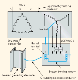
Service Entrance – NEC Article 250.24 (A) requires that a premises wiring system supplied by a grounded AC service shall have a grounding electrode conductor connected to the grounded service conductor (also referred to as a neutral conductor). Article 250.24 (A) (1) requires that the connection shall be made at any accessible point from the load end of the service drop or service lateral to and including the terminal or bus to which the grounded conductor (neutral) is connected at the service disconnecting means. This translates to one of three locations as shown below,

Separately derived systems – Refer to section VI for a discussion of separately derived system grounding.
Metal Water and other Metal Piping likely to become energized – 250.104 (A) and (B) requires that the metal water piping system shall be bonded to the earthing system at any one of the following locations: service equipment enclosure, grounded conductor at the service, the grounding electrode conductor or to the grounding electrodes. While metal water piping must be bonded to earth, other metal piping systems are only required to be
bonded to earth (grounded) if it is likely to become energized – that is where mechanical piping and electrical connections exist within equipment (i.e. gas appliances).
Structural Metal – 250.104 (C) requires exposed structural metal that is interconnected to form a metal building frame and is not intentionally grounded and is likely to become energized shall be bonded to ground at either the service equipment enclosure, grounded conductor at the service, the grounding electrode conductor or to the grounding electrodes.
Where an Alternating Current (AC) system is connected to a grounding electrode in or at a building or structure, the same electrode shall be used to ground conductor enclosures and equipment in or on that building or structure. Where separate services, feeders, or branch circuits supply a building and are required to be connected to a grounding electrode(s), the same grounding electrode(s) shall be used. This is to ensure that all metal objects in a structure reference the same ground (earth) potential.
What resistance to earth is required? Allowed?
If you were asked “How many Ohms resistance to earth does the National Electrical Code (NEC) require for a system ground?” What would you say? A) 25 ohms? B) 10 ohms? C) 100 ohms? Or D) Would you say that the NEC doesn’t specify a minimum requirement?
If you answered D) you would be correct! As hard is that is to believe, the National Electrical Code does not have a stated minimum resistance to earth for system grounds.
Let’s look at NEC Article 250-56

Note that the NEC says where “A single electrode…”. Also note that it does not call for retesting and driving additional rods or additional lengths of rods until 25 ohms or less is achieved. This article of the NEC allows a contractor to drive two rods, spaced 6 feet apart, perform no ground testing and call it a day!
Many areas have stratified (meaning layered), sandy soil. Most pure sand is quartz, silicon dioxide (SiO2). Silicon dioxide is a high-quality electrical insulator which is commonly used as a barrier material during impurity implants or diffusion, for electrical isolation of semiconductor devices, as a component in metal oxide semiconductor (MOS) transistors, or as an interlayer dielectric in multilevel metallization structures such as multi-chip
modules. Sand is a good insulator; it is NOT a good grounding material.
In order to get out of stratified sandy soil conditions one must drive ground rods deeper through the layer of sand (however deep that is) and into a more conductive soil.
Placing multiple parallel rods in sandy soil is of little to no value if a low resistance connection to earth is desired – you must get below the layer of sand.
Chapter 6: Sizing Equipment Grounding and Grounding Electrode Conductors
The National Electrical Code contains two tables that relate to the size of grounding and bonding.
Table 250.66 Grounding Conductor for Alternating Current Systems
Table 250.122 Minimum Size Equipment Grounding Conductors for Grounding Raceway and Equipment.

Notes:
1. Where multiple sets of service-entrance conductors are used as permitted in 230.40, Exception No. 2, the equivalent size of the largest service-entrance conductor shall be determined by the largest sum of the areas of the corresponding conductors of each set.
2. Where there are no service-entrance conductors, the grounding electrode conductor size shall be determined by the equivalent size of the largest service-entrance conductor required for the load to be served.

Note:
Where necessary to comply with 250.4(A)(5) or (B)(4), the equipment grounding conductor shall be sized larger than given in this table.
*See installation restrictions in 250.120.
The origin of these tables was an IEEE committee report “A Guide to Safety in AC Substation Grounding”. The committee report discussed the validity of grounding conductor sizes specified in the tables – based on a typical conductor length of 100’ and the voltage drop over the conductor based on this 100’ length. [A Guide to the National Electrical Code – Gregory Bierals – Electrical Design Institute]. For lengths over 100’ the “minimum size” indicated by the table may not be adequate to clear a fault or conduct the fault current subjected to it.
From a practical standpoint, grounding electrode conductors are rarely designed to be in excess of 100’ length and Table 250.66 can be relied up almost without exception.
Equipment grounding conductors, on the other hand, are often longer than 100’, that is whenever the length of the branch circuit or feeder the equipment grounding conductor they are installed with are longer than 100’. In these situations, the minimum equipment grounding conductor indicated by Table 250.122 will not be adequate to carry and or clear anticipated fault currents.
Experienced electrical facility engineers and design professionals are familiar with the need to increase conductor sizes for long branch circuit and feeder conductors to address and mitigate voltage drop issues. Article 250.122 (B) directs that the equipment grounding conductor shall also be increased.
Equipment grounding conductors on the load side of the service disconnecting means and overcurrent devices are sized based on the size of the feeder or branch-circuit overcurrent devices ahead of them.
Where the ungrounded circuit conductors (live, line conductors) are increased in size to compensate for voltage drop or for any other reason related to proper circuit operation, the equipment grounding conductors must be increased proportionately.
Example:
A 240-volt, single-phase, 250-ampere load is supplied from a 300-ampere breaker located in a panelboard 500 ft away. The “normal” circuit (not upsized to limit voltage drop) would consist of 250-kcmil copper conductors with a 4 AWG copper equipment grounding conductor. If the conductors were increased to 350 kcmil for voltage drop considerations, what is the minimum size for the equipment grounding conductor based on the proportional-increase requirement?
Solution
STEP 1.
Calculate the size ratio of the upsized conductors to the normal sized conductors:
![]()
STEP 2.
Calculate the cross-sectional area of the upsized equipment grounding conductor by multiplying the size ration times the cross sectional area of the standard size equipment grounding conductor taken from Table 250.122 for a 250A protective device (must use the next larger or 300A). Table 250.122 indicates that a number 4 AWG copper conductor is appropriate. According to Chapter 9, Table 8 of the National Electrical Code – Conductor
Properties (see page 21) a 4 AWG grounding conductor has a cross-sectional area of 41,740 circular mils.
Size Ratio x circular mils of the grounding conductor
1.4 x 41,740 circular mils = 58,436 circular mils
STEP 3.
Determine the size of the new equipment grounding conductor.
Again, referring to Chapter 9, Table 8, we find that 58,436 circular mils is larger than 3 AWG. The next larger size is 66,360 circular mils, which converts to a 2 AWG copper equipment grounding conductor.
For the scenario given, the normal equipment grounding conductor indicated by Table 250.122 for a 250A circuit would be a No. 4 AWG copper grounding conductor. In this case, the equipment grounding conductor needs to be increased to a No. 2 AWG copper grounding conductor in order to meet the requirements of NEC Article 250.122 (B). The intent of this requirement for upsizing is to provide a conductor that is adequately sized to carry and clear anticipated fault currents.

Chapter 7: Neutral-Ground bond-Where? Why?
The neutral and equipment grounding conductor are required by the National Electrical Code (NEC) to be bonded at the main service panel and the secondary side of a separately derived system (more on this below). Only one neutral to ground bond is permitted by the NEC to exist on each separately derived system. Improper, additional neutral – ground bonds are a relatively common problem that not only create shock hazards for operating personnel, but can also degrade the performance of electronic equipment. Improper neutral – ground bonds at receptacles can be detected using a wiring and grounding tester designed for that purpose.
A voltmeter can also be used to indicate if improper bonds exist at receptacles. A voltage measurement between neutral and ground at the outlets can indicate voltage ranging from a milli-volt to several volts under normal operating conditions and depending on loading, circuit length, etc. However a reading of 0 V can indicate the presence of a nearby neutral – ground bond. Excessive current on equipment grounds in distribution panels also indicates the possibility of a load-side neutral ground bond. Visual inspection of the neutral bus within panelboards is necessary to verify the location of these extra and improper bonds.
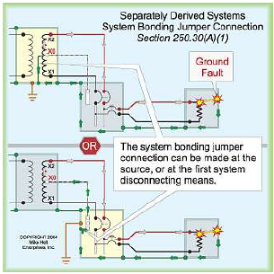
When more than one neutral – ground bond exists on a separately derived system – it results in the neutral and ground conductors being intentionally connected (or bonded) at two locations. This creates a parallel connection in which the neutral current is divided with a portion returning on the neutral and the rest returning to the source via the equipment grounding path according to ohms law (current will divided proportionally to take the path of least resistance with the voltage drop along each parallel path being the same). The figure below presents the two options to prevent objectionable current from flowing in the grounding (and bonding) system.
Separately derived systems are systems that have no direct connection between the output supply conductors and the input supply conductors. These are transformers with no direct connection between the primary system neutral and secondary neutral, only UPS systems that incorporate an isolation transformers thereby deriving a new neutral system conductor (note – all UPS Systems are not separately derived systems), and engine generators sets that connect to the building wiring system via a 4 pole transfer switch are separately derived systems because they have a separate neutral that has no direct connection to the utility neutral (due to the 4th pole of the transfer switch). Engine – generator sets applied with 3 pole transfer systems have a direct connection to the utility system neutral and are not separately derived systems and can not have a neutral ground bond at the engine generator set. [IEEE Std 1100-1999]
Chapter 8: Isolated Grounds
There is much discussion of isolated or dedicated grounds related to sensitive electronic equipment. National Electrical Code Article 250.96 (B) permits electronic equipment to be isolated from the raceway in the same way cord and plug-connected equipment is isolated from raceway.
FPN (FINE PRINT NOTE): Use of an isolated equipment grounding conductor does not relieve the requirement for grounding the raceway system.
The key to this method of grounding electronic equipment is to always ensure that the insulated grounding conductor, regardless of where it terminates in the distribution system, is connected in a manner that creates an effective path for ground fault current (through bonding) as required by NEC 250.4(A)(5).
While the use of isolated equipment grounding conductors may be useful in reducing electromagnetic interference, it is vital that the requirement for Isolated Ground NOT result in a connection to ground that is isolated, insulated or otherwise not connected to the building grounding electrode system. Such an isolated ground rod (connection to earth) would violate NEC 250.50.
The reason that an isolated ground rod (that is one that is not bonded to the other grounded or earthed electrodes) is prohibited and that the NEC requires that separate grounding electrodes be bonded together is to reduce the differences of potential between them due to lightning or accidental contact with power lines. Lightning protection systems, communications, radio and TV, and CATV system grounds must ALL be bonded together to minimize the potential differences between the systems. Lack of interconnection (or bonding) of all grounding components can result in a severe shock and fire hazard.


The following are examples of real cases in which individual grounds or items that should be grounded (earthed) were isolated from each other (not bonded together):
A woman noticed a “tingling” of electricity when she showered. An investigation revealed that an electrical voltage was present between the shower drain and the shower knobs. The fact that the woman was in her bare feet with wet hands (as people often are in showers!) contributed to the sensitivity of her noticing the voltage difference. The cause of the problem was found to be stray voltages produced by an overhead distribution line. The voltage difference was between the well and the septic system. The solution was to bond the drain and water pipes together.
A business owner was complaining regarding continual computer modem and computer failures. The utility company found that the failures occurred coincidentally with power disturbances (ground faults) on one of the main feeders serving the site. An investigation showed that the telephone, water and power grounds were electrically isolated (not connected to each other). Proper bonding (interconnecting) of the systems eliminated further problems with that customer.
[Examples are cited from “The Grounding of Power Systems: A Practical View Point” Paper Number PCIC-2002-xx John P. Nelson IEEE Fellow]
Chapter 9: Grounds Rods, Cladding and Ufers, oh my…
The term “Ufer” grounding is named after a consultant working for the US Army during World War II. The technique Mr. Ufer came up with was necessary because the site needing grounding had no underground water table and little rainfall. The desert site was a series of bomb storage vaults in the area of Flagstaff, Arizona.
The principle of the Ufer ground is simple. It is very effective and inexpensive to install during new construction. The Ufer ground takes advantage of concrete’s agorascopic properties. Concrete absorbs moisture quickly and loses moisture very slowly. The mineral properties of concrete (lime and others) and their inherent pH means concrete has a supply of ions to conduct current. The soil around concrete becomes “doped” by the concrete. As a result, the pH of the soil rises and reduces what would normally be 1000 ohm meter soil conditions (hard to get a good ground). The moisture present, (concrete gives up moisture very slowly), in combination with the “doped” soil, make a good conductor for electrical energy or lightning currents.
The effect is much the same as that of chemically treating soil around an electrode. The authors of a 1969 IEEE paper concluded following extensive tests of such an electrode system: “. . . the reinforcing bar networks of … concrete footings provide acceptably low grounding resistance, with fault and surge current capability suitable for all types of structure and circuit grounding. . . . Not the least of the advantages of the rebar system are its ready availability and low cost.” [Fagan & Lee, “The Use of Concrete Enclosed Reinforcing Rods as Grounding Electrodes,” 1969 Petroleum & Chemical Industry Conference.]
Ufer techniques are used in building footers, concrete floors, radio and television towers, tower guy wire anchors, light poles, etc. Copper wire does not function well as a “Ufer” ground due to the pH factor of concrete (+7pH is common). The use of steel reinforcement as a “Ufer” ground works well and concrete does not chip or flake as has been found with copper. The use of copper wire tied to the reinforcement rods that are outside the concrete shows none of these problems.
The minimum rebar necessary to avoid concrete problems depends on:
1. The type of concrete, its content, density, resistivity, pH factor, etc.
2. Amount of concrete surface area in contact with the soil.
3. Soil resistivity and ground water content.
4. Size and length of the reinforcement rod, wire, or plate.
5. Size of the lighting strike current.
The following chart shows the conductivity of lightning current per foot of Rebar (reinforcement rod). Only the outside Rebar can be counted. Rebar in the center of the footer or foundation does not count in this calculation. In a trench footer only the rebar in the sides and bottom of the footer can be counted.

Mr. Ufer did not know what he had found until he experimented with various lengths of wire in concrete. Today’s informed engineer benefits from Mr. Ufer’s discovery and will tie in the bars of steel reinforcement in a building or other foundation to the building electrical ground. When bonded to the electrical ground, building steel, etc., the buildings reinforced floor and foundation become part of the building grounding system. The result is a much improved grounding system with a very low overall resistance to earth reference.
If Ufer grounding alone was enough, the manufacturers of ground rods would go out of business. But a Ufer ground alone it is not adequate. Few buildings, even those under construction today are built to take advantage of the Ufer ground. It is common to see the use of “Ufer grounding” in military installations, computer rooms, and other structures with very specific grounding specifications. It is not common in most industrial plants, office buildings and homes. More common today is grounding to meet the minimum national and local electrical codes. This will involve one or more driven ground rods connected (bonded) to the neutral wire of the electrical service entrance.
In 2005, the NEC was revised to clearly require the inclusion of a UFER or concreteencased electrode, (now in 250.52(A)(3)), in the grounding electrode system for buildings or structures having a concrete footing or foundation with not less than 20 ft of surface area in direct contact with the earth. This requirement applies to all buildings and structures with a foundation and/or footing having 20 ft or more of 1/ 2 in. or greater electrically conductive reinforcing steel or 20 ft or more of bare copper not smaller than 4 AWG.
Ground rods come in many forms, but the most common used in electrical service grounding are galvanized steel ground rods. Please remember, the best day a ground rod will normally see (resistivity) is the day it is installed. Corrosion, glazing, etc., all are factors that lessen the effectiveness of ground rods.
Ground rods in general are divided into one of the following sizes; 1/2”, 5/8”, 3/4” and 1”. They come in steel with stainless, galvanized or copper cladding and can be solid stainless or mild (unclad) steel. They can be purchased in unthreaded or threaded sections that vary in length. The most common lengths are 8’ and 10’. Some will have a pointed end, others will be threaded and can be coupled together to form longer rods when driven.
The effectiveness of a 1” ground rod over the 1/2” ground rod is minimal when resistance readings are taken. The larger rods are chosen for more difficult soil conditions. Clay or rocky conditions often dictate the use of power drivers, similar to an impact driver used by mechanics when working on your automobile. They are typically electric or pneumatic. The power drivers when used with the heavy 1” ground rods will drive in most soils.
A 1” copper clad rod when compared to a 1/2” copper clad rod in the same soil conditions will yield about a 23% improvement is performance. The surface area of the 1/2” rod is 1.57 compared to the 1” rod at 3.14 (3.14 x .5 = 1.57 and 3.14 x 1 = 3.14). So, for double the surface area, you only get about a 23% improvement in performance.
The cladding of ground rods is to protect the steel from rusting. Most think the cladding, (copper on a steel rod) is for the increase in conductivity of the rod. It does aid in conduction, but the main purpose of the cladding is to keep the rod from rusting away.
Not all clad ground rods are the same and it is important the clad rod have a reasonably thick cladding. High quality industrial quality copper clad steel ground rods may cost a little more but they are worth the small extra cost.
When a ground rod is driven into rocky soil, it can scratch off the cladding and the rod will rust. Rust is not conductive when dry, in fact it is a good insulator. When it is wet it is still not as conductive as the copper on the rod. Soil pH can be tested and that should determine the type of rod used. In high pH soil conditions only high quality clad rods should be used. If the soil is extremely acidic, stainless rods are the best choice. One of the most popular ground rods is the galvanized (hot dipped zinc) steel ground rod.
This rod is used with copper and aluminum conductors to form the service entrance ground in most buildings and homes. This is a poor choice for ground resistivity over time. The joint between the ground rod and conductor are made above or below the surface of the ground and in most cases subject to constant moisture. Under the best conditions the joint between two dissimilar materials will result in corrosion and increased resistance over time.
When dissimilar materials are joined, electrolysis occurs. If Aluminum is used with copper that is not tinned the aluminum will pit to the copper leaving less surface area for contact and the connection could come loose and even allow arcing. Any sharp blow or impact could cause the connection to be broken. When installing in the soil it is not recommended tinned wire be used. Tin, lead, zinc and aluminum are all more anodic than copper and they will sacrifice (disappear) in the soil. When the connection is made above the surface of the soil in the electrical distribution panel tinned wire is acceptable.
Keep in mind that article 250.64 of the National Electrical Code indicates that aluminum or copper clad aluminum grounding conductors are not allowed to come in contact with soil or concrete and must be terminated at least 18” above finished grade when used outdoors.
Another treatment for joint corrosion problems is using a joint compound to prevent moisture bridging between the metals. The more popular compounds are copper or graphite particles imbedded in a grease compound. Using similar material is a better solution as even joint compounds can loose their effectiveness if not maintained but their use is preferable to a dry joint. Joint compounds work by imbedding particles into the metals to form a virgin junction of low resistance void of air when they are placed under pressure. The act of tightening the clamp on the conductor and rod provide this pressure.
The problem of dissimilar material is not found in copper clad steel rods. Of all the reasonably priced choices, the copper clad steel rod with a copper conductor is your best choice. If money were no object a gold conductor, and ground rod would be ideal, but hardly economically practical.
A driven rod, when compared to a back filled rod, is much better. The density of undisturbed soil is much higher than even compacted soil. The connection of the soil to the rod is the key to the rod’s performance.
One interesting aspect regarding grounding electrode conductors is their need for physical protection. If a steel conduit or sleeve is used to protect the grounding electrode conductor, then some means must be provided ton each end of the sleeve to make it continuous, electrically with the conductor. This can be accomplished by installing a bonding jumper on each end of the sleeve and terminating it to the sleeve and equipment and grounding electrode on each end. The reason that this method is important is that during heavy fault conditions the steel conduit sleeve produces a choke effect (the inductance of the sleeve sets up a magnetic field that opposes changes in current) and the impedance of the grounding system increase drastically. Because of this – it is a better idea to use appropriately rated (schedule 80 where subject to damage) non-metallic covering for physical protection whenever possible.
Installing ground rods is not difficult but proper procedures must be followed and the resulting rod(s) should be checked for performance.
Chapter 10: Deep Driven Ground Rod Considerations
Installing ground rods beyond 10 foot deep presents several problems. Sectional rods mus be used (typically 10-12 foot long) and coupled together to achieve the desired depth. The coupler is a larger diameter than the rod and therefore forms a hole bigger than the rod itself. This creates a coupler void limiting soil contact to the rod surface of the additional sections. Only the first section will maintain full rod to soil contact.
Manual driving of the rods with sledge hammers, pipe drivers, and other means cannot provide adequate force to penetrate hard soils. Mechanical or powered drivers are necessary for deep driven rods.
The rod material and coupler design must be able to withstand the force necessary to drive through hard subsoil.
Due to the extreme forces required to drive longer rods, screw type couplers mechanically fail. The threads get stripped causing poor rod to rod contact. A tapered spline/compression coupler has proven to be the most reliable coupler.
To maintain full rod to soil contact, a slurry mix of sodium bentonite (a naturally occurring clay) can be injected into the coupler void as the rods are installed. This provides a conductive material between the rod surface and soil over the depth of the rod. A typical 60 foot ground rod requires 2 to 5 gallons of bentonite.
There is a down side to driving longer, deeper rods in that the coupled rods can bend as they encounter denser soil. One project called for a contractor to couple and drive a 100’ ground rod in order to achieve 5 Ohm resistance in a stratified, sandy soil condition. As the contractor coupled and drove the fifth 10’section of rod, it was noticed that the “pointy end” of the ground rod was coming up under a car in the nearby parking lot. [Deep Earth Grounding versus Shallow Earth Grounding, Computer Power Corporation by Martin D. Conroy and Paul G. Richard – http://www.cpccorp.com/deep.htm]
Chapter 11: Maintenance Issues
The effective performance of ground rods is reduced by soil conditions, lightning currents, physical damage, corrosion, etc., and should be checked for resistance on a regular basis. Just because a ground was good last year it does not mean it is today.
Have it checked by the fall of potential testing method or clamp on method provided the installation is appropriate for ground resistance measurement using the clamp on technique (see next section for discussion of testing instruments and methods).
Chapter 12: Testing Methods
The measurement of ground resistances can only be accomplished with specially designed equipment. Most instruments use the fall of potential principal of alternating current (AC) circulating between an auxiliary electrode and the ground electrode under test. The reading is ohms and represents the resistance of the ground electrode to the surrounding earth. Several testing equipment manufacturers have recently introduced clamp-on ground resistance testers which will also be discussed.
Ground Resistance Testing Principle (Fall of Potential – 3 Point Measurement)
The potential difference between rods X and Y is measured by a voltmeter, and the current flow between rods X and Z is measured by an Ammeter (refer to figure 13)
By Ohm’s Law E = IR or R + E / I, then we may obtain the ground rod resistance R. If E = 20 V and I = 1 A then:
R = E / I = 20 / 1 = 20
It is not necessary to carry out all measurements when using a ground tester. The ground tester will measure directly be generating its own current and displaying the resistance of the ground electrode.

Position of Auxiliary Electrodes on Measurements
The goal in precisely measuring the resistance to ground is to place the auxiliary current electrode Z far enough from the ground electrode under test so that the auxiliary potential electrode Y will be outside of the effective resistance area of both the ground electrode and the auxiliary current electrode. The best way to find out if the auxiliary potential rod Y is outside the effective resistance areas is to move it between X and Z and to take a reading at each location. If the auxiliary potential rod Y is in an effective resistance area (or both if they overlap as in figure 14), by displacing it the readings taken will vary noticeably in value. Under these conditions, no exact value of the resistance to ground may be determined.
On the other hand, if the auxiliary potential rod Y is located outside of the effective resistance areas (figure X), as Y is moved back and forth the reading variation is minimal. The readings taken should be relatively close to each other, and are the best values for the resistance to ground X. the readings should be plotted to ensure they lie in a “plateau” region as shown in Figure 15. The region is often referred to as the “62% area”.


Measuring Resistance of Ground Electrodes (62% Method)
The 62% method has been adopted after graphical consideration and after actual test. It is the most accurate method but is limited by the fact that the ground tested is a single unit.
This method applies only when all three electrodes are in a straight line and the ground is a single electrode, pipe, or plate as in Figure 16.

Consider Figure 17, which shows the effective resistance areas (concentric shells) of ground electrode X and of the auxiliary current electrode Z. The resistance areas overlap. If readings were taken by moving the auxiliary potential electrode Y towards either X or Z, then reading differentials would be great and one could not obtain a reading within a reasonable band of tolerance. The sensitive areas overlap and act constantly to increase resistance as Y is moved away from X.

Now consider Figure 18, where the X and Z electrodes are sufficiently spaced so that the areas of effective resistance do not overlap. If we plot the resistance measured we find that the measurements level off when Y is placed at 62% of the distance from X to Z and that the readings on either side of the initial Y setting (62%) are most likely to be within the established tolerance band. This tolerance band is defined by the user and expressed as a
percent of the initial reading +/- 2%, +/-5%, +/-10% etc.

Auxiliary Electrode Spacing
No definite distance between X and Z can be given, since this distance is relative to the diameter of the rod tested, its length, the homogeneity of the soil tested, and particularly, the effective resistance areas. However, an approximate distance may be determined from the following chart which is given for homogenous soil and an electrode of 1” in diameter (for a diameter of ½” reduce the distance by 10%).

Clamp-on Ground Resistance Measurement
Unlike the Fall of Potential (three point) method which requires the ground rod or system under test be disconnected from the power system, this measurement method requires a connection between a rod under test to the line side utility’s connections to earth. As a result, the method offers the ability to measure the resistance without disconnecting the ground. It also offers the advantage of including the bonding to ground and overall grounding connection resistances.
Principle of Operation
Usually a common distribution line grounded system can be simulated as a simple basic circuit as shown in Figure 29 or and equivalent circuit shown in figure 30. If voltage E is applied to any measured grounding element Rx through a special transformer, a current I flows through the circuit, which can be represented by the following equation:

The gist of this is that a grounding electrode for a typical grounded electrical system is i parallel with ground rods and butt grounds at every transformer and pole that is on the line side of the service you are testing the ground for. All the upstream grounds in parallel become a very, very small parallel resistance in comparison to the resistance of the rod you are resting (Rx).
If Rx and R1, and R2…. are all about the same magnitude and n is a large number (such as 200) then Rx will be much less than

For example, if Rx, R1, R2, R3 etc…are all 10 Ohms and n = 200 then:

In this example, we can see that as long as the number of ground rods on the utility system is large (and the rod under test is connected to them), then the equivalent resistance of the line side rods (.05 Ohms) is negligible with respect to the ground resistance being measured (10 Ohms).
E / I = Rx is established. If I is detected with E kept constant, measured grounding element resistance can be obtained. Refer again to figures 29 and 30. Current is fed to a special transformer via a power amplifier via 1.7 kHz constant voltage oscillator. This current is detected by a detection CT. On the 1.7 kHz frequency signal is amplified by a filter amplifier. This occurs before analog to digital conversion and after synchronous rectification. It is then displayed on the Liquid Crystal Display.

The filter amplifier is used to cut off both earth current at commercial frequency and high frequency noise. Voltage is detected by coils wound around the injection CT which is then amplified, rectified and compared by a level comparator. If the clamp on CT is not closed properly and OPEN or OPEN jaw indication appears on the LCD.
While the accuracy of clamp on ground resistance testers is good for many scenarios but has it’s limitations. For example if line side grounding conditions are unknown (the premise for the clamp-on tester’s theory of operation relies on this) or if there are not a large number of line side grounds on the utility system (pole butt grounds) then a three point fall of potential test should be performed.
Before using and relying on data from any metering equipment make sure it has been calibrated and certified. If you don’t, the data that it provides may be worthless.
This discussion of Ground Resistance testing methods has been extracted from non copyrighted material from AEMC Instruments “Understanding Ground Resistance Testing” Workbook Edition 6.0.