Ch. 1 General
1.1 Purpose
The purpose of the Prescriptive Method for Structural Insulated Panels (SIPs) in Construction (Prescriptive Method) is to provide prescriptive requirements for the use of structural insulated panels (SIPs) in wall systems in the construction of residential structures. These provisions include definitions, span tables, material requirements, and other related information appropriate for use by home builders, design professionals, and building code officials.
1.2 Approach
The prescriptive requirements were developed by applying accepted engineering principles and supported with relevant structural test data. The provisions of the Prescriptive Method were also based on the Minimum Design Loads for Buildings and Other Structures (ASCE 7) [1], the International Building Code [2], and the International Residential Code [3].
1.3 Scope
The provisions of the Prescriptive Method apply to the construction of detached one- or two-family dwellings, townhouses, and other attached single-family dwellings and accessory structures in compliance with the general limitations to Table 1.1. SIP wall system construction in accordance with this Prescriptive Method shall be limited by the applicability limits set forth in Table 1.1. The limitations are intended to define an appropriate use of this document for most one- and two-family dwellings. Intermixing of these provisions with other construction materials, such as wood or steel framing, in a single structure shall be in accordance with the applicable building code requirements for that material and the applicability limits set forth in Table 1.1.
Engineering design shall be required for houses built in regions where the wind speed is greater than 130 mph (209 km/hr), regions along the immediate hurricane-prone coastline subjected to storm surge (i.e., beach front property), regions in Seismic Design Categories D0, D1 and D2, and regions in near-fault seismic hazard conditions (i.e., Seismic Design Category E) as defined by the provisions of ASCE 7.
Additional criteria as established by the local jurisdiction shall be considered and addressed for buildings constructed in accordance with the provisions of this document as limited by the provisions of this section.
Table 1.1
Applicability Limits
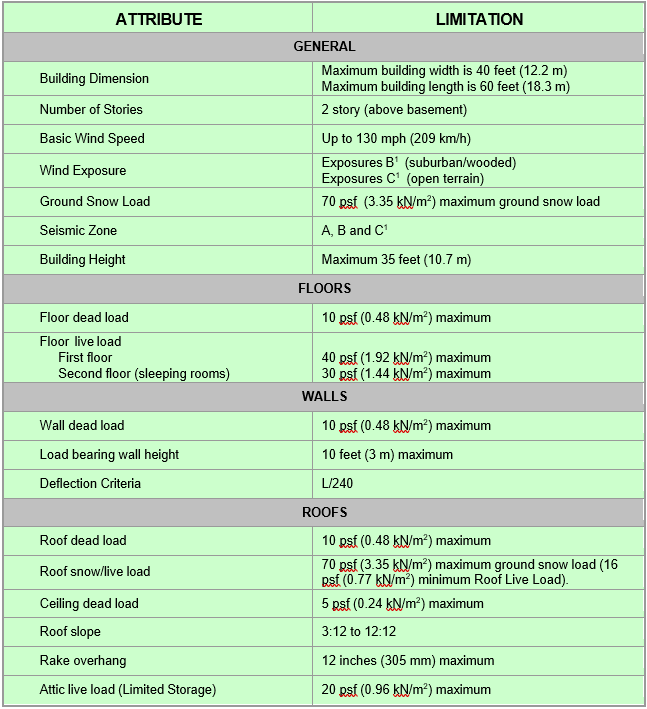
Table 1.1 Notes:
For SI: 1 inch = 25.4 mm, 1 psf = 0.0479 kN/m2, 1 mph = 1.61 km/hr = 0.447 m/sec, 1 foot = 0.3 m.
1 As defined by the provisions in ASCE 7.
1.4 Definitions
Accepted Engineering Practice: An engineering approach that conforms with accepted principles, tests, technical standards, and sound judgment.
Anchor Bolt: A bolt, headed or threaded, used to connect a structural member of different material to a concrete member.
Approved: Reference to approval by the building code authority having jurisdiction. Product testing or a rational design by a competent design professional is commonly accepted by the code body as grounds for approval.
Attic: The enclosed space between the ceiling joists of the top-most floor and the roof rafters of a building not intended for occupancy but sometimes used for storage.
Authority Having Jurisdiction: The organization, political subdivision, office, or individual charged with the responsibility of administering and enforcing the provisions of applicable building codes.
Axial Load: A force acting in line with a member’s longitudinal axis. Examples are the gravity loads carried by columns or wall panels.
Basement: That portion of a building, which is partly, or completely below grade and which may be used as habitable space.
Building: Any one- or two-family dwelling or portion thereof that is used for human habitation.
Building Height: The vertical distance between the average grade, as measured against the building foundation, to either the highest point of the roof beams (for flat-roofed buildings) or the mean height between the eaves and the roof peak for pitched roofs.
Building Length: The dimension of a building that is perpendicular to roof rafters, roof trusses, or floor joists (L).
Building Width: The dimension of a building that is parallel to roof rafters, roof trusses, floor joists, or roof SIPs (W).
Ceiling Joist: A horizontal structural framing member that supports ceiling components and which may be subject to attic loads.
Core: The lightweight middle section of the sandwich structural insulated panel composed of molded expanded polystyrene (EPS) insulation or alternative, which provides the link between the two facing shells.
Dead Load: Forces resulting from the weight of walls, partitions, framing, floors, ceilings, roofs, and all other permanent construction entering into, and becoming part of, a building.
Deflection: Elastic movement of a loaded structural member or assembly (i.e., beam or wall).
Design Professional: An individual licensed to practice their respective design profession as defined by the statutory requirements of the state in which the project is to be constructed.
Design (or Basic) Wind Speed: Related to winds that are expected to be exceeded once every 50 years at a given site (i.e., 50-year return period). Wind speeds in this document are given in units of miles per hour (mph) by 3-second gust measurements in accordance with ASCE 7 [1].
Dwelling: Any building that contains one or two dwelling units for living purposes.
Endwall: The exterior wall of a building which is perpendicular to the roof ridge and parallel to floor framing, roof rafters, or trusses. It is normally the shorter dimension of a rectangular building’s footprint.
Exposure Categories: Reflects the effect of the ground surface roughness on wind loads in accordance with ASCE 7 [1]. Exposure Category B includes urban and suburban areas or other terrain with numerous closely spaced obstructions having the size of single-family dwellings or larger. Exposure Category C includes open terrain with scattered obstructions having heights generally less than 30 ft (9.1 m) and shorelines in hurricane prone regions.
Facing: The wood structural panel facers that form the two outmost rigid layers of the structural insulated panel.
Floor Joist: A horizontal structural framing member that supports floor loads and superimposed vertical loads.
Foundation: The structural elements through which the loads of a structure, both vertical and lateral, are transmitted to the earth.
Foundation Wall: The structural element of a foundation that transmits the load of a structure to the earth; includes basement, stem, and crawlspace walls.
Grade: The finished ground level adjoining the building at all exterior walls.
Ground Snow Load: Measured load on the ground due to snow accumulation developed from a statistical analysis of weather records expected to be exceeded once every 50 years at a given site.
In-Line Framing: A framing method where all vertical and horizontal load carrying members are aligned.
Lateral Load: A horizontal force, created by wind or earthquake, acting on a structure or its components.
Lateral Support: A horizontal member providing stability to a column or wall across either of its smaller dimensions. (Lateral support can be applied to either of the minor dimensions of an axially-loaded member.)
Live Loads: Those loads produced by the use and occupancy of the building or other structure and do not include construction or environmental loads such as wind load, snow load, rain load, earthquake load, flood load or dead load.
Load Bearing Walls: Walls subject to loads that exceed the limits for non-load bearing walls.
Multiple Span: The span made by a continuous member having intermediate supports.
Non-Load Bearing Walls: Walls that are limited to a lateral (transverse) load of not more than 5 psf (240 Pa), a superimposed vertical load per member, exclusive of sheathing materials, of not more than 100 lb/ft (1460 N/m), or a superimposed vertical load per member of not more than 200 lbs (890 N).
Oriented Strand Board (OSB): Sheets made from narrow strands of wood fiber oriented lengthwise and crosswise in layers, with a resin binder, conforming to DOC PS2 [11]. In the building codes it is included in the class of products called “wood structural panels”.
Panel Thickness: Thickness of core plus two layers of wood structural panel facers.
R-Value, Thermal Resistance: The inverse of the time rate of heat flow through a building thermal envelope element from one of its bounding surfaces to the other for a
unit temperature difference between the two surfaces, under steady state conditions, per unit area (h.ft2.°F/Btu).
Ridge: The horizontal line formed by the joining of the top edges of two sloping roof surfaces.
Roof Snow Load: Uniform live load on the roof due to snow accumulation as given in ASCE 7 [1].
Seismic Load: The force exerted on a building structure resulting from seismic (earthquake) ground motions.
Seismic Design Category: A classification assigned to a structure based on its Seismic Group and the severity of the design earthquake ground motion at the site. Seismic Design Categories A, B, C, correspond to successively greater seismic design loads.
Sill Plate: A horizontal member constructed of wood, steel, or other suitable material that is fastened to the top of a concrete wall, providing a suitable surface for fastening structural members constructed of different materials to the concrete wall.
Structural Insulated Panel (SIP): A structural sandwich panel which consists of a light weight core securely laminated between two rigid facings (such as wood structural panels).
Smoke-Development Rating: The combustibility of a material that contributes to fire impact through life hazard and property damage by producing smoke and toxic gases; refer to ASTM E 84 [4].
Solid Wall Length: The length of wall which is without openings. It could be comprised either of a single or multiple SIPs.
Span: The clear horizontal distance between bearing supports.
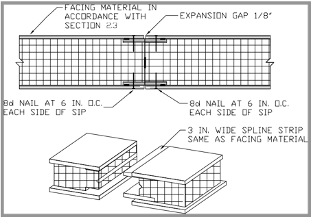
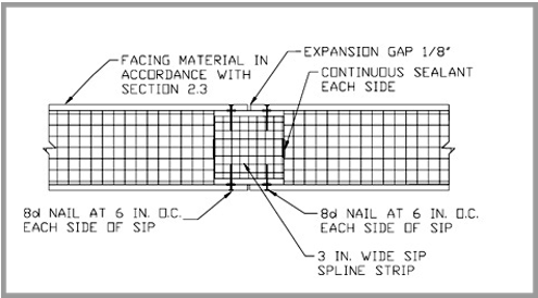
Spline: A long, narrow strip that fits into a groove cut into the longitudinal edges of the two structural insulated panels to be joined (refer to Figure 6.1). Alternately, the strip (spline) can be a section of structural insulated panel (insulated panel spline) with overall thickness equal to the core thickness of the two structural insulated panels to be connected (refer to Figure 6.2).
Story: That portion of the building included between the upper surface of any floor and the upper surface of the floor next above, except that the top-most story shall be that habitable portion of a building included between the upper surface of the top-most floor and the ceiling or roof above.
Story Above-Grade: Any story with its finished floor surface entirely above grade except that a basement shall be considered as a story above-grade when the finished surface of the floor above the basement is (a) more than 6 feet (1.8 m) above the grade plane, (b) more than 6 feet (1.8 m) above the finished ground level for more than 50 percent of the total building perimeter, or (c) more than 12 feet (3.7 m) above the finished ground level at any point.
Strap: Flat or coiled sheet steel material typically used for bracing and blocking which transfers loads by tension and/or shear.
Stud: Vertical structural element of a wall assembly, which supports vertical loads and/or transfers lateral loads.
Townhouse: A single-family dwelling unit constructed in a group of three or more attached units in which each unit extends from foundation to roof and with open space on at least two sides.
Truss: A coplanar system of structural members joined together at their ends usually to construct a series of triangles that form a stable beam-like framework.
Wall Height: The clear vertical distance between the finished floor and the finished ceiling. Where a finished floor does not exist (i.e., crawlspace), the wall height is the clear vertical distance between the interior finish grade and the finished ceiling.
Structural Walls: See Load Bearing Walls.
Non-Structural Walls: See Non-Load Bearing Walls.
Wind Exposure: Refer to Exposure Categories.
Wind Load: The force or pressure exerted on a building structure and its components resulting from wind. Wind loads are typically measured in pounds per square foot (psf) or Pascals (Pa).
Wind Speed: Refer to Design Wind Speed.
2.0 MATERIALS, SHAPES, AND STANDARD SIZES
2.1 Physical Dimensions
Walls for residential structures constructed with structural insulated panels (SIP) systems in accordance with this document shall comply with the shapes and minimum cross-sectional dimensions required in this section. SIP walls not in compliance with this section shall be constructed in accordance with accepted engineering practices, manufacturer’s recommendations, or an approved design.
2.1.1 SIP Wall Systems
SIPs for above grade wall construction shall comply with Figures 2.1 and 2.2 and shall have minimum panel thickness as specified in Section 2.2. Alternate SIP wall panel configurations that can demonstrate equivalency to SIP wall panels specified in this document shall be permitted. Each SIP wall panel shall be identified by grade mark and/or certificate of inspection issued by an approved agency as per Section 2.7.
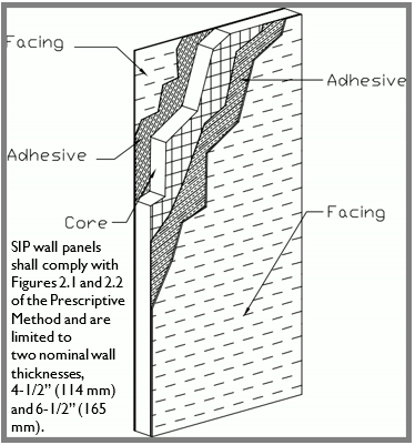
SIP Wall Components
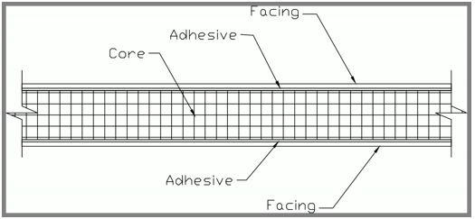
Cross Sectional View of SIP
2.2 Core Materials
The core material of SIPs used in wall construction shall be composed of molded expanded polystyrene (EPS) meeting the requirements of ASTM C 578 [5], type I, with minimum density of 0.90 lb/ft3 (14.42 kg/m2), or an approved alternate. Flame- spread rating of SIP cores shall be less than 75 and the smoke-development rating shall be less than 450, as tested in accordance with ASTM E 84 [4]. The minimum thickness of the core for SIP walls shall be 3.5 inches (89 mm). SIP core insulation shall bear a label containing the following as a minimum:
- Manufacturer identification,
- Product standard and type,
- Flame-spread/smoke-developed,
- Name, logo or identification of quality assurance
2.3 Facing Materials
Facing material for SIP walls shall be of wood structural panels used for structural purposes conforming to DOC PS 1 [12], DOC PS 2 [11] or, when manufactured in Canada, CSA O437 [14] or CSA O325 [13] and shall meet the following requirements:
- 7/16 inch (11 mm) thickness or greater,
- Panels identified by a trademark issued by an approved agency in accordance with DOC PS2 [11],
- Strength, stiffness, tension, and density meeting the requirements of Table 2.1 [6].
Table 2.1
Minimum Properties for OSB Skins Used in SIP Walls(a)
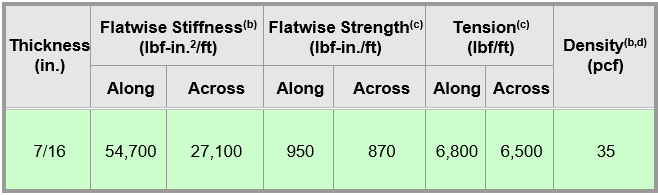
Table 2.1 Notes:
(a) Tested in accordance with ICC-ES Qualification of Alternate Sources of OSB for Facers of Sandwich Panels with Foam Plastic Cores dated August 3, 2005.
(b) Mean test value.
(c) Characteristic test value (5th percentile with 75% confidence).
(d) Based on oven-dry weight and oven-dry volume.
2.4 Adhesive Materials
Expanded polystyrene (EPS) core insulation shall be adhered to wood structural panel facers with adhesives specifically intended for the lamination of SIPS conforming to ASTM D2559 [7] or type II class 2 in accordance with ICC ES Acceptance Criteria AC 05 [17]. Each container of adhesive shall bear a label with the adhesive manufacturer identification (such as name or logo), adhesive name and type and the name (or logo) of the certifying quality assurance agency.
2.5 Lumber
Lumber framing material used for SIPs prescribed in the Prescriptive Method shall be No. 2 Spruce-pine-fir (SPF) or equivalent. The use of wood species/grades that meet or exceed the mechanical properties and specific gravity of No. 2 SPF shall be permitted.
2.6 Fasteners
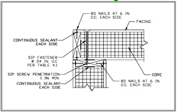
Fasteners (such as screws) used for the connection of SIP wall to wood members as specified in this document shall be corrosion resistant, have threaded or drill point and shall be sized to penetrate a minimum of 1 inch (25.4 mm) into the wood member to which the SIP assembly is being attached as shown in Figure 6.3. SIP Fasteners shall meet the following requirements:
- Nominal thread diameter 0.255 inch (7 mm),
- Nominal shank diameter 0.190 inch (5 mm)
- Nominal head diameter 0.625 inch (16 mm).
SIP fasteners shall have a minimum edge distance of 1-9/16 inch (40 mm) and a maximum edge distance of 2-7/8 inch (73 mm).
Galvanized screws, nails or staples shall be permitted for spline and plate attachments.
2.7 Labeling
All SIPs used in wall construction shall be identified by grade mark and/or certificate of inspection issued by an approved agency. The identification shall have the following minimum requirements:
- Manufacturer Identification (such as name or logo)
- Quality Assurance Agency Identification (such as name or logo)
- Conformance with this document
3.0 FOUNDATIONS
The building foundations shall comply with the applicable building code(s). Structural insulated wall panels shall be anchored to the foundation structure according to the requirements of Sections 4.0 and 6.0 of this course.
Ch. 4 Sip Above-Grade Walls
4.1 SIP Above-Grade Wall Requirements
SIPs used for above-grade walls shall be constructed in accordance with the provisions of this section and Figures 4.1 to 4.7. The minimum length of SIP wall without openings and lintel requirements above wall openings shall be in accordance with Section 5.0.
Lateral support for above-grade SIP walls shall be provided by the roof, floor, and interior braced framing systems in accordance with standard engineering practice. Connection details are provided in Section 6.0. The minimum SIP wall thickness shall be greater than or equal to the SIP wall thickness given in Tables 4.2 and 4.3.
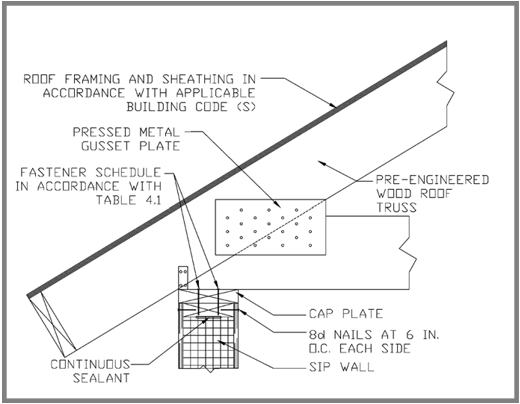
Wood framing and structural insulated wall panels shall be fastened through both facing surfaces to other wood building components in accordance with Table 4.1, unless otherwise provided for in this document.
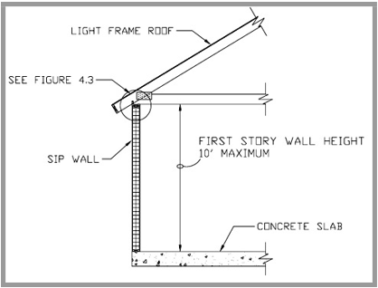
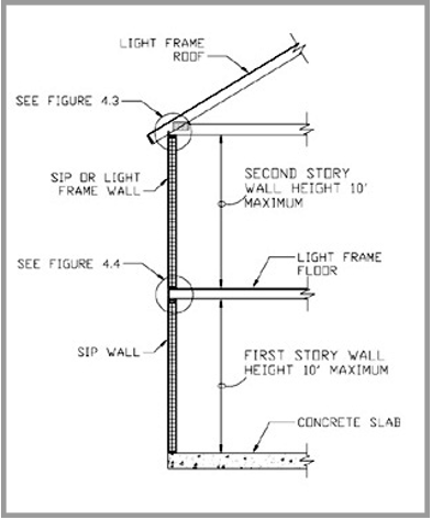
The nominal SIP wall thickness, for wall panels not taller than 10 feet (3048 mm), shall be determined in accordance with Tables 4.2 and 4.3. SIP walls taller than 10 feet (3048 mm) shall be constructed in accordance with an approved design.
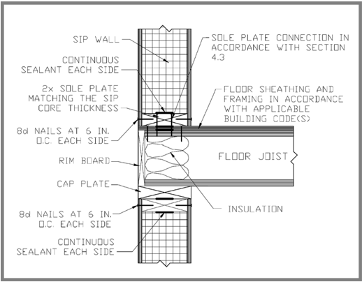
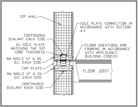
4.2 Top Plate
SIPs used in wall construction shall be capped with a top plate to provide overlapping at corners, intersections and splines in accordance with Figure 4.6. End joints in top plates shall be offset at least 24 inches (610 mm). Plates shall be a nominal 2 inches (51 mm) in depth and have a width equal to the width of the SIP (wall) core.
4.3 Bottom (sill) Plate
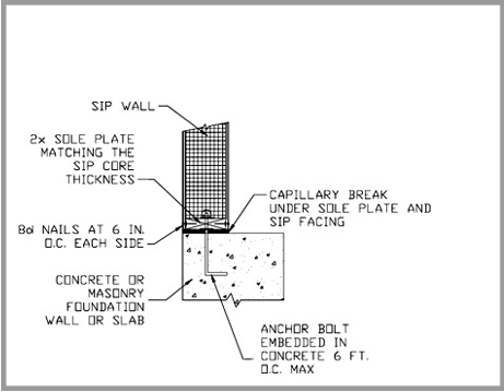
SIP walls shall have full bearing on pressure treated sill plates each having a width equal to the nominal width of the SIP core. When structural insulated wall panels are supported directly on continuous foundations in accordance with Figure 4.8, the wood sill plate at exterior walls on monolithic slabs and wood sill plates shall be anchored to the foundation with anchor bolts spaced a maximum of 6 feet (1,829 mm) on center. There shall be a minimum of two bolts per plate section with one bolt located not more than 12 inches (305 mm) or less than seven bolt diameters from each end of the plate section. Bolts shall be at least 1/2 inch (12.7 mm) in diameter and shall extend minimum of 7 inches (178 mm) into masonry or concrete. Foundation anchor straps, spaced as required can be used to provide equivalent anchorage to 1/2-inch-diameter (12.7 mm) anchor bolts.
Interior bearing wall sill plates on monolithic slab foundations shall be positively anchored with approved fasteners. A nut and washer shall be tightened on each bolt to the plate.
4.4 SIP Wall Bracing
Walls constructed with SIPs shall be considered fully sheathed walls (i.e., continuous wood structural panel sheathing). Tables 4.4 and 4.4a shall be used for determining the length requirements for braced wall panels (full height braced wall panels). Openings (such as for doors and windows) in SIP walls shall be permitted provided that the wall bracing requirements meet or exceed those specified in Tables 4.4 and 4.4a.
The bracing amounts in Table 4.4a shall be permitted to be multiplied by a factor of 0.9 for walls with a maximum opening height that does not exceed 85 percent of the wall height or a factor of 0.8 for walls with a maximum opening height that does not exceed 67 percent of the wall height. Braced wall panels (i.e., full height SIP) shall begin no more than 12.5 feet (3,810 mm) from each end of a braced wall line. Braced wall panels (i.e., full height SIPs) that are counted as part of a braced wall line shall be in line, except that offsets out-of-plane of up to 4 feet (1,219 mm) shall be permitted provided that the total out-to-out offset dimension in any braced wall line is not more than 8 feet (2,438 mm).
4.4.1 Spacing of SIP Wall Bracing
Spacing of braced SIP wall lines shall not exceed 35 feet (10,668 mm) on center along both the length and the width of each story of a building.
Exception: Spacing of braced SIP wall lines not exceeding 50 feet shall be permitted where:
- The wall bracing provided equals or exceeds the amount of bracing required by Table 4 multiplied by a factor equal to the braced wall line spacing divided by 35 feet (10,668 mm), and
- The length-to-width ratio for the floor/wall diaphragm does not exceed 3:1.
4.5 Above-Grade SIP Wall Coverings
4.5.1 Interior Covering
The interior facing of SIP walls located along interior habitable spaces shall be covered with a minimum of ½-inch (13-mm) gypsum board or an approved finish material that provides a thermal barrier to limit the average temperature rise of the unexposed surface to no more than 250 degrees F (139 °C) after 15 minutes of fire exposure as tested in accordance with ASTM E119 [8]. The use of vapor retarders and air barriers shall be in accordance with the authority having jurisdiction.
4.5.2 Exterior Covering
SIP walls shall be protected from physical damage. All SIP walls in exterior applications shall be covered with approved materials installed to provide a barrier against the weather (such as sunlight, snow, and rain). The exterior wall envelope shall be designed with a water-resistive barrier behind the exterior veneer. The water-resistive barrier shall be one layer of No. 15 felt, free from holes and breaks, complying with ASTM D226 [15] for Type I felt or other approved equal.
4.6 SIP Wall Penetrations
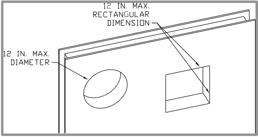
The internal vertical chase penetration in the SIP core shall have a maximum side dimension of 2-inches (51 mm) centered in the panel core. Vertical chases shall have a minimum spacing of 24-inches (610 mm) on center. A maximum of 2 horizontal chases shall be permitted in each wall panel-one at 14-inches (360 mm) and one at 4-feet (1,219 mm) from the bottom of the panel.
The maximum allowable penetration size in a SIP wall panel shall be limited to a 12-inch (305 mm) circular or 12-inch by 12-inch (305 mm x 305 mm) rectangular section in accordance with Figure 4.7. Over-cutting of holes in facing panels shall not be permitted without an approved design.
3.7 Interior Load-Bearing Walls
Interior load-bearing walls shall be constructed as specified in the building code or by the authority having jurisdiction.
Table 4.1
Fastener Schedule for SIP Construction
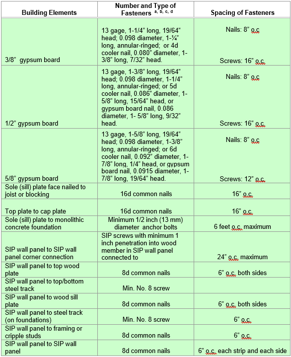
Table 4.1 Notes:
For SI: 1 inch = 25.4mm, 1 foot = 304.8 mm, 1 mph = 1.61 km/h, 1 ksi = 6.895 MPa
a. All nails are smooth-common, box or deformed shanks except where otherwise Nails used for framing and sheathing connections shall have minimum average bending yield strengths as shown: 80 ksi for shank diameter of 0.192 inch (20d common nail), 90 ksi for shank diameters larger than 0.142 inch but not larger than 0.177 inch, and 100 ksi for shank diameters of 0.142 inch or less.
b. Staples are 16-gage wire and have a minimum 7/16-inch crown
c. Nails shall be spaced at not more than 6 inches on center at all supports where spans are 48 inches or
d. Screws shall be Type S or W per ASTM C 1002 [16] and shall be sufficiently long to penetrate wood framing not less than 5/8 inch and metal framing not less than 3/8 inch.
Table 4.2
Nominal Thickness (Inches) for SIP Walls Supporting SIP or Light-Frame Roofs Only1
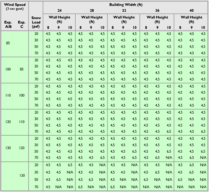
Table 4.2 Notes:
For SI: 1 inch = 25.4 mm, 1 foot = 304.8 mm, 1 mph = 1.61 km/hr.
1 Deflection criteria: L/240.
1 Roof dead load: 10 psf maximum. Roof live load: 70 psf maximum Ceiling dead load: 5 psf maximum. Ceiling live load: 20 psf maximum.
1 N/A indicates not applicable (design required).
Table 4.3
Nominal Thickness (Inches) of SIP Walls Supporting SIP or Light-Frame Story and Roof1
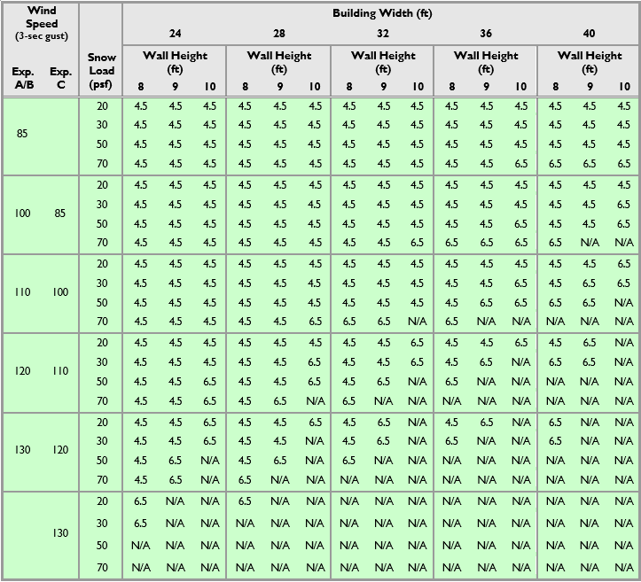
Table 4.3 Notes:
For SI: 1 inch = 25.4 mm, 1 foot = 304.8 mm, 1 mph = 1.61 km/hr
1 Deflection criteria: L/240
1 Roof dead load: 10 psf maximum Roof live load: 70 psf maximum Ceiling load: 5 psf maximum Ceiling live load: 20 psf maximum
1 Second floor live load: 30 psf maximum Second floor dead load: 10 psf
1 Second floor wall dead load: 10 psf
1 N/A indicates not applicable (design required)
Table 4.4
SIP Wall Bracing Requirements
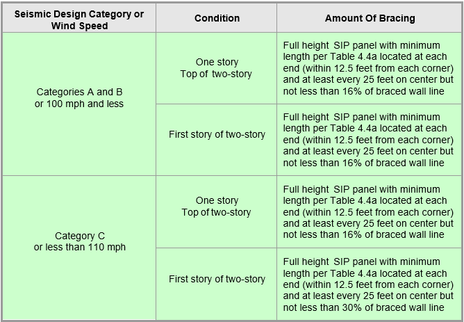
Table 4.4 Notes:
For SI: 1 inch = 25.4 mm, 1 foot = 304. 1 mph = 1.61 km/h.
Table 4.4a
Requirements for Braced SIP walls1,2
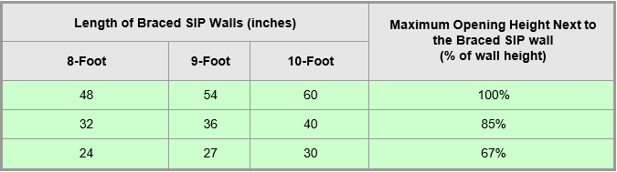
Table 4.4a Notes:
For SI: 1 inch = 25.4 mm, 1 foot = 305 mm.
1 Linear interpolation shall be
2 Full-height SIP to either side of garage openings that support light frame roofs with roof covering dead loads of 3 psf or less shall be permitted to have a 4:1 aspect ratio.
Notes:
- Top plates shall be continuous over
- SIP facing surfaces shall be nailed to framing and cripples with 8d common or box nails spaced 6 inches (152 mm) on center, staggering alternate nails ½ inch (13 mm).
- Galvanized nails shall be hot-dipped or tumbled. Framing shall be attached in accordance with building code requirements unless otherwise provide for in this document.
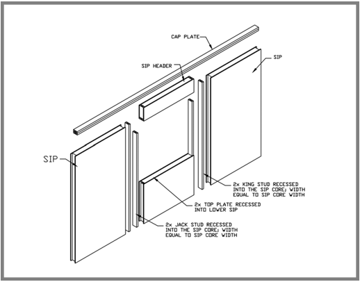
Ch. 5 Sip Header Requirements
Structural insulated panel (SIP) wall headers shall be designed and constructed according to Table 5.1 and Figure 4.6. SIP headers shall be continuous sections without splines. Headers longer than 4 ft (1,219 mm) shall be constructed according to Section 5.1. The top plate shall be continuous over the header.
Table 5.1
Maximum Span (Feet) For SIP Headers
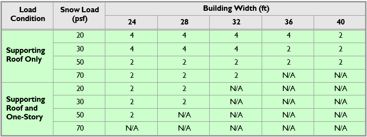
Table 5.1 Notes:
For SI: 1 inch = 25.4 mm, 1 foot = 304.8 mm Deflection criteria: L/240
Roof dead load: 10 psf maximum Ceiling dead load: 5 psf maximum Second floor live load: 30 psf maximum
Second floor dead load: 10 psf maximum
Second floor dead load from walls: 10 psf maximum N/A indicates not applicable (design required)
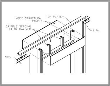
5.1 Wood structural panel box headers
Wood structural panel box headers are permitted to be used where SIP headers are not applicable. Wood structural panel box headers shall be constructed in accordance with Figure 5.1 and Table 5.2. The top plate shall be continuous over the header. Jack studs shall be used for spans over 4 feet (1,219 mm). Wood structural panel faces shall be single pieces of 15/32-inch-thick (12 mm) or thicker Exposure 1, installed on the interior or exterior or both sides of the header. Wood structural panel faces shall be nailed to framing and cripples with 8d common or galvanized box nails spaced 3 inches (76 mm) on center, staggering alternate nails ½ inch (12.7 mm).
Table 5.2
Maximum Span (Feet) for Wood Structural Panel Box Headers a
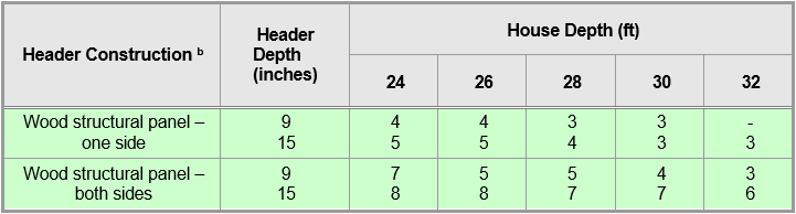
Table 5.2 Notes:
For SI: 1 inch = 25.4 mm, 1 foot = 304.8 mm.
a. Spans are based on single story with clear-span trussed roof, top story of two-story with a clear-span trussed roof, or two-story with floor and roof supported by interior-bearing walls.
b. See Figure 5.1 for construction details.
6.0 SIP CONNECTION DETAILS
6.1 Wall Panel to Wall Panel Connection
Structural insulated panel walls shall be connected in accordance with Figures 6.1, Figure 6.2, or by other approved method.
6.2 Corner Framing
Corner framing of structural insulated panel walls shall be constructed in accordance with Figure 6.3 or other approved method.
7.0 UTILITIES
7.1 Plumbing Systems
Plumbing shall comply with the provisions of the IRC or the applicable plumbing code. Plumbing is not normally run through foam core panels. The panels are typically used for exterior walls, and as in consistent with good building practice, plumbing should be kept out of exterior walls to avoid freezing.
7.2 HVAC Systems
HVAC installation shall comply with the provisions of the IRC or the applicable mechanical and/or energy code. SIP homes require no special heating system. Forced air, electric, solar, radiant and wood burning systems are all suitable, though some are more appropriate than others for a specific home design. Central air conditioning requires ductwork and is therefore most compatible with forced-air heating systems. Because of the home’s tight construction, the fireplaces, wood burners, furnaces and any other combustion appliances should be supplied with an outside source of combustion air.
7.3 Electrical Systems
Electrical system installation shall comply with the National Electric Code [9].
8.0 THERMAL GUIDELINES
8.1 Energy Code Compliance
The insulation value (R-value) of SIP wall systems shall meet or exceed the applicable provisions of the IRC, local energy code, or the ICC Energy Conservation Code [10].
8.2 Moisture
SIP wall panels shall be protected from moisture intrusion through the use of approved exterior wall finishes in accordance with Section 4.0. SIP walls that become excessively wet or damaged shall be removed and replaced before proceeding with the installation of additional panels or other work.
8.3 Ventilation
The natural ventilation rate of SIP buildings shall not be less than that required by the local code or 0.35 ACH when no local code exists. When required, mechanical ventilation shall be provided to meet the minimum air exchange rate of 0.35 ACH. A properly constructed SIP home has a very low air infiltration rate. That’s great for reducing heating and cooling costs, but it isn’t always healthy for the home or its occupants. It is strongly recommended that a whole-house ventilating system be installed at the time of construction.