Ch. 1 Basics of Residential Construction
1.1 Conventional Residential Construction
The conventional American house has been shaped over time by a variety of factors. Foremost, the abundance of wood as a readily available resource has dictated traditional American housing construction, beginning as log cabins, then as post-and-beam structures, and finally as light-frame buildings. The basic residential construction technique, which has remained much the same since the introduction of light wood-framed construction in the mid-1800s, is generally referred to as conventional construction. See figures 1.1a through 1.1c for illustrations of various historical and modern construction methods using wood. Today, a wood framed residential building can be typically constructed in one of two ways: (1) conventionally framed, constructed from wall panels built in a factory, and assembled on the jobsite, or (2) built in a factory and brought to a jobsite and placed on a site-built foundation.
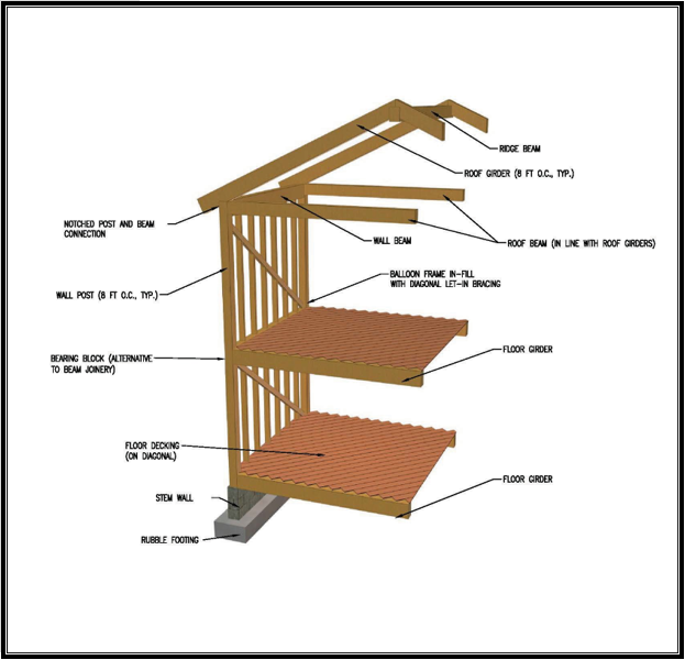
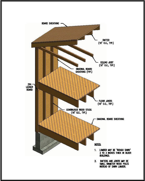
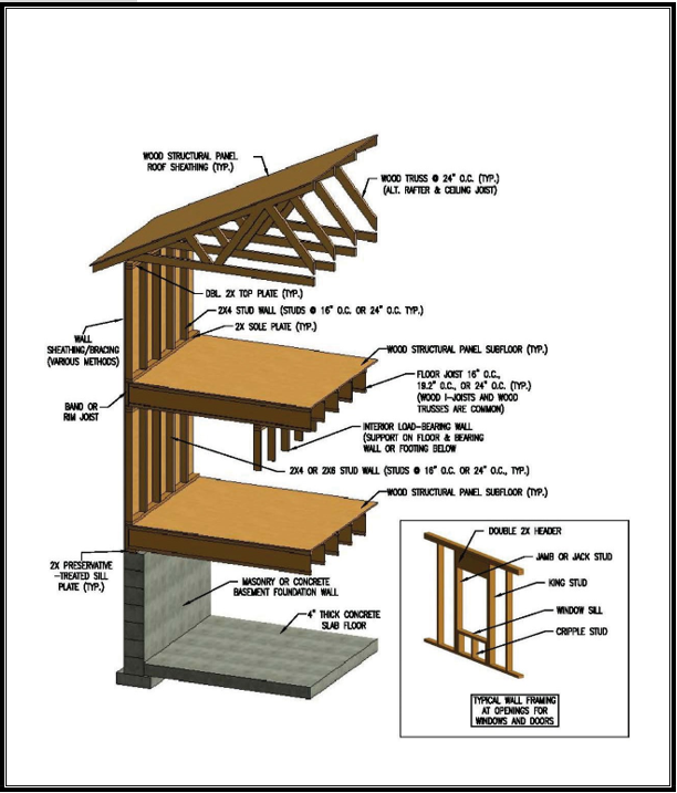
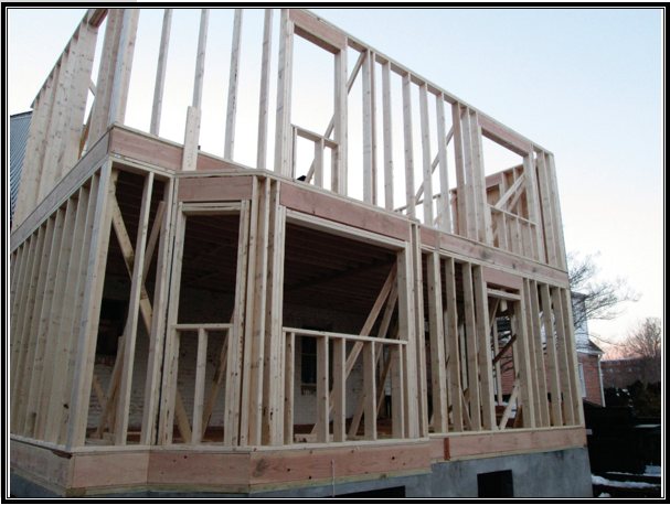
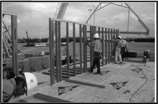
In post-and-beam framing, structural columns support horizontal members. Post-and-beam framing is typified by the use of large timber members. Traditional balloon framing consists of closely spaced light vertical structural members that extend from the foundation sill to the roof plates. Platform framing is the modern adaptation of balloon framing, whereby vertical members extend from the floor to the ceiling of each story. Balloon and platform framings are not simple adaptations of post-and-beam framing but are actually unique forms of wood construction. Platform framing is used today in most wood-framed buildings; however, variations of balloon framing may be used in certain parts of otherwise platform-framed buildings, such as great rooms, stairwells, and gable- end walls, where continuous wall framing provides greater structural integrity. Figure 1.2 depicts a modern home under construction.
Conventional or prescriptive construction practices are based as much on experience as on technical analysis and theory (HEW, 1931). The minimum building code requirements provided by the International Residential Code (IRC) have codified conventional construction practices but do have some basis in basic engineering principles. The prescriptive construction requirements provided in the IRC are intended to be easy for a builder to follow and for a code official to inspect without the services of a design professional. It is also common for design professionals, including architects and engineers, to apply conventional practices in typical design conditions but to undertake special designs for certain parts of a home that are beyond the scope of the IRC or a prescriptive residential design guide. It is very important for design professionals to understand the limitations of the prescriptive code when relying on it.. The housing market historically has operated with minimal involvement of design professionals. As building codes advance, environmental loads become better understood, and performance demands on residential construction continue to increase, however, so too does the role of the design professional. Section 1.5 explores the current role of design professionals in residential construction.
Although dimensional lumber has remained the predominant material used in the last century of American housing construction, the size of the material has been reduced from the rough-sawn, 2-inch-thick members used in the late 1800s to today’s nominal dressed sizes, with actual thicknesses of less than 1.5 inches for standard framing lumber. The result has been a significant improvement in economy and resource use accompanied by significant structural tradeoffs.
The mid-to-late 1900s also saw several significant innovations in pre- engineered wood products and wood-framed construction techniques. One example is the development of the metal plate-connected wood truss in the 1950s. Metal plate-connected wood trusses, most often referred to as pre-engineered wood trusses, are now used in many new homes because the pre-engineered method is generally more efficient than older framing methods that rely on roof rafters. In addition to being used in roof framing, pre-engineered wood trusses and beams are also used in floor framing. As floor framing, these trusses are able to increase floor rigidity and the spans of flooring systems, eliminating some interior load-bearing walls. Other examples of innovative products and techniques are plywood structural sheathing panels that entered the market in the 1950s and oriented strand board (OSB) that entered the market in the 1980s. Both products quickly replaced board sheathing on walls, floors, and roofs.
It is important to recognize that, while the previously mentioned changes in materials and methods were occurring, significant changes in house designs also occurred, in the way of larger homes with more complicated architectural features, long-span floors and roofs, and large open interior spaces. The collective effect of these changes on the structural qualities of most homes is certainly notable.
The following references are recommended for a more in depth understanding of conventional housing design, detailing, and construction. Section 1.8—References—provides detailed citations.
- 2012 International Residential Code (ICC, 2012a).
- 2012 International Building Code (ICC, 2012b).
- Wood Frame Construction Manual (AWC, 2012b).
- Modern Carpentry—Building Construction Details in Easy-to-Understand Form, 10th ed. (Wagner, 2003).
The following structural design references are also recommended for use with chapters 3 through 7 of this guide.
- NDS—National Design Specification for Wood Construction and Supplement (AWC, 2012a).
- ACI-318—Building Code Requirements for Structural Concrete (ACI, 2011a).
- ACI-530—Building Code Requirements for Masonry Structures (ACI, 2011).
- ASCE 7-10—Minimum Design Loads for Buildings and Other Structures (ASCE, 2010).
1.2 Factory-Built Housing
Most homes in the United States are still site built; that is, they follow a stick-framing approach. With this method, wood members are assembled on site from the foundation up. The primary advantage of onsite building is flexibility in meeting variations in housing styles, design details, and changes specified by the owner or builder. An increasing number of today’s site-built homes, however, use components that are fabricated in an offsite plant. Prime examples include wall panels (both structural insulated panels [SIPs] and those built with dimensional lumber) and pre-engineered wood trusses. The blend of stick-framing and factory- built components is referred to as component building.
Modular housing is a step beyond component building. Modular housing is constructed in essentially the same manner as site-built housing except that houses are factory-built in finished modules (typically two or more modules) and shipped to the jobsite for placement on site-built foundations. Modular housing is built to comply with the same building codes that govern site-built housing.
Manufactured housing (formerly known as mobile homes) is also constructed using wood-framed methods and components; however, these methods and components are required to comply only with the federal preemptive standards specified in the Manufactured Housing Construction Safety Standards (U.S. Department of Housing and Urban Development code). This popular form of industrialized housing is completely factory assembled and then delivered to a site by using an integral chassis for over-the-road travel and foundation support.
1.3 Alternative Materials and Methods
Several innovations in structural materials have been introduced more recently to residential construction. Alternatives to conventional wood-framed construction are in fact gaining recognition in modern building codes. It is important for designers to become familiar with these alternatives because their effective integration into conventional home building may require the services of a design professional. In addition, a standard practice in one region of the country may be viewed as an alternative in another, which provides opportunities for innovation across regional norms.
Many options in the realm of materials are already available. The following pages describe several significant examples. In addition, the following contacts are useful for obtaining design and construction information on the alternative materials and methods for house construction.
General contacts
HUD User (http://huduser.gov).
ToolBase (http://toolbase.org).
Engineered wood products
American Wood Council (http://awc.org).
APA–The Engineered Wood Association (http://apawood.org).
Structural Building Components Association (http://sbcindustry.com).
Cold-formed steel
Steel Framing Alliance (http://steelframingalliance.com).
American Iron and Steel Institute (http://steel.org).
Cold-Formed Steel Engineers Institute (http://cfsei.org).
Insulating concrete forms
EPS Industry Alliance (http://forms.org).
Structural Insulated Panels
Structural Insulated Panel Association (http://www.sips.org).
Masonry
National Concrete Masonry Association (http://ncma.org).
Engineered wood products and components (see figure 1.3) have gained considerable popularity in the past 30 years. Engineered wood products and components include wood-based materials and assemblies of wood products with structural properties similar to or better than the sum of their component parts. Examples include metal plate-connected wood trusses, wood I-joists, laminated veneer lumber (LVL), plywood, oriented strand board (OSB), glue- laminated lumber, and parallel strand lumber (PSL). OSB structural panels are rapidly displacing plywood as a favored product for wall, floor, and roof sheathing. Wood I-joists are now used in 54 percent of the total framed floor area in all new homes each year (APA, 2013). Cross-laminated timber, (CLT) is now being manufactured in Canada, consists of laminated layers of solid sawn or structural composite lumber that are bonded with structural adhesives to form a rectangular-shaped timber. This product is expected to be more widely available in the United States in coming years.
The increased use of engineered wood products is the result of many years of research and product development and, more importantly, reflects the economics of the building materials market. Engineered wood products often offer improved dimensional stability, increased structural capability, ease of construction, and more efficient use of the nation’s lumber resources, and they do not require a significant change in construction technique.
The designer should, however, carefully consider the unique detailing and connection requirements associated with engineered wood products and ensure that the requirements are clearly understood in the design office and at the jobsite. Design guidance, such as span tables and construction details, is usually available from the manufacturers of these predominantly proprietary products. A note of caution: for these proprietary products to be supported by the manufacturer, they must be installed exactly in accordance with the manufacturer’s instructions.
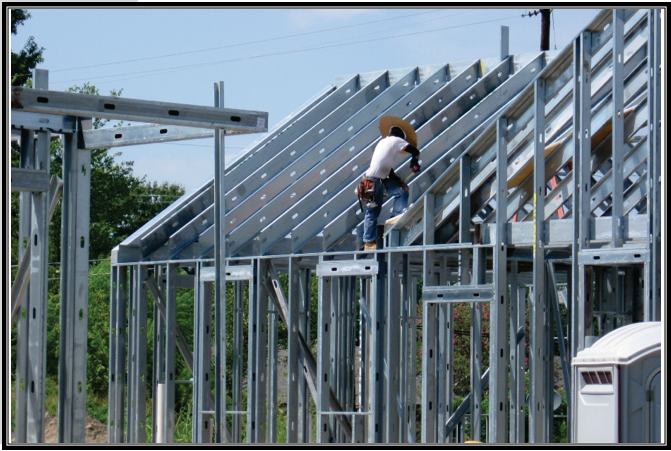
Cold-formed steel framing (previously known as light-gauge steel framing) was originally produced by a fragmented industry with nonstandardized products serving primarily the commercial design and construction market. In cooperation with the industry, HUD sponsored research necessary to develop standard minimum dimensions and structural properties for basic cold-formed steel framing materials, which resulted in the development of IRC design provisions. Cold-formed steel framing is currently used in exterior and interior walls of new housing starts. The benefits of cold-formed steel include low cost, durability, light weight, and strength (HUD, 1994). Figure 1.4 illustrates the use of cold-formed steel framing in a home. Construction methods can be found in the International Residential Code (ICC, 2012a).
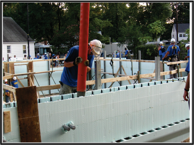
Insulating concrete form (ICF) construction, as illustrated in figure 1.5, combines the forming and insulating functions of concrete construction in a single step. In a cooperative effort between the housing industry and HUD, the product class was included in the I-Codes after the establishment of minimum dimensions and standards for ICF construction. The benefits of ICF construction include durability, strength, noise control, and energy efficiency (HUD, 1998a; HUD, 1998b). The method, detailed in Prescriptive Method for Insulating Concrete Forms in Residential Construction, has been adopted by the IRC and is also discussed in the Prescriptive Design of Exterior Concrete Walls (PCA, 2012).
Structural insulated panels (SIPs), are composite panels of polystyrene or polyurethane foam sandwiched on both sides with OSB sheets. The panel size is typically the same as the manufactured size of the OSB sheets, but SIPs can also be larger. Individual SIPs are connected together by a vertical spline (splice) consisting of a 3-inch-wide OSB strip that bridges an expansion gap between the SIPs and is nailed to the OSB sheets on each side. A sufficient amount of foam is removed to allow the top and bottom plates to fit snugly inside the OSB. For additional stiffness, a further section of foam can be removed to accommodate abutting 2x studs or a foam block at the spline. This construction method eliminates the need for other insulation on the walls and roofs.
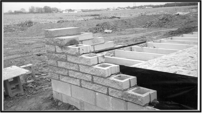
Concrete masonry construction, illustrated in figure 1.6, has remained essentially unchanged in its basic construction method. Recently introduced products offer innovations that provide structural and architectural benefits, however. Masonry construction is well recognized for its fire-safety qualities, durability, noise control, termite resistance, and strength. The installed cost of masonry construction, like most alternatives to conventional wood-framed construction, may be a local issue that needs to be balanced against other factors. For example, in hurricane-prone regions along the Gulf Coast and southern Atlantic states, standard concrete masonry construction dominates the market because its performance in major hurricanes has been favorable when nominally reinforced using conventional practices.
Reinforced concrete construction is a frequently used material and method in nonresidential construction that is gaining popularity in home construction in some parts of the country. This gain is because of its performance in extremely hot climates, in those locations with termite or woodboring insect issues, in those locations subject to either hurricane- or tornado-force winds, and for those building owners who want an exterior less prone to deterioration and severe weathering. Construction techniques in forming and pouring concrete for homes are the same as used for nonresidential construction.
Alternative materials and methods provisions exist within the IRC and the International Building Code (IBC). These building code provisions provide the flexibility for a design professional or builder to use new materials in construction that may not be discussed or even contemplated in building codes. The IRC and IBC provide this flexibility within chapter 1, which describes a process whereby the designer or builder and the code official can review and approve such approaches.
1.4 Building Codes and Standards
Most of the U.S. population lives in areas that are covered by legally enforceable building codes that govern the design and construction of buildings, including residential dwellings. Although building codes are legally a governmental police power, most states allow local political jurisdictions to adopt or modify building codes to suit their special needs or, in a few cases, to write their own code. Almost all jurisdictions adopt a family of model codes by legislative action instead of attempting to write their own code.
The dominant family of model building codes in the United States is that developed by the International Code Council (ICC). The ICC was founded in 1994 by the three regional code organizations—Building Officials and Code Administrators International, Inc.; International Conference of Building Officials; and Southern Building Code Congress International, Inc. This initiative was the result of the conclusion by the founders that the nation needed a single set of model building codes. The ICC has developed codes for all types of buildings and occupancies—from a backyard storage shed to a highrise office building and sports complex. In addition, some jurisdictions have also adopted building codes developed by the National Fire Protection Association (NFPA). The two major building code organizations are—
- International Code Council
500 New Jersey Avenue, NW
Washington, DC 20001
http://iccsafe.org - National Fire Protection Association
1 Batterymarch Park
Quincy, MA 02169
http://nfpa.org
In the past, although the dominant codes included some “deemed-to- comply” prescriptive requirements for conventional house construction, they focused primarily on performance (that is, engineering) requirements. By focusing more on performance requirements, these codes were better able to address more complex buildings across the whole range of occupancy and construction types. Therefore, in an effort to provide a comprehensive, easier to use code for residential construction, the IRC was developed. Presented in logical construction sequence, the IRC is devoted entirely to simple prescriptive requirements for one- and two-family dwellings, duplexes, and townhouses. Many state and local jurisdictions have adopted both the IRC and the IBC. Thus, designers and builders enjoy a choice as to which set of requirements best suits their purpose.
Model building codes do not provide detailed specifications for all building materials and products but rather refer to established industry standards,
such as those promulgated by ASTM International, formerly known as the American Society for Testing and Materials (ASTM). Several ASTM standards are devoted to the measurement, classification, and grading of wood properties for structural applications and of virtually all other building materials, including steel, concrete, and masonry. Design standards and guidelines for wood, steel, concrete, and other materials or applications are also maintained as reference standards in building codes. More than 600 materials and testing standards from a variety of organizations currently are referenced in the building codes used in the United States.
For products and processes not explicitly recognized in the codes or standards, the ICC Evaluation Service, Inc. (ICC-ES) provides evaluations of products relative to the model code requirements. The ICC-ES report recognizes a specific building product’s ability to meet the performance and prescriptive provisions in the code. It is an independent finding of the product’s capability. The report provides engineers the assurance of validity and technical accuracy in determining a product’s correct application. Reports are valid for a specific period of time. A report can undergo revisions at any time. Other organizations—such as Intertek, the International Association of Plumbing and Mechanical Officials, and Miami-Dade County, Florida—provide testing of building products for performance certifications and building code compliance.
Seasoned designers spend countless hours in careful study and application of building codes and selected standards that relate to their area of practice. These designers develop a sound understanding of the technical rationale and intent behind various provisions in applicable building codes and design standards. This experience and knowledge, however, can become even richer when coupled with practical experiences from the field. One of the most valuable sources of practical experience is the study of the successes and failures of past designs and construction practices, as presented in section 1.6.
1.5 Role of the Design Professional
Because the primary user of this guide is assumed to be a design professional, it is important to understand the role that design professionals can play in the residential construction process, particularly regarding recent trends. Design professionals offer a wide range of services to builders or developers in the areas of land development, environmental impact assessments, geotechnical and foundation engineering, architectural design, structural engineering, and construction monitoring. This guide, however, focuses on two approaches to design, as follows.
- Conventional design. Sometimes referred to as “prescriptive” construction, conventional design relies on standard practice and empirical methods as governed by prescriptive building code requirements (see section 1.4). This prescriptive approach, however, does not preclude and may even require some parts of the structure to be specially designed by an engineer or architect.
- Engineered design. Engineered design generally involves the application of engineering practice as represented within the building codes and design standards.
Some of the conditions that typically cause concern in the planning and preconstruction phases of home building and thus sometimes create the need for professional design services are—
- Structural configurations, such as unusually long floor spans, unsupported wall heights, large openings, or long-span cathedral
- Loading conditions, such as high winds, high seismic risk, flood risks, coastal construction, heavy snows, or abnormal equipment loads.
- Engineering certifications, such as those required in V-zone flood areas and California seismic areas.
- Nonconventional building systems or materials, such as composite materials, structural steel, or unusual connections and fasteners.
- Geotechnical or site conditions, such as expansive soil, variable soil or rock foundation bearing, flood-prone areas, high water tables, or steeply sloped sites.
- Owner’s requirements, such as special materials, appliance or fixture loads, atriums, and other special features.
Although some larger production builders produce sufficient volume to justify employing a full-time design professional, most builders use consultants on an as-needed basis. As more and more homes are built in earthquake-prone areas and along the hurricane-prone coastlines, however, the involvement of structural design professionals is increasing. The added complexities of larger custom-built homes and special site conditions further serve to spur demand for design professionals. Moreover, if nonconventional materials and methods of construction are to be used effectively, the services of a design professional are often required. In some instances, builders in high-hazard areas are using design professionals for onsite compliance inspection in addition to building design.
Although some larger production builders produce sufficient volume to justify employing a full-time design professional, most builders use consultants on an as-needed basis. As more and more homes are built in earthquake-prone areas and along the hurricane-prone coastlines, however, the involvement of structural design professionals is increasing. The added complexities of larger custom-built homes and special site conditions further serve to spur demand for design professionals. Moreover, if nonconventional materials and methods of construction are to be used effectively, the services of a design professional are often required. In some instances, builders in high-hazard areas are using design professionals for onsite compliance inspection in addition to building design.
1.6 Housing Structural Performance
1.6.1 General
Of the more than 130 million housing units in the United States, approximately two-thirds are single-family dwellings. With that many units in service, a substantial number can be expected to experience performance problems, most of which amount to minor defects that are easily detected and repaired. Other performance problems, such as foundation problems related to subsurface soil conditions, are unforeseen or undetected and may not be realized for several years.
On a national scale, tens of thousands of homes are subjected to extreme climatic or geologic events in any given year. Of that number, some will be damaged because of events that exceed the performance expectations of the building code (that is, a direct tornado strike or a large-magnitude hurricane, thunderstorm, flood, or earthquake). In addition, some will experience problems resulting from defective workmanship, premature product failure, design flaws, or durability problems (that is, rot, termites, or corrosion). Often, a combination of factors leads to the most dramatic forms of damage. Because the cause and effect of these problems do not usually fit simple generalizations, it is important to consider cause and effect objectively in terms of the overall housing inventory.
The role of building codes historically has been to ensure that an acceptable level of safety is maintained during the life of a house to limit life- threatening performance problems. Because the public may not benefit from an excessive degree of safety, code requirements must also maintain a reasonable balance between affordability and safety. As implied by any rational interpretation of a building code or design objective, safety must include an accepted level of risk. In this sense, economy, energy efficiency, sustainability, and affordability may be broadly considered as competing performance requirements. For a designer, the challenge is to consider optimum value and to use cost-effective design methods that result in acceptable building performance in keeping with the intent of the building code. In many cases, designers may be able to offer cost-effective options to builders and owners that improve performance well beyond the expected norm. Owners, however, must understand that they carry the burden of risk beyond what is implied in the building built “to code”.
Building codes today are focusing more on life-cycle performance— including durability, sustainability, energy usage, and efficiency—in addition to life safety. These building code requirements include improved performance in response to normal and common occurrences such as water leaks, sagging floors, surface resistance to weathering, and temperature extremes. Building code requirements also include improved performance in response to less frequent occurrences such as floods, hurricanes, and earthquakes. The designer needs to be familiar with techniques to improve performance in all these situations to better serve the client.
1.6.2 Common Building Performance Issues
Common building performance issues have been found to include water intrusion of building envelopes; water intrusion to basements and foundations; building movements because of soil conditions; and failures of roof coverings, exterior claddings, and interior finishes.
These issues do not result solely from building products, because builders are often averse to products that are “too new.” Products and systems that have been the subject of class-action lawsuits in the United States give builders some reason to think twice about specifying new products. Examples of such products and systems include—
- Exterior Insulation and Finish Systems (EIFS).
- Fire-retardant-treated, or FRT, plywood roof
- Certain composite sidings and exterior
- Polybutylene water
Recent issues with heavily used products that had been long accepted (formaldehyde in wood products and contaminated drywall) have served to reinforce builders’ concerns about product performance.
Note that many of these problems have been resolved by subsequent product improvements. It is unfortunately beyond the scope of this guide to give a complete account of the full range of problems experienced in housing construction.
1.6.3 Housing Performance in Hurricanes, Earthquakes, Floods, and Tornadoes
Scientifically designed studies of housing performance during natural disasters have permitted objective assessments of actual performance relative to that intended by building codes. Anecdotal damage studies, conversely, are often subject to notable bias. Both objective and subjective damage studies provide useful feedback to builders, designers, code officials, and others with an interest in housing performance. The issue of housing performance in high-hazard areas will continue to increase in importance, because nearly 50 percent of the U.S. population lives along coastlines, raising concerns about housing safety, affordability, and durability. Therefore, it is essential that housing performance be understood objectively as a prerequisite to guiding rational design and construction decisions. Proper design that takes into account the wind and earthquake loads discussed in chapter 3 and the structural analysis procedures addressed in chapters 4, 5, 6, and 7 will likely result in efficient designs that address the performance issues discussed in those chapters. Regardless of the efforts made in design, however, the intended performance can be realized only with an adequate emphasis on installed quality. For this reason, some builders in high-hazard areas have retained the services of design professionals as much for onsite compliance inspections as for their design services. This practice offers additional quality assurance to the builder, designer, and owner in high-hazard areas of the country. It is within these extreme events that most performance problems are observed, manifested, or exacerbated.
1.7 Summary
Housing in the United States has evolved over time under the influence of a variety of factors. Although available resources and the economy continue to play significant roles, building codes, consumer preferences, and alternative construction materials are becoming increasingly important factors. In particular, building codes in the United States require homes in many special high-hazard areas to be designed by design professionals rather than by following prescriptive construction practices. This apparent trend may be attributed in part to changing perceptions regarding housing performance in these high-risk areas. Therefore, greater emphasis must be placed on the efficient structural design of housing. Although efficient design should also strive to improve construction quality through simplified construction, it also places greater importance on the quality of installation required to achieve the intended performance without otherwise relying on overdesign to compensate partially for real or perceived problems in installation quality.
Ch. 2 Structural Design Concepts
2.1 General
This chapter reviews some fundamental concepts of structural design and presents them in a manner relevant to the design of light-frame residential structures. Those concepts form the basis for understanding the design procedures and the overall design approach addressed in the remaining chapters of the guide. With this conceptual background, it is hoped that the designer will gain a greater appreciation for creative and efficient design of homes, particularly the many assumptions that must be made.
2.2 What Is Structural Design?
The process of structural design is simple in concept but complex in detail. It involves the analysis of a proposed structure to show that its resistance or strength will meet or exceed a reasonable expectation. That expectation usually is expressed by a specified load or demand and an acceptable margin of safety that constitutes a performance goal for a structure.
The performance goals of structural design are multifaceted. Foremost, a structure must perform its intended function safely over its useful life. Safety is discussed later in this chapter. The concept of useful life implies considerations of durability and establishes the basis for considering the cumulative exposure to time- varying risks (that is, corrosive environments, occupant loads, snow loads, wind loads, and seismic loads). Given that performance and cost are inextricably linked,
however, owners, builders, and designers must consider economic limits to the primary goals of safety and durability.
Maintaining the appropriate balance between the two competing considerations of performance and cost is a discipline that guides the “art” of determining value in building design and construction. Value is judged by the “eye of the beholder,” however, and what is an acceptable value to one person may not be acceptable to another (for example, too costly versus not safe enough or not important versus important). For this reason, political processes factor into the development of minimum goals for building design and structural performance, with minimum value decisions embodied in building codes and engineering standards that are adopted as law. Design codes and standards applicable to engineered and prescriptive light-frame residential design are developed by an open consensus format. Changes are proposed, a public comment and discussion period is provided, and then a vote of eligible voters is taken.
In view of the preceding discussion, a structural designer seems to have little control over the fundamental goals of structural design, except to comply with or exceed the minimum limits established by law. Although this statement, in general, is true, a designer can still do much to optimize a design through alternative means and methods that call for more efficient analysis techniques, creative design detailing, and the use of innovative construction materials and methods. Structural designers have flexibility within a specific building code or design standard, depending on the exact wording. The National Design Specifications (NDS, 2010), for example, advise against designing a system in which a wood member is put into cross-grain bending, but NDS does not specifically prohibit that design if engineering and mechanics principles are applied. The FPL Wood Handbook (FPL, 2010) provides guidance about those types of situations. One such approach that has gained significant momentum, particularly for seismic design, is performance-based design (PBD). PBD allows designers to explicitly consider the performance of a building during design and usually focuses on extreme loadings, such as wind (van de Lindt and Dao, 2009) or earthquake events (FEMA, 2012; Filiatrault and Folz, 2002), but PBD has recently been proposed for other types of loading (van de Lindt et al., 2009).
Although the balance between cost and safety is, of course, paramount for many types of construction, including one- and two-family dwellings, structural designers can communicate to the owner (and other building stakeholders) that products and construction details are available that can improve building performance, and those options should be considered beyond the minimum design required by law (often referred to as “above code”). One such example would be to add hurricane clips (a metal connector sold by commercial suppliers) between the double top plate of the light-frame wall and the roof truss or joist, even though the clips may not be required by the building code. The added wind resistance would help ensure vertical load path continuity (discussed later in this guide) during strong, straightline winds and, potentially, small tornadoes (see, for example, Prevatt et al., 2012 for further discussion).
In addition to exploring alternate means and methods such as PBD in the design of a residential wood-framed building, an engineered design calculated for a specific building configuration can be more cost effective than conventional
construction design. Engineered design can be detailed to perform better and to address specific requirements, such as those for a building that will be constructed with heavy roofing materials or a site that has expansive soil conditions.
In summary, the goals of structural design are generally defined by law and reflect the collective interpretation of general public welfare by those parties involved in the development and local adoption of building codes. A designer’s role is to meet the goals of structural design as efficiently as possible and to satisfy a client’s objectives within the intent of the building code. The designer must bring to bear the fullest extent of his or her abilities, including creativity, knowledge, experience, judgment, ethics, and communication—aspects of design that are within the control of the individual designer and integral to a comprehensive approach to design. Structural design is much, much more than simply crunching numbers.
2.3 Load Types and Whole Building Response
The concepts presented in this section provide an overview of building loads and their effect on the structural response of typical wood-framed homes. As shown in table 2.1, building loads can be divided into two types, based on the orientation of the structural actions or forces that they induce: vertical loads and horizontal (that is, lateral) loads.
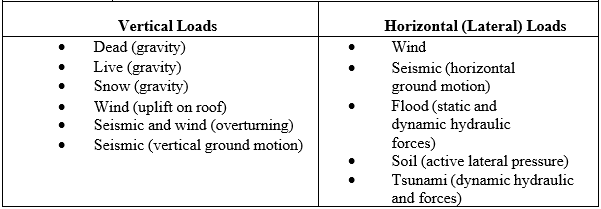
2.3.1 Vertical Loads
Gravity loads act in the same direction as gravity (that is, downward or vertically) and include dead, live, and snow loads. In general, they are static in nature and are usually considered a uniformly distributed or concentrated load. Tributary area is a term often used in design; it is the area of the building construction that is supported by a structural element, including the dead load (that is, weight of the construction) and the live load (that is, any applied loads). For example, the tributary gravity load on a floor joist would include the uniform floor load (dead and live) applied to the area of floor supported by the individual joist. The structural designer
would select a standard beam or column model to analyze bearing connection forces (that is, reactions), internal stresses (that is, bending stresses, shear stresses, axial stresses, and deflection), and stability of the structural member or system (refer to appendix A for beam equations). The selection of an appropriate analytic model, however, is no trivial matter, especially if the structural system departs significantly from traditional engineering assumptions that are based on rigid body and elastic behavior. Such departures from traditional assumptions are particularly relevant to the structural systems that comprise many parts of a house, but to varying degrees.
Wind uplift forces are generated by negative (suction) pressures acting in an outward direction from the surface of the roof in response to the aerodynamics of wind flowing over and around the building. As with gravity loads, the influence of wind uplift pressures on a structure or assembly (that is, roof) is analyzed by using the concepts of tributary areas and uniformly distributed loads. The major differences between wind uplift and gravity loads are that wind pressures act perpendicular to the building surface (usually not in the direction of gravity) and that pressures can vary according to the size of the tributary area and its location on the building, particularly with proximity to changes in geometry (for example, eaves, corners, and ridges). Even though the wind loads are dynamic and highly variable, the design approach is based on a maximum static load (that is, pressure) equivalent.
Vertical forces also are created by overturning reactions that result from wind and seismic lateral loads acting on the overall building and its lateral force-resisting systems (LFRSs). Earthquakes also produce vertical ground motions or accelerations that increase the effect of gravity loads; however, vertical earthquake loads are usually implicitly addressed in the gravity load analysis of a light-frame building.
2.3.2 Lateral Loads
The primary loads that produce lateral forces on buildings are attributable to forces associated with wind, earthquake ground motion, floods, soil, and, although rare, hurricane storm surge and tsunamis. Wind and earthquake lateral loads apply to the entire building. Lateral forces from wind are generated by positive wind pressures on the windward face of the building and by negative pressures on the leeward face of the building, creating a combined push-and-pull effect. Seismic lateral forces are generated by a structure’s dynamic inertial response to ground movement which reverses back and forth in an irregular cyclic motion. The magnitude of the seismic shear (that is, lateral) load depends on the intensity of the ground motion, the building’s mass, and the dynamic response characteristics of the building structure (that is, damping, ductility, stiffness, and so on). For houses and other similar lowrise structures, a simplified seismic load analysis employs equivalent static forces based on fundamental Newtonian mechanics (F = ma, or force = mass x acceleration), with adjustments to account for inelastic, ductile response characteristics of various building systems. Elevating structures on properly designed foundations can minimize flood loads, and avoiding building in a flood plain can eliminate flood loads altogether. Lateral loads from moving water and static hydraulic pressure are substantial. Soil lateral loads apply specifically to foundation wall design, mainly as an “out-of-plane” bending load on the wall.
Lateral loads also produce an overturning moment that must be offset by the dead load and connections of the building. Designers must, therefore, take into consideration the overturning forces on connections designed to restrain components from rotating or the building from overturning. Because wind is capable of generating simultaneous roof uplift and lateral loads, the uplift component of the wind load exacerbates the overturning tension forces that occur because of the lateral component of the wind load. Conversely, the dead load may be sufficient to offset the overturning and uplift forces, as is often the case in lower design wind conditions and in many seismic design conditions.
2.3.3 Structural Systems
As far back as 1948, it was determined that “conventions in general use for wood, steel and concrete structures are not very helpful for designing houses because few are applicable” (NBS, 1948). More specifically, the National Bureau of Standards (NBS, now the National Institute of Standards and Technology) document encouraged the use of more advanced methods of structural analysis for homes. The International Residential Code (IRC; ICC, 2012) has made improvements over the past decade, providing some engineering-based prescriptive solutions for structural designers. These solutions, in turn, allow better consistency in reliability across different components and subassemblies. Most of the prescriptive provisions in the IRC, however, are based on conventional construction (this topic will be discussed in more detail later in this chapter). Difficulties still exist in translating the results of studies of narrowly focused structural systems into general design applications for residential construction.
If a structural member is part of a system, as is typically the case in light- frame residential construction, its response is altered by the strength and stiffness characteristics of the system as a whole. In general, system performance includes two basic concepts known as load sharing and composite action. Load sharing is found in repetitive member systems (that is, wood framing) and reflects the ability of the load on one member to be shared by another or, in the case of a uniform load, the ability of some of the load on a weaker member to be carried by adjacent members. Composite action is found in assemblies of components that, when connected to one another, form a “composite member” with greater capacity and stiffness than the sum of the component parts.
The amount of composite action in a system depends on the manner in which the various system elements are connected. The aim is to achieve a higher effective section modulus than is provided by the individual component members. For example, when floor sheathing is nailed and glued to floor joists, the floor system realizes a greater degree of composite action than a floor with sheathing that is merely nailed; the adhesive between components helps prevent shear slippage, particularly if a rigid adhesive is used. Exact quantification of this result is difficult and beyond the scope of typical residential structural design. Slippage because of shear stresses transferred between the component parts necessitates consideration of partial composite action, which depends on the stiffness of an assembly’s connections. Consideration of the floor as a system of fully composite T-beams, therefore, may lead to an unconservative solution, whereas the typical approach of considering only the floor joist member without taking into account the composite system effect will lead to a conservative design. For this reason, it is customary to consider the partial composite action of a glued-floor system only for computing deformation. Partial composite action is not considered for failure limit states.
This guide addresses the strength-enhancing effect of load sharing and partial composite action when information is available for practical design guidance. Repetitive-member increase factors (also called system factors) for general design have been quantified for a limited number of systems, such as floor systems and wall systems subjected to wind load. These system factors for general design use are necessarily conservative to cover a broad range of conditions. Exact quantification of system effects is a complex issue that would require extensive research, which has yet to be performed.
System effects do not only affect the strength and stiffness of light-frame assemblies (including walls, floors, and roofs). They also alter the classical understanding of how loads are transferred among the various assemblies of a complex structural system, including a complete wood-framed home. For example, floor joists are sometimes doubled under non-load-bearing partition walls because of the added dead load and resulting stresses, determined in accordance with accepted engineering practice. Such practice is based on a conservative assumption regarding the load path and the structural response. That is, the partition wall creates an additional load but is relatively rigid and can also act as a deep beam, particularly when the top and bottom are attached to the ceiling and floor framing, respectively. As the floor is loaded and deflects, the interior wall helps resist the load. In engineered wood design, the reliability of the load path is reasonably known. Engineered wood design often makes simplifying assumptions to limit cost and effort for the designers. These simplifications are typically included because (1) without them, increased engineering cost could exceed construction savings, and (2) analysis tools are not readily available to model complicated three-dimensional structural configurations.
The preceding example of the composite action illustrates occasions where the interaction of separate structural systems or subassemblies results in improved structural response of the floor system such that it is able to carry more dead and live load than if the partition wall were absent. Whole-house assembly testing has demonstrated this effect (Hurst, 1965). Hence, a double joist should not be required under a typical non-load-bearing partition; in fact, a single joist may not even be required directly below the partition, assuming that the floor sheathing is adequately specified to support the partition between the joists. Although this condition cannot yet be duplicated in a standard analytic form conducive to simple engineering analysis, a designer should be aware of the concept when making design assumptions regarding light-frame residential construction.
Over the past 15 years, an increasing number of whole-house tests have been performed to better understand load transfer between components and subassemblies during system response. A comprehensive whole-structure test program was conducted in Australia by the Commonwealth Scientific and Industrial Research Organization (CSIRO) (Foliente et al., 2000a, 2000b; Paevere et al., 2000). Filiatrault et al. (2002) tested a two-story wood-framed house as part of the Consortium of Universities for Research in Earthquake Engineering-California Institute of Technology (CUREE-Caltech) project and later tested a larger two-story wood- framed building (Christovasilis, Filiatrault, and Wanitkorkal, 2007; Filiatrault et al., 2010) as part of the NEESWood project. Section 6.2 of the guide provides additional information on an array of whole-house tests conducted around the world.
At this point, consider that the response of a structural system, not just its individual elements, determines the manner in which a structure distributes and resists horizontal and vertical loads. For wood-framed systems, the departure from calculations based on classical engineering mechanics (that is, single members with standard tributary areas and assumed elastic behavior) and simplistic assumptions regarding load path can be substantial.
2.4 Load Path
Loads produce stresses on various systems, members, and connections as load-induced forces are transferred down through the structure to the ground. The path through which loads are transferred is known as the load path. A continuous load path is capable of resisting and transferring the loads that are realized throughout the structure from the point of load origination down to the foundation.
As noted, the load path in a conventional home may be extremely complex because of the structural configuration and system effects that can result in substantial load sharing, partial composite action, and a redistribution of forces that depart from traditional engineering concepts. In fact, such complexity is an advantage that often goes overlooked in typical engineering analyses.
Further, because interior non-load-bearing partitions typically are neglected in a structural analysis, the actual load distribution will differ from that assumed in an elementary structural analysis. A strict accounting of structural effects would require numerical tools that are not widely available and are potentially too expensive, as mentioned previously. To the extent possible, a designer should consider system effects, recognizing that inherent uncertainties exist that may make the results imprecise.
2.4.1 Vertical Load Path
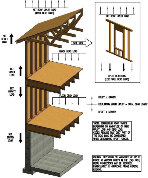
Figures 2.1 and 2.2 illustrate vertically oriented loads created, respectively, by gravity and wind uplift. The wind uplift load originates on the roof from suction forces that act perpendicular to the exterior surface of the roof, as well as from internal pressure acting perpendicular to the interior surface of the roof-ceiling assembly in an outward direction. In addition, overturning forces resulting from lateral wind or seismic forces create vertical uplift loads (not shown in figure 2.2). In fact, a separate analysis of the lateral load path usually addresses overturning forces, necessitating separate overturning connections for buildings located in high-hazard wind or seismic areas (see section 2.3). As addressed in chapter 6, combining these vertical forces and designing a simple load path to accommodate wind uplift and overturning forces simultaneously may be feasible.
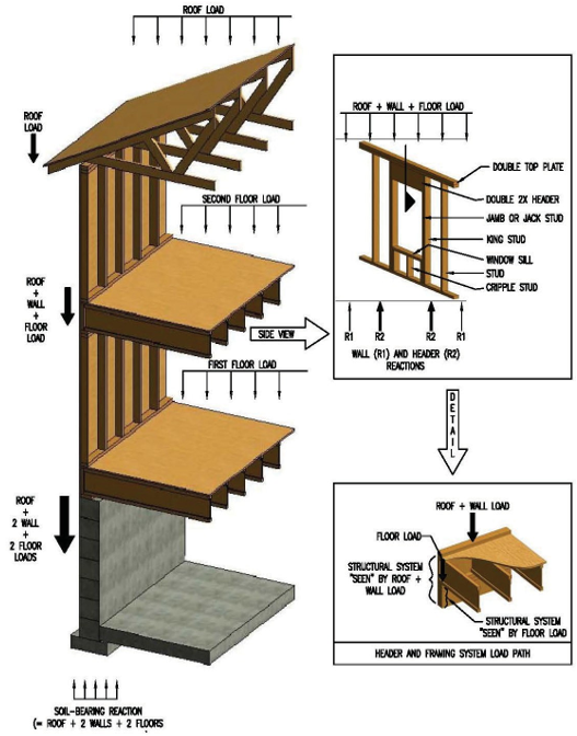
In a typical two-story home, the load path for gravity loads and wind uplift involves the following structural elements—
- Roof
- Roof sheathing
- Roof framing member (rafter or truss).
- Roof-to-wall
- Second-story wall components (top plate, studs, sole plate, headers, wall sheathing, and their interconnections).
- Second-story-wall-to-second-floor
- Second-story-to-first-story-wall
- First-story wall components (same as second story).
- First-story-wall-to-first-story or foundation
- First-story-to-foundation
- Foundation
The preceding list makes obvious that numerous members, assemblies, and connections must be considered when tracking the gravity and wind uplift load paths in a typical wood-framed home. The load path itself is complex, even for elements such as headers that are generally considered simple beams. Usually, the header is part of a structural system (see figure 2.1), not an individual element single-handedly resisting the entire load originating from above. A framing system around a wall opening, not just a header, constitutes a load path.
Figure 2.1 also demonstrates the need for appropriately considering the combination of loads as the load moves “down” the load path. Elements that experience loads from multiple sources (for example, the roof and one or more floors) can be significantly overdesigned if design loads are not proportioned or reduced to account for the improbability that all loads will occur at the same time. Of course, the dead load is always present, but the live loads are transient; even when one floor load is at its lifetime maximum, the others will likely be at only a fraction of their design load. Current design load standards generally allow for multiple transient load reductions; however, with multiple transient load-reduction factors intended for general use, those standards may not effectively address conditions relevant to a specific type of construction (that is, residential).
Consider the soil-bearing reaction at the bottom of the footing in figure 2.1. As implied by the illustration, the soil-bearing force is equivalent to the sum of all tributary loads, dead and live. However, it is important to understand the combined load in the context of design loads. Floor design live loads are based on a lifetime maximum estimate for a single floor in a single level of a building, but the occupancy conditions on the upper and lower stories in homes typically differ. When one load is at its maximum, the other is likely to be at a fraction of its maximum. Designers are able to consider the live loads of the two floors as separate transient loads; specific guidance is available in ASCE 7–10 (ASCE, 2010). In concept, the combined live load should be reduced by an appropriate factor, or one of the loads should be set at a point-in-time value that is a fraction of its design live load. For residential construction, the floor design live load is either 30 pounds per square foot (psf; for bedroom areas) or 40 psf (for other areas), although some codes require a design floor live load of 40 psf for all areas. In contrast, average sustained live loads during typical use conditions are about 6 psf (with one standard deviation of 3 psf), which is about 15 to 20 percent of the design live load (Chalk and Corotis, 1980). If actual loading conditions are not rationally considered in a design, the result may be excessive footing widths, header sizes, and so forth.
When tracking the wind uplift load path (figure 2.2), the designer must consider the offsetting effect of the dead load as it increases down the load path. Building codes and design standards, however, do not permit the consideration of any part of the sustained live load in offsetting wind uplift, even though some minimum point-in-time value of floor live load is likely present if the building is in use—that is, furnished or occupied. In addition, other “nonengineered” load paths, such as those provided by interior walls and partitions, are not typically considered. Although these are prudent limits, they help explain why certain structures may not “calculate” but otherwise perform adequately.
Building codes commonly consider only 0.6 of the dead load when analyzing a structure’s net wind uplift forces. The 0.6 factor is a way of preventing the potential error of requiring insufficient connections where a zero uplift value is calculated in accordance with a nominal design wind load (as opposed to the ultimate wind event that is implied by the use of a safety margin for material strength in unison with a nominal design wind speed). Furthermore, building code developers have expressed a concern that engineers might overestimate actual dead loads, which would be conservative when designing members for gravity loads but un conservative when designing members for combined dead and wind loads.
For complicated house configurations, a load of any type may vary considerably at different points in the structure, necessitating a decision of whether to design for the worst case or to accommodate the variations. Often the worst case condition is applied to the entire structure even when only a limited part of the structure is affected. For example, a floor joist or header may be sized for the worst case span and used throughout the structure. The worst case decision is justified only when the benefit of a more intensive design effort is not offset by a significant cost reduction. Another important consideration is the more detailed analysis of various design conditions that usually results from greater construction complexity. Simplification and cost reduction are both important design objectives, but they may often be mutually exclusive. The consideration of system effects in design, as discussed previously, may result in both simplification and cost efficiencies that improve the quality and affordability of the finished product.
One helpful attribute of traditional platform-framed home construction is that the floor and roof gravity loads are typically transferred through bearing points, not connections. Thus, connections may contribute little to the structural performance of homes with respect to vertical loads associated with gravity (that is, dead, live, and snow loads).
By contrast, metal plate-connected roof and floor trusses rely on connections to resist gravity loads, but these engineered components are designed and produced in accordance with a proven standard and are generally highly reliable (TPI, 2007). Indeed, the metal plate-connected wood truss was first conceived in Florida in the 1950s to respond to the need for improved roof structural performance, particularly with respect to connections in roof construction (Callahan, 2002).
In high-wind climates, where the design wind uplift load approaches offsetting the actual dead load, the consideration of connection design in wood-framed assemblies becomes critical for roofs, walls, and floors (the dead load used to offset wind uplift is the actual dead load, not the design dead load). In fact, the importance of connections in conventionally built homes is evidenced by the common loss of weakly attached roof sheathing or roofs in extreme wind events, such as moderate- to large-magnitude hurricanes.
Newer prescriptive code provisions have addressed many of the historic structural wind damage problems by specifying more stringent general requirements (AWC, 2012; ICC, 2012). In many cases, the newer high-wind prescriptive construction requirements may be improved by more efficient site-specific design solutions that consider wind exposure and system effects and that include other analytic improvements. Site-specific design solutions may also improve prescriptive seismic provisions in the latest building codes for conventional residential construction (ICC, 2012).
2.4.2 Lateral Load Path
The overall system that provides lateral resistance and stability to a building is known as the LFRS. In light-frame construction, the LFRS includes shear walls and horizontal diaphragms. Shear walls are walls that are typically braced or clad with structural sheathing panels to resist racking forces. Horizontal diaphragms are floor and roof assemblies that are also usually clad with structural sheathing panels. Although more complicated and difficult to visualize, the lateral forces imposed on a building from wind or seismic action also follow a load path that distributes and transfers shear and overturning forces from lateral loads. The lateral loads of primary interest are those resulting from—
- The horizontal component of wind pressures on the building’s exterior surface area.
- The inertial response of a building’s mass and structural system to earthquake ground motions.
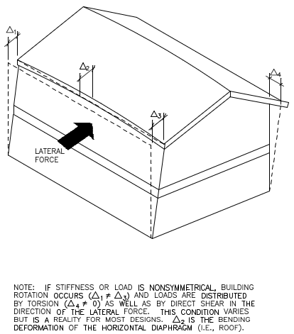
As seen in figure 2.3, the lateral load path in wood-framed construction involves entire structural assemblies (that is, walls, floors, and roofs) and their interconnections, not just individual elements or frames, as would be the case with typical steel or concrete buildings that use discrete braced framing systems. The distribution of loads in figure 2.3’s three-dimensional load path depends on the relative stiffness of the various components, connections, and assemblies that constitute the LFRS. To complicate the problem further, stiffness is difficult to determine because of the nonlinearity of the load-displacement characteristics of wood-framed assemblies and their interconnections. Figure 2.4 illustrates a deformed light-frame building under lateral load (the deformations are exaggerated for conceptual purposes). Note, however, that American Society of Civil Engineers (ASCE) 7 (ASCE, 2010) does not require that torsion be included for wind load analyses for light-frame construction that is two stories or less; it is required only in seismic analyses.
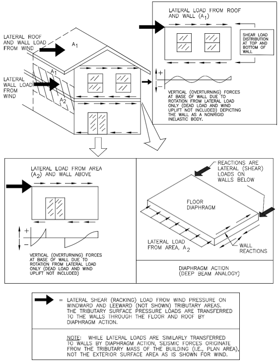
Lateral forces from wind and seismic loads also create overturning forces that cause a “tipping” or “rollover” effect. When these forces are resisted, a building is prevented from overturning in the direction of the lateral load. On a smaller scale, overturning forces are also realized at the shear walls of the LFRS such that the shear walls must be restrained from rotating or rocking on their base by proper connection. This is often done with anchor bolts or hold down hardware. On an even smaller scale, the forces are realized in the individual shear wall segments between openings in the walls.
The overturning force diagrams in Figure 2.3 are based on conventionally built homes constructed without hold-down devices positioned to restrain shear wall segments independently. It should be noted that the effect of dead loads that may offset the overturning force and of wind uplift loads that may increase the overturning force is not necessarily depicted in Figure 2.3’s conceptual plots of overturning forces at the base of the walls. If rigid steel hold-down devices are used in designing the LFRS, the wall begins to behave in a manner similar to a rigid body at the level of individual shear wall segments, particularly when the wall is broken into discrete segments as a result of the configuration of openings in a wall line.
Significant judgment and uncertainty attend the design process for determining building loads and resistance, including definition of the load path and the selection of suitable analytic methods. This guide is intended to serve as a resource for designers who are considering the use of alternative analytic methods when current approaches may not adequately address the design issue.
2.5 Structural Reliability
Before addressing the “nuts and bolts” of the structural design of single- family dwellings, one must understand the fundamental concept of structural reliability. Although safety is generally based on the rational principles of risk and probability theory known as structural reliability, it is also subject to some level of judgment, particularly the experience and understanding of those who participate in the development of building codes and design standards. Slight differences exist in the various code-approved sources for design loads, load combinations, load factors, and other features that can affect structural safety. National load and material design standards, however, have established a consistent basis for safety in structural design. It should be noted that residential occupancies are considered in the establishment of loads. Most importantly, the aim of any design approach is to ensure that the probability of failure (that is, load exceeding resistance) is acceptably small or, conversely, that the level of reliability is sufficiently high.
A common misconception is that design loads alone determine the amount of “safety” achieved in a design. For example, a typical conclusion reached in the aftermath of Hurricane Andrew was that the storm’s wind speed exceeded the design wind speed map value; therefore, the wind map (used as the source for the design load) was perceived to be insufficient. In other cases, such as the Northridge Earthquake, reaction to various anecdotal observations resulted in increased safety factors for certain materials (that is, wood design values were decreased by 25 percent by the City of Los Angeles). In reality, numerous factors affect the level of reliability in a structural system, just as several factors determine the level of performance realized by buildings in a single extreme event, such as Hurricane Andrew or the Northridge Earthquake.
Structural reliability is a multifaceted performance goal that integrates all objective and subjective aspects of the design process, including the following major variables—
- Determination of characteristic material or assembly strength values based on tested material properties and their variabilities.
- Application of a nominal or design load based on a statistical representation of load data and the data’s uncertainty or variability.
- Consideration of various uncertainties associated with the design practice (for example, competency of designers and accuracy of analytic approaches), the construction practice (for example, quality or workmanship), and durability.
- Selection of a level of reliability that considers the preceding factors and the consequences of exceeding a specified design limit state (that is, collapse, deformation, or the onset of “unacceptable” damage).
When the aforementioned variables are known or logically perceived, many ways are available to achieve a specified level of safety. As a practical necessity, however, the design process has been standardized to provide a reasonably consistent basis for applying the following key elements of the design process—
- Characterizing strength properties for various material types (for example, steel, wood, concrete, and masonry).
- Defining nominal design loads and load combinations for crucial inputs into the design process.
- Conveying an acceptable level of safety (that is, a safety margin) that can be easily and consistently applied by designers.
Institutionalized design procedures provide a basis for selecting from the vast array of structural material options available in the construction market. The generalizations necessary to address the multitude of design conditions, however, rely on a simplified and standardized format and thus often overlook special aspects of a particular design application.
The following sections discuss safety, but they are intentionally basic and focus on providing the reader with a conceptual understanding of safety and probability as a fundamental aspect of engineering. Probability concepts are fundamental to modern design formats, such as load and resistance factor design (LRFD), which is also known as reliability-based design or strength design. The same concepts are also crucial to understanding the implications of the simple safety factor in traditional allowable stress design (ASD). In 2002, the Committee on Reliability- Based Design of Wood Structures undertook a special project for the ASCE Structural Engineering Institute (SEI). The objective was to quantify the reliability inherent in AF&PA/ASCE 16 (1996) using state-of-the-art structural reliability methods. The project resulted in a series of papers (Bulleit et al., 2004; Rosowsky et al., 2004; van de Lindt and Rosowsky, 2005). Several years later, the same committee completed another SEI special project that examined the feasibility of applying PBD principles to wood design (see chapter 1) (van de Lindt et al., 2009).
That study addressed both the benefits and the challenges. As discussed previously in this chapter, PBD concepts will be mentioned throughout this guide as an option for the structural designer to improve the performance of residential structures. Following are some additional references.
- Probability Concepts in Engineering Planning and Design. Vol. I, Basic Principles (Ang and Tang, 1975).
- CRC Structural Engineering Handbook. 29, “Structural Reliability” (Chen, 1997).
- Probabilistic Structural Mechanics Handbook: Theory and Industrial Applications (Sundararajan, 1995).
- Uncertainty Analysis, Loads, and Safety in Structural Engineering (Hart, 1982).
- Statistical Models in Engineering (Hahn and Shapiro, 1967).
- Reliability of Structures, 2nd Ed. (Nowak and Collins, 2013).
2.5.1 Nominal Design Loads
Nominal design loads are generally specified on the basis of probability, with the interchangeable terms “return period” and “mean recurrence interval” often used to describe the probability of loads. Either term represents a condition that is predicted to be met or exceeded once, on average, during the reference time period. For design purposes, loads are generally evaluated in terms of annual extremes (that is, the variability of the largest load experienced in any given 1-year period) or maximum lifetime values.
The historical use of safety factors in ASD has generally been based on a 50- year return period design load. With the advent of LRFD, the calculation of nominal loads has shifted away from ASD for some load types. Now, earthquake and wind design use design values represented by hazard levels considered to be ultimate (or LRFD level) events. The Maximum Considered Earthquake is the intensity of ground motion that has the probability of exceedance of 2 percent in 50 years (for example, a 2,500-year return period). Earthquake design loads are based on a 2/3 factor of the ground motion that occurs during the 2,500-year event. They are computed from annual probabilities and design periods and is expressed as P = 1- (1-Pa)n where Pa is the annual probability (1/return period), P is the probability of exceedance during the time period of interest, and n is the time period of interest. This formula is described in the commentary of ASCE 7–10.
ASCE 7–10 (ASCE, 2010) provides risk-targeted seismic design maps for the conterminous United States (Luco et al., 2007). One key result of the move from uniform-hazard to risk-targeted mapped spectral accelerations is a reduction in the design spectral acceleration for the central and eastern United States to 70 to 90 percent of their 2005 values. This reduction occurred because previous mapping considered only the magnitude of the event, not the likely frequency.
The method of determining a design load also differs according to the type of load and the availability of data to evaluate the time-varying nature of loads. The derivation of various nominal loads may be assembled from information and references contained in the ASCE 7 standard (ASCE, 2010). Design wind loads are based on a probabilistic analysis of wind speed data collected from many weather stations across the United States. The data include wind loads in most of the country and hurricane simulation modeling for wind speeds along the hurricane-prone coastlines. The wind speed maps in ASCE 7–10 represent the speeds that have a 7- percent probability of exceedance in 50 years, or a 700-year return period for residential structures (see section 3.6 on wind design). Snow loads are based on snowfall or ground snow depth data and are correlated to roof snow loads through recent studies. Snow drift loads in ASCE 7–10 (ASCE, 2010) have improved from earlier versions of the standard by adding a new thermal factor and by not requiring unbalanced snow loads be applied to hip and gable roofs when the roof slope is steeper than 7 on 12 or is shallower than ½ on 12 (1/2:12).
Earthquake loads are defined from historical ground motion data and conceptualized risk models based on direct or indirect evidence of past earthquake activity. The maps that illustrate the seismic ground motion have been developed by the U.S. Geological Survey. Considerable uncertainty exists in the estimation of seismic hazards, particularly in areas that are believed to have low seismicity (that is, few events) but the potential for major seismic events. Details of the ASCE 7–10 map development can be found in Luco et al. (2007). Floor live loads are modeled by using live load surveys of “point-in-time” loading conditions and hypotheses or judgment concerning extreme or maximum lifetime loads. In some cases, expert panels decide on appropriate loads or related load characteristics when adequate data are not available.
In summary, the determination of load characteristics is based on historical data, risk modeling, and expert opinion. Those factors, in turn, guide the specification of nominal design loads for general design purposes in both the ASD and LRFD formats. It is important to remember that the return period of the design load is not the only factor determining safety; the selection of safety factors (ASD), load factors (LRFD), or performance objectives depends on the definition of a nominal design load (that is, its return period) and the material’s strength characterization to achieve a specified level of safety.
2.5.2 Basic Safety Concepts in Allowable Stress Design
The concept of ASD is demonstrated in a generic design equation or performance function (see equation 2.5-1) for a wood framing member. A common practice in traditional ASD is to divide the characteristic (for example, fifth percentile) material strength value by a safety factor of greater than 1 to determine an allowable design strength that is dependent on a selected limit state (that is, a proportional limit or rupture) and material type, among other factors that involve the judgment of specification-writing groups. Most factors of safety fall in the range of 1.5 to 2.5 for residential design. The allowable design strength is then compared to the stresses created by a nominal design load combination, usually based on a 50-year mean recurrence interval. A lower safety factor is generally applied to design conditions that are less variable or that are associated with a “noncritical” consequence, while the higher safety factor is typically applied to elements associated with greater uncertainty, such as connections. In addition, a higher safety factor is usually selected for materials, systems, or stress conditions that result in an abrupt failure mode without warning. The safety factor is also intended to cover the variability in loads in ASD.
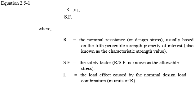
The equation refers to characteristic material strength, which represents the material stress value used for design purposes (also known as nominal or design strength or stress). When characteristic material strength (normalized to standard conditions) is divided by a safety factor, the result is an allowable material strength or stress. Given that materials exhibit variability in their stress capacity (some more variable than others), it is necessary to select a statistical value from the available material test data. Generally, but not always, the test methods, data, and evaluations of characteristic material strength values follow standardized procedures that vary across material industries (for example, concrete, wood, and steel) in part because of the uniqueness of each material. In most cases, the characteristic strength value is based on a lower bound test statistic such as the fifth percentile, which is a value at which no more than 5 percent of the material specimens from a sample exhibit a lesser value. Because sampling is involved, the sampling methodology and sample size become critical to confidence in the characteristic strength value for general design applications.
In some cases, procedures for establishing characteristic material strength values are highly sophisticated and address many of the concerns mentioned previously; in other cases, the process is simple and involves reduced levels of exactness or confidence (for example, use of the lowest value in a small number of tests). Generally, the more variable a material, the more sophisticated the determination of characteristic material strength properties. A good example is the wood industry, whose many species and grades of lumber further complicate the inherent nonhomogeneity of the product. The wood industry, therefore, uses fairly sophisticated procedures to sample and determine strength properties for a multitude of material conditions and properties (see chapter 5).
2.5.3 Basic Safety Concepts in Load and Resistance Factor Design
The LRFD format has been conservatively calibrated to the level of safety represented by past ASD design practice and thus retains a tangible connection with historically accepted norms of structural safety (Ellingwood et al., 1982; Galambos et al., 1982; and others);1 thus, either method achieves a similar level of safety. The LRFD approach, however, uses two factors—one applied to the load and one applied to the resistance or strength property—that permits more consistent treatment of safety across a broader range of design conditions.
Equation 2.5-2 shows, conceptually, the LRFD design format (that is, performance function) and compares a factored characteristic resistance value with a factored nominal load. Thus, for a given hazard condition and given material—and similar to the outcome described in the previous section on ASD— increasing the load factor or decreasing the resistance factor has the effect of increasing the level of safety. Figure 2.5 depicts the variable nature of building loads and resistance and the safety margin relative to design loads and nominal resistance.
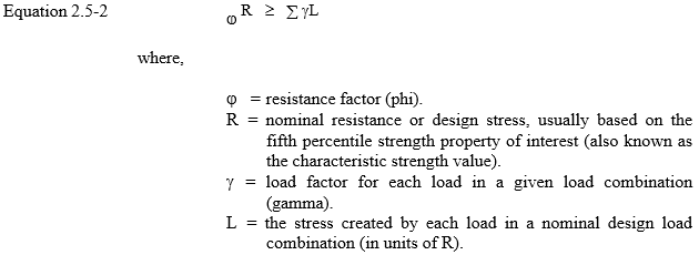
A resistance factor is applied to a characteristic material strength value to account for variability in material strength properties. The resistance factor generally ranges from 0.5 to 0.9, with the lower values applicable to those strength properties that have greater variability or that are associated with an abrupt failure (one with little warning). The resistance factor also depends on the selected characterization of the nominal or characteristic strength value for design purposes (that is, average, lower fifth percentile, lowest value of a limited number of tests, and so on).
A load factor is individually applied to each load in a nominal design load combination to account for the variability and nature of the hazard or combined hazards. It also depends on the selected characterization of the nominal load for design purposes (for example, 50-year return period, 475-year return period, or others). In addition, the load factors proportion the loads relative to each other in a combination of loads (that is, account for independence or correlation between loads and their likely “point-in-time” values when one load assumes a maximum value). Thus, the load factor for a primary load in a load combination is generally 1.0 in LRFD. For other transient loads in a combination, the factors are generally much less than 1. In this manner, the level of safety for a given material and nominal design load is determined by the net effect of factors—one on the resistance side of the design equation and the others on the load side. For ASD, the factors and their purpose are embodied in one simple element the safety factor.
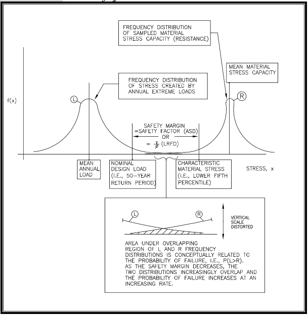
2.5.4 Basic Safety Concepts in Performance-Based Design
PBD is a design approach or methods that allow the designers (or team) to explicitly consider performance objectives during the design process. An ASCE special project, titled “The Next Step for AF&PA/ASCE 16: Performance-Based Design of Wood Structures,” was recently completed (van de Lindt et al., 2009). PBD has been documented for several decades and has its origin in fire engineering, for which the objective is product development that meets a particular prescribed performance, for example, a 1-hour fire rating. Earthquake engineering followed suit with the Structural Engineers Association of California Vision 2000 (1996) document after the 1989 Loma Prieta and 1994 Northridge earthquakes. The primary seismic PBD methodology is described in FEMA P-58, Seismic Performance Assessment of Buildings: Methodology and Implementation (FEMA, 2012). The difference in this design approach is in the consideration of outcomes of the design when a defined hazard level determines the design of the building. Designs based on building codes follow defined criteria in the codes that are intended to provide some level of performance; however, that performance level is never stated and is seldom evaluated except when the building is affected by a design event (FEMA, 2012). Designs based on performance are based on desired outcomes and levels of building performance during and after an event occurs. The beginning points for PBD are the needs of the building owners or stakeholders, not the requirements of the building code.
Although not in widespread use as of this revision of the guide, PBD for wind engineering has been envisioned (van de Lindt and Dao, 2009). Work has begun in wind engineering using as a starting point the process developed for the seismic hazard. The building designs that follow will likely be different for the two hazards, given that seismic designs usually are driven by collapse prevention techniques for extreme events, and wind designs may be driven by preventing weather penetration into the building envelope.
2.5.5 Putting Safety and Performance into Perspective
Safety is a relative measure that must be interpreted in consideration of the many assumptions underlying the treatment of uncertainty in the design process. Any reliable measure of safety must look to past experience and attempt to evaluate historic data in a rational manner to predict the future. Economic consequences are becoming increasingly debated and influential in the development of codified guidelines for structural design, which, as discussed previously, has led to the development of PBD in the seismic arena. Of course, such a design philosophy explicitly considers the performance objectives for a structure.
Implicit consideration of building performance also has been routinely achieved through improved building codes and standards. For example, following Hurricane Charley (2004), the Institute for Business and Home Safety (IBHS) concluded that “enforcement of modern engineering design based building codes made a positive impact on the performance of residential homes during Hurricane Charley in 2004. The frequency of claims was reduced by 60 percent and the claim was 42 percent less severe when a loss did occur, for homes built after the adoption of the modern codes,” (IBHS, 2004: pg. 5). For more information on residential building codes and enforcement, see IBHS (2011). Thus, some engineering requirements in codes may address two very different objectives—life safety and property protection or damage reduction. Finally, the manner in which these two different forms of risk are presented can have a profound impact on the perspective of risk and the perceived need for action or inaction.
Ch. 3 Design Loads for Residential Buildings
3.1 General
Loads are a primary consideration in any building design because they define the nature and magnitude of hazards or external forces that a building must resist to provide reasonable performance (that is, safety and serviceability) throughout the structure’s useful life. The anticipated loads are influenced by a building’s intended use (occupancy and function), configuration (size and shape), and location (climate and site conditions). Ultimately, the type and magnitude of design loads affect critical decisions such as material selection, construction details, and architectural configuration. To optimize the value (that is, performance versus economy) of the finished product, therefore, design loads must be applied realistically.
Although the buildings considered in this guide are primarily single-family detached and attached dwellings, the principles and concepts related to building loads also apply to other similar types of construction, such as low-rise apartment buildings. In general, the design loads recommended in this guide are based on applicable provisions of the ASCE 7 standard– Minimum Design Loads for Buildings and Other Structures (ASCE, 2010). The ASCE 7 standard represents an acceptable practice for building loads in the United States and is recognized in U.S. building codes. For this reason, the reader is encouraged to become familiar with the provisions, commentary, and technical references contained in the ASCE 7 standard.
In general, the structural design of housing has not been treated as a unique engineering discipline or subjected to a special effort to develop better, more efficient design practices. For that reason, this part of the guide focuses on those aspects of ASCE 7 and other technical resources that are particularly relevant to the determination of design loads for residential structures. The guide provides supplemental design assistance to address aspects of residential construction for which current practice is either silent or in need of improvement. The guide’s methods for determining design loads are complete yet tailored to typical residential conditions. As with any design function, the designer must ultimately understand and approve the loads for a given project as well as the overall design methodology, including all its inherent strengths and weaknesses. Because building codes from different jurisdictions can vary in their treatment of design loads, the designer should, as a matter of due diligence, identify variances from both local accepted practice and the applicable building code relative to design loads as presented in this guide, even though the variances may be considered technically sound.
Complete design of a home typically requires the evaluation of several different types of materials, as discussed in chapters 4 through 7. Some material specifications use the allowable stress design (ASD) approach while others use load and resistance factor design (LRFD). Chapter 4 uses the LRFD method for concrete design and the ASD method for masonry design. For wood design, chapters 5, 6, and 7 use ASD. For a single project, therefore, the designer may have to determine loads in accordance with both design formats. This chapter provides load combinations intended for each method. The determination of individual nominal loads is essentially unaffected. Special loads, such as ice loads and rain loads, are not addressed herein. The reader is referred to the ASCE 7 standard and applicable building code provisions regarding special loads.
3.2 Load Combinations
The load combinations in table 3.1 are recommended for use with design specifications based on ASD and LRFD. Load combinations provide the basic set of building load conditions that should be considered by the designer. They establish the proportioning of multiple transient loads that may assume point-in-time values when the load of interest attains its extreme design value. Load combinations are intended as a guide to the designer, who should exercise judgment in any particular application. The load combinations in table 3.1 are appropriate for use with the design loads determined in accordance with this chapter.
The principle used to proportion loads is a recognition that when one load attains its maximum lifetime value, the other loads assume arbitrary point-in-time values associated with the structure’s normal or sustained loading conditions. The advent of LRFD has drawn greater attention to this principle (Ellingwood et al., 1982; Galambos et al., 1982). The proportioning of loads in this chapter for ASD is consistent with design load specifications such as ASCE 7. ASD load combinations found in building codes typically have included some degree of proportioning (that is, D + W + 1/2S) and usually have made allowance for a special reduction for multiple transient loads. Some earlier codes also have permitted allowable material stress increases for load combinations involving wind and earthquake loads. None of these adjustments for ASD load combinations are recommended for use with table 3.1 because the load proportioning is considered sufficient. However, allowable material stress increases that are based upon the duration of the load (that is, wood members under wind loading) may be combined with load proportioning.
Note also that the wind load factor of 1.0 in table 3.1 used for LRFD is consistent with current wind design practice and now recognizes ultimate wind loads when the speeds illustrated in the ASCE 7-10 maps are used. The return period of the design wind speeds for residential buildings along the hurricane-prone coast is now 700 years, and this long return period provides a consistent risk basis for wind design across the country. Many elements of residential design continue to use ASD design level wind speeds, however, primarily because of how products have been tested, rated, and marketed to the industry. Some prescriptive design documents such as the Wood Frame Construction Manual (WFCM) continue to use ASD load combinations in the development of loads provided in the design tables of that document (AWC, 2012). The conversion of LRFD speeds to ASD speeds is ASD speed = LRFD speedx√0.6. The conversion of LRFD pressures to ASD pressures is ASD wind pressure = LRFD pressure x 0.6 (the ASD wind load factor). The load factor changes used in ASCE 7-10 are referenced in the 2012 editions of the building codes where ASCE 7-10 is referenced.
The load combinations in table 3.1 are simplified and tailored to specific application in residential construction and the design of typical components and systems in a home. These or similar load combinations often are used in practice as shortcuts to those load combinations that govern the design result. This guide makes effective use of the shortcuts and demonstrates them in the examples provided later in the chapter. The shortcuts are intended only for the design of residential light-frame construction.
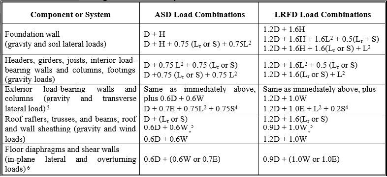
Table 3.1 Notes:
1The load combinations and factors are intended to apply to nominal design loads defined as follows: D = estimated mean dead weight of the construction; E = design earthquake load; H = design lateral pressure for soil condition/type; L = design floor live load; Lr = maximum roof live load anticipated from construction/maintenance;; S = design roof snow load; and W = design wind load. The design or nominal loads should be determined in accordance with this chapter.
2Attic loads may be included in the floor live load, but a 10-psf attic load typically is used only to size ceiling joists adequately for access purposes. If the attic is intended for storage, however, the attic live load (or some portion) should also be considered for the design of other elements in the load path.
3The transverse wind load for stud design is based on a localized component and cladding wind pressure; D + W provides an adequate and simple design check representative of worst-case combined axial and transverse loading. Axial forces from snow loads and roof live loads should usually not be considered simultaneously with an extreme wind load because they are mutually exclusive on residential sloped roofs. Further, in most areas of the United States, design winds are produced by either hurricanes or thunderstorms; therefore, these wind events and snow are mutually exclusive because they occur at different times of the year.
4For walls supporting heavy cladding loads (such as brick veneer), an analysis of earthquake lateral loads and combined axial loads should be considered; however, this load combination rarely governs the design of light-frame construction.
5Wu is wind uplift load from negative (that is, suction) pressures on the roof. Wind uplift loads must be resisted by continuous load path connections to the foundation or until offset by D.
6The 0.6 reduction factor on D is intended to apply to the calculation of net overturning stresses and forces. For wind, the analysis of overturning should also consider roof uplift forces unless a separate load path is designed to transfer those forces.
3.3 Dead Loads
Dead loads consist of the permanent construction material loads comprising the roof, floor, wall, and foundation systems, including claddings, finishes, and fixed equipment. The values for dead loads in table 3.2 are for commonly used materials and constructions in light-frame residential buildings. Dead loads are given as nominal or ASD-level loads. Table 3.3 provides values for common material densities and may be useful in calculating dead loads more accurately. The design examples in section 3.12 demonstrate the straightforward process of calculating dead loads.
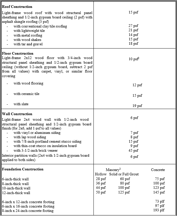
Table 3.2 Notes:
psf = pounds per square foot
1For unit conversions, see appendix B.
2Value also used for roof rafter construction (that is, cathedral ceiling).
3For partially grouted masonry, interpolate between hollow and solid grout in accordance with the fraction of masonry cores that are grouted.
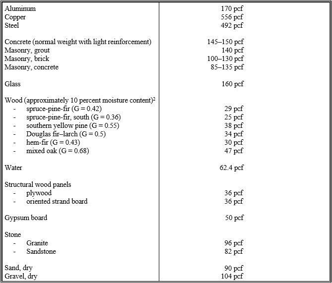
Table 3.3 Notes:
pcf = pounds per cubic foot
1For unit conversions, see appendix B.
2The equilibrium moisture content of lumber is usually not more than 10 percent in protected building construction. The specific gravity, G, is the decimal fraction of dry wood density relative to that of water; therefore, at a 10 percent moisture content, the density of wood is 1.1(G)(62.4 lbs/ft3). The values given are representative of average densities and may easily vary by as much as 15 percent, depending on lumber grade and other factors.
3.4 Live Loads
Live loads are produced by the use and occupancy of a building. Loads include those from human occupants, furnishings, nonfixed equipment, storage, and construction and maintenance activities. Table 3.4 provides recommended design live loads for residential buildings. Live loads also are given as nominal or ASD-level loads. Example 3.1 in section 3.10 demonstrates use of those loads and the load combinations specified in table 3.1, along with other factors discussed in this section. As required to adequately define the loading condition, loads are presented in terms of uniform area loads (in pounds per square foot: psf), concentrated loads (in pounds: lbs), and uniform line loads (in pounds per linear foot: plf). The uniform and concentrated live loads should not be applied simultaneously in a structural evaluation. Concentrated loads should be applied to a small area or surface consistent with the application and should be located or directed to give the maximum load effect possible in end- use conditions. For example, the stair concentrated load of 300 pounds should be applied to the center of the stair tread between supports. The concentrated wheel load of a vehicle on a garage slab or floor should be applied to all areas or members subject to a wheel or jack load, typically using a loaded area of about 20 square inches.
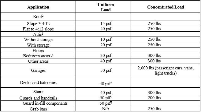
Table 3.4 Notes:
lbs = pounds; plf = pounds per linear foot; psf = pounds per square foot
1Live load values should be verified relative to the locally applicable building code.
2Roof live loads are intended to provide a minimum load for roof design in consideration of maintenance and construction activities. They should not be considered in combination with other transient loads (for example, floor live load, wind load) when designing walls, floors, and foundations. A 15-psf roof live load is recommended for residential roof slopes greater than 4:12; refer to ASCE 7-10 for an alternate approach. 3Loft sleeping and attic storage loads should be considered only in areas with a clear height greater than about 3.5 feet. The concept of a “clear height” limitation on live loads is logical, but it may not be universally recognized.
4Some codes require 40 psf for all floor areas.
5 ASCE 7-10 indicates that this load does not have to be considered for one- and two-family dwellings.
6 The applied normal load on an area is not to exceed 12 in. by 12 in.
7 ASCE 7 requirements may be more stringent.
The floor live load on any given floor area may be reduced in accordance with equation 3.4-1 (Harris, Corotis, and Bova, 1981). Live load reductions also are allowed for multiple floors in ASCE 7-10. The equation applies to floor and support members, such as beams or columns (see table 3-5), which experience floor loads from a total tributary floor area greater than 200 square feet. This equation also is in chapter 4 of ASCE 7-10, which covers live load design.
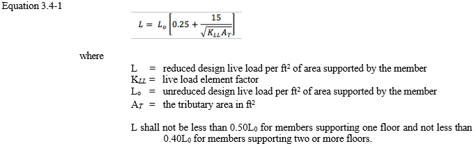
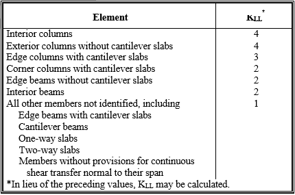
Table 3.5 Note:
Also that the nominal design floor live load in table 3.4 includes both a sustained and a transient load component. The sustained component is that load typically present at any given time and includes the load associated with normal human occupancy and furnishings. For residential buildings, the mean sustained live load is about 6 psf but typically varies from 4 to 8 psf (Chalk and Corotis, 1978). The mean transient live load for dwellings also is about 6 psf but may be as high as 13 psf. A total design live load of 30 to 40 psf is therefore fairly conservative.
3.5 Soil Lateral Loads
The lateral pressure exerted by earth backfill against a residential foundation wall (basement wall) can be calculated with reasonable accuracy on the basis of theory, but only for conditions that rarely occur in practice (Peck, Hanson, and Thornburn, 1974; University of Alberta, 1992). Theoretical analyses usually are based on homogeneous materials that demonstrate consistent compaction and behavioral properties. Such conditions rarely are experienced in typical residential construction projects.
The most common method of determining lateral soil loads on residential foundations follows Rankine’s (1857) theory of earth pressure and uses what is known as the Equivalent Fluid Density (EFD) method. As shown in figure 3.1, pressure distribution is assumed to be triangular and to increase with depth.
In the EFD method, the soil unit weight w is multiplied by an empirical coefficient Ka to account for the soil is not actually fluid and the pressure distribution is not necessarily triangular. The coefficient Ka is known as the active Rankine pressure coefficient. The EFD is determined as shown in equation 3.5-1.
![]()
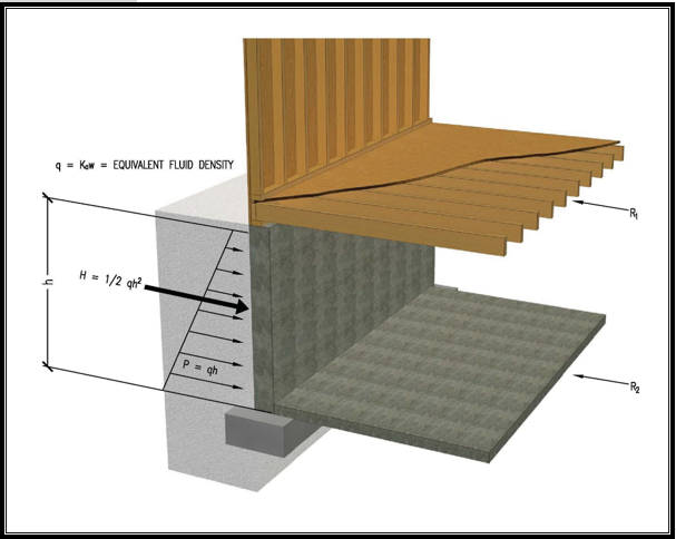
For the triangular pressure distribution shown in figure 3.1, the pressure, P in psf, at depth, h in feet, is determined by equation 3.5-2, and the resultant force, H in lbs, at depth, h in feet, is determined by equation 3.5-3. The factor q is the EFD as discussed above.
![]()
The total active soil force (pounds per linear foot of wall length) is—
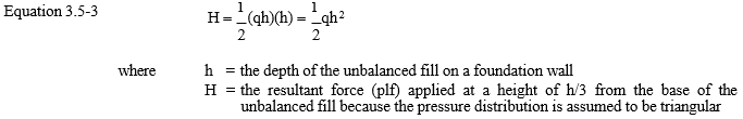
The EFD method is subject to judgment as to the appropriate value of the coefficient Ka. The values of Ka in table 3.6 are recommended for the determination of lateral pressures on residential foundations for various types of backfill materials placed with light compaction and good drainage. Given the long-time use of a 30 pounds per cubic foot (pcf) EFD in residential foundation wall prescriptive design tables (ICC, 2012), the values in table 3.6 may be considered somewhat conservative for typical conditions. A relatively conservative safety factor of 3 to 4 is typically applied to the design of unreinforced or nominally reinforced masonry or concrete foundation walls (ACI, 2011). Therefore, at imminent failure of a foundation wall, the 30 psf design EFD would correspond to an active soil lateral pressure determined by using an EFD of about 90 to 120 pcf or more. The design examples in chapter 4 demonstrate the calculation of soil loads.
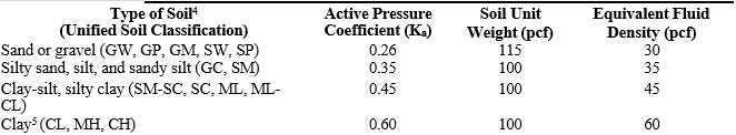
Table 3.6 Notes:
1 Values are applicable to well-drained foundations with less than 10 feet of backfill placed with light compaction or natural settlement, as is common in residential construction. The values do not apply to foundation walls in flood-prone environments; in such cases, an equivalent fluid density value of 80 to 90 pcf would be more appropriate (HUD, 1977).
2 Values are based on the Standard Handbook for Civil Engineers, 3rd ed. (Merritt, 1983), and on research on soil pressures reported in Thin Wall Foundation Testing, Department of Civil Engineering, University of Alberta, (March 1992). The designer should note that the values for soil equivalent fluid density differ from those recommended in ASCE 7-10 but are nonetheless compatible with current residential building codes, design practice, and the stated references.
3 These values do not consider the significantly higher loads that can result from expansive clays and the lateral expansion of moist, frozen soil. Such conditions should be avoided by eliminating expansive clays adjacent to the foundation wall and providing for adequate surface and foundation drainage.
4 Organic silts and clays and expansive clays are unsuitable for backfill material.
5 Backfill in the form of clay soils (non-expansive) should be used with caution on foundation walls with unbalanced fill heights greater than 3 to 4 feet and on cantilevered foundation walls with unbalanced fill heights greater than 2 to 3 feet.
Depending on the type and depth of backfill material and the manner of its placement (see table 3.7), common practice in residential construction is to allow the backfill soil to consolidate naturally by providing an additional 3 to 6 inches of fill material. The additional backfill ensures that surface water drainage away from the foundation remains adequate (that is, the grade slopes away from the building). It also helps avoid heavy compaction that could cause undesirable loads on the foundation wall during and after construction. If soils are heavily compacted at the ground surface or compacted in lifts to standard Proctor densities greater than approximately 85 percent of optimum (ASTM, 2012), the standard 30 pcf EFD assumption may be inadequate. In cases in which the backfill supports exterior slabs, patios, stairs, or other items, however, some amount of compaction is required unless the structures are supported on a separate foundation bearing on undisturbed ground.
Some remediation may be necessary in areas that contain marine clay or other expansive soils. In very moist conditions, these soils can place significant lateral loads against foundation walls. The soils may need to be replaced with soil of lower clay content or the moisture levels must be stabilized to reduce excessive lateral pressures.
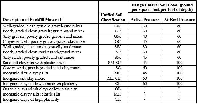
Table 3.7 Notes:
1 Design lateral soil loads are given for moist conditions for the specified soils at their optimum densities. Actual field conditions shall govern.
2 Unsuitable as backfill material
3 The definition and classification of soil materials is in accordance with ASTM D2487.
3.6 Wind Loads
3.6.1 General
Wind produces dynamic loads on a structure at highly variable magnitudes. The variation in pressures at different locations on a building is complex to the point that pressures may become too analytically intensive for precise consideration in design. Wind load specifications attempt to simplify the design problem by considering basic static pressure zones on a building representative of peak loads that are likely to be experienced. The peak pressures in one zone for a given wind direction may not, however, occur simultaneously with peak pressures in other zones. For some pressure zones, the peak pressure depends on a narrow range of wind directions; therefore, the wind directionality effect must also be factored into determining risk-consistent wind loads on buildings. Characteristics of the building site and the surrounding area, such as exposure and topography, also play a large role in determining the peak pressures on the structure and should be carefully considered. In fact, most modern wind load specifications account for wind directionality and other effects in determining nominal design loads in some simplified form (ASCE, 2010). This section further simplifies wind load design specifications to provide an easy yet effective approach for designing typical residential buildings.
Because they vary substantially over the surface of a building, wind loads are considered at two different scales. On a large scale, the loads produced on the overall building are resisted by a system of structural elements working together to transfer the wind loads acting on the entire structure to the ground, a system known as the main wind force-resisting system (MWFRS). The MWFRS of a home includes the shear walls and diaphragms that create the lateral force-resisting system (LFRS) as well as the structural systems, such as trusses, that experience loads from external and internal pressures generated on the building. The wind loads applied to the MWFRS account for the area-averaging effects of time-varying wind pressures on the surface or surfaces of the building.
Wind pressures are greater on certain localized surface areas of the building, particularly near abrupt changes in building geometry (for example, eaves, ridges, and corners). Those higher wind pressures can occur on smaller areas, particularly affecting the loads carried by components and cladding (for example, sheathing, windows, doors, purlins, and studs). The components and cladding (C&C) transfer localized time-varying loads to the MWFRS, at which point the loads average out both spatially and temporally since, at a given time, some components may be at near peak loads while others are at substantially less than peak.
In light-framed wood structural systems, the distinction between MWFRS and C&C is not as clear-cut as in other buildings. In some cases, structural components may act as MWFRS and as C&C, depending on situations. The designer must consider which elements of the building must be treated as C&C, part of the MWFRS, or both. As indicated, parts of the MWFRS that collect and transfer lateral loads in shear walls and floors or roof diaphragms consist of wall studs, sheathing, and trusses, and these elements as a system must be designed for MWFRS lateral loads; but the studs, sheathing, and truss chords must be designed for the direct loading from wind as C&C. Thus, the stud size and connection to top and bottom plates must be designed for C&C pressures, yet the entire wall system, especially the sheathing thickness and the nailing attachment of the sheathing to the studs, must be designed to resist the shear forces created by the lateral loads.
The next section presents a simplified method for determining both MWFRS and C&C wind loads. Because the loads in section 3.6.2 are determined for specific applications, the calculation of MWFRS and C&C wind loads is implicit in the values provided. Design example 3.2 in section 3.12 demonstrates the calculation of wind loads by applying the simplified method in the following section to several design conditions associated with wind loads and the load combinations presented in table 3.1.
3.6.2 Determination of Wind Loads on Residential Buildings
The following method for the design of residential buildings is based on a simplification of the ASCE 7-10 wind provisions (ASCE, 2010); therefore, the wind loads are not exact duplicates. Lateral loads and roof uplift loads are determined by using a projected area approach. Other wind loads are determined for specific components or assemblies that comprise the exterior building envelope. Determining design wind loads on a residential building and its components requires five steps.
Step 1: Determine site design wind speed and basic velocity pressure
From the wind map in figure 3.2 (refer to ASCE 7-10 for a more detailed map for risk category II buildings), select a design wind speed for the site (ASCE, 2010), or, alternatively, find a location-specific wind speed from the local building code office or by using www.atcouncil.org/windspeed. The wind speed map in ASCE 7-10 (figure 3.2) includes the most accurate data and analysis available regarding design wind speeds in the United States. The ASCE 7-10 wind speeds are higher than those used in older design wind maps. The difference results solely from using ultimate wind speeds developed for use with 700-year return periods for risk category II buildings that include residential uses. The speeds correspond to approximately a 7 percent probability of exceedance in 50 years. The design 3- second peak gust wind speeds are 110 to 115 miles per hour (mph) in most of the United States; however, along the hurricane-prone Gulf and Atlantic coasts, the design wind speeds range from 115 to 180 mph. The wind speeds are standardized for exposure C conditions at 33 feet (10 meters). Tornadoes have not been considered in the design wind speeds presented in figure 3.2. Design loads for tornadoes are still in the development stage, and discussion of the latest knowledge is provided in section 3.10.
Once the nominal design wind speed in terms of peak 3-second gust is determined, the designer can select the basic velocity pressure, in accordance with table 3.8. The basic velocity pressure is a reference wind pressure to which coefficients are applied to determine the surface pressures on a building. Velocity pressures in table 3.8 are based on typical conditions for residential construction, namely, suburban terrain (exposure B) and relatively flat or rolling terrain without topographic wind speed-up effects.
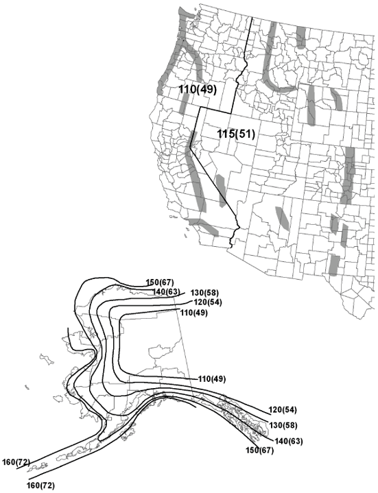

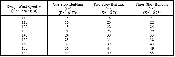
Tables 3.8 Notes:
mph = miles per hour; MWFRS = main wind force-resisting system; psf = pounds per square foot.
1Velocity pressure (psf) equals 0.00256 KD KZV2, where KZ is the velocity pressure exposure coefficient associated with the vertical wind speed profile in suburban terrain (exposure B) at the mean roof height of the building. KD is the wind directionality factor, with a default value of 0.85. All pressures have been rounded to nearest whole psf.
2 To be compliant with ASCE 7-10, a minimum Kz of 0.7 should be applied to determine velocity pressure for one- and two-story buildings in exposure B (suburban terrain) for the design of components and cladding, in exposure B when the envelope procedure is used for the MWFRS, or when designing components and cladding.
Step 2: Adjustments to the basic velocity pressure
If appropriate, the basic velocity pressure from step 1 should be adjusted in accordance with the factors below. The adjustments are cumulative.
Open exposure. The wind pressure values in table 3.8 are based on typical residential exposures to wind (exposure B). If a site is located in generally open, flat terrain with few obstructions to the wind in most directions (exposure C), the designer should multiply the values in table 3.8 by a factor of 1.4. Exposure to a body of water (that is, an ocean or lake) increases wind pressures more because of reduced friction at the surface (exposure D). The values in table 3.8 should be multiplied by a factor of
1.7 to account for this increased pressure for exposure D conditions. The factor may be used to adjust wind loads according to the exposure related to the specific directions of wind approach to the building. The wind exposure conditions used in this guide are derived from ASCE 7-10, and more information about how to determine these exposures is provided in the ASCE 7-10 commentary.
Wind directionality. As noted, the direction of the wind in a given event does not create peak loads (which provide the basis for design pressure coefficients) simultaneously on all building surfaces. In some cases, the pressure zones with the highest design pressures are extremely sensitive to wind direction. In accordance with ASCE 7-10, the velocity pressures in table 3.8 are based on a directionality adjustment of 0.85.
Topographic effects. If topographic wind speed-up effects are likely because a structure is located near the crest of a protruding hill or cliff, the designer should consider using the topographic factor provided in ASCE 7-10. Wind loads can be increased for buildings sited in particularly vulnerable locations relative to topographic features that cause localized wind speed-up for specific wind directions.
The International Residential Code (IRC; ICC 2011) provides a “Simplified Topographic Wind Speed-up Method” for the Kzt factor where required. The simplified method in the IRC is based on the wind speed-up effect for cliff edges, the most vulnerable of the three types of features (hills, ridges or escarpments), and on certain terrain feature heights and dwelling locations. If a more accurate and potentially less conservative determination of an adjusted design wind speed is desired, the designer can apply the ASCE 7-10 provisions for adjusting the wind speed to account for the Kzt factor, where required.
Step 3: Determine lateral wind pressure coefficients
Lateral pressure coefficients in table 3.9 are composite pressure coefficients that combine the effect of positive pressures on the windward face of the building and negative (suction) pressures on the leeward faces of the building. The lateral pressure coefficients are the total effect of the shape factor (Cp) and the gust effect factor (G). When multiplied by the velocity pressure from steps 1 and 2, the selected pressure coefficient provides a single wind pressure that is applied to the vertical projected area of the roof and wall, as indicated in table 3.9. The resulting load is then used to design the home’s LFRS (see chapter 6). The lateral wind load must be determined for the two orthogonal directions on the building (that is, parallel to the ridge and perpendicular to the ridge), using the vertical projected area of the building for each direction. Lateral loads are then assigned to various systems (for example, shear walls, floor diaphragms, and roof diaphragms) by use of tributary areas or other methods described in chapter 6.
This method can be used for determining shear loads because the internal pressures in the building cancel out and do not affect the shear loads. Overturning moments and the design of wall studs and lateral out-of-plane wall loads at the roof-to-wall connection must consider the effects of internal pressure, however; thus, the projected area method is not useful for those calculations. See step 4 for additional information.
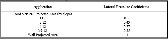
Step 4: Determine wind pressure coefficients for components and assemblies
The pressure coefficients in table 3.9 are derived from ASCE 7-10, based on the assumption that the building is enclosed and not subject to higher internal pressures that may result from a windward opening in the building. Using the values in table 3.9 greatly simplifies the more detailed methodology described in ASCE 7- 10; as a result, some numbers are “rounded.” With the exception of the roof uplift coefficient, all pressures calculated with the coefficients are intended to be applied perpendicular to the building surface area that is tributary to the element of concern; thus, the wind load is applied perpendicular to the actual building surface, not to a projected area. The roof uplift pressure coefficient is used to determine a single wind pressure that may be applied to a horizontal projected area of the roof to determine roof tie-down connection forces.
For buildings in hurricane-prone regions subject to wind-borne debris, the GCp values in table 3.10 are still valid, but the glazed openings in the building must be protected from the possibility of damage by wind-borne debris breaching a wall or roof opening, such as a window or skylight. Past versions of ASCE 7 had allowed design for a “partially enclosed” condition using higher internal pressure coefficients in wind-borne debris regions, but this technique allows a potentially significant amount of wind-driven rain into the building, which would still create a near total economic loss. ASCE 7 no longer allows this design method.
Step 5: Determine design wind pressures
Once the basic velocity pressure is determined in step 1 and adjusted in step 2 for exposure and other site-specific considerations, the designer can calculate the design wind pressures by multiplying the adjusted basic velocity pressure by the pressure coefficients selected in steps 3 and 4. The lateral pressures on the MWFRS are based on coefficients from step 3 and are applied to the tributary areas of the LFRS, such as shear walls and diaphragms. The pressures based on coefficients from step 4 are applied to tributary areas of members such as studs, rafters, trusses, and sheathing to determine stresses in members and forces in connections.
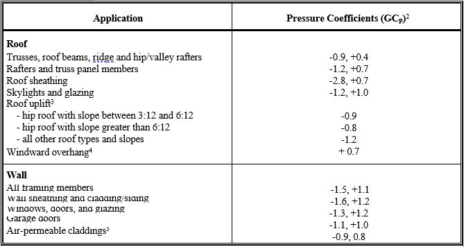
Table 3.10 Notes:
1All coefficients include internal pressure in accordance with the assumption of an enclosed building. With the exception of the categories labeled trusses, roof beams, ridge and hip/valley rafters, and roof uplift, which are based on MWFRS loads, all coefficients are based on component and cladding wind loads.
2Positive and negative signs represent pressures acting inwardly and outwardly, respectively, from the building surface. A negative pressure is a suction or vacuum. Both pressure conditions should be considered to determine the controlling design criteria.
3The roof uplift pressure coefficient is used to determine uplift pressures that are applied to the horizontal projected area of the roof for the purpose of determining uplift tie-down forces. Additional uplift force on roof tie-downs resulting from roof overhangs should also be included. The uplift force must be transferred to the foundation or to a point where it is adequately resisted by the dead load of the building and the capacity of conventional framing connections.
4The windward overhang pressure coefficient is applied to the underside of a windward roof overhang and acts upwardly on the bottom surface of the roof overhang. If the bottom surface of the roof overhang is the roof sheathing, or if the soffit is not covered with a structural material on its underside, then the overhang pressure shall be considered additive to the roof sheathing pressure.
5Air-permeable claddings allow for pressure relief such that the cladding experiences about two-thirds of the pressure differential experienced across the wall assembly (FPL, 1999). Products that experience reduced pressure include lap-type sidings such as wood, vinyl, aluminum, and other similar sidings. Since these components are usually considered “nonessential,” it may be practical to multiply the calculated wind load on any nonstructural cladding by 0.75 to adjust for a serviceability wind load (Galambos and Ellingwood, 1986). Such an adjustment would also be applicable to deflection checks, if required, for other components listed in the table. However, a serviceability load criterion is not included or clearly defined in existing design codes.
3.6.2 Special Considerations in Hurricane-Prone Environments
3.6.2.1 Wind-Borne Debris
The wind loads determined in the previous section assume an enclosed building. If glazing in windows and doors is not protected from wind-borne debris or otherwise designed to resist potential impacts during a major hurricane, a building is more susceptible to structural damage resulting from higher internal pressures that may develop with a windward opening. The potential for water damage to building contents also increases. Openings created in the building envelope during a major hurricane or tornado often are related to unprotected glazing, improperly fastened sheathing, or weak garage doors and their attachment to the building. Section 3.10 discusses tornado design conditions.
In recent years, much attention has been focused on wind-borne debris, based on the results of many damage investigations. Little research has been done to quantify the magnitude or type of debris. The current wind-borne debris protection trigger is wind speed, and the requirement for wind-borne debris protection is all or nothing—meaning that, in accordance with ASCE 7- 10, protection must be provided where design wind speeds are 130 mph and the building is within one mile of the coastal mean high-water line, or anywhere the design wind speed is 140 mph or greater. Conventional practice for wind-borne debris protection in residential construction usually is either impact-resistant shutters installed over glazed openings or impact-resistant glazing. The IRC still permits the use of wood structural panels (plywood or oriented strand board [OSB]) as opening protection for glazing in one- and two-story buildings to resist impacts from wind-borne debris. To use wood structural panels for opening protection, however, attachment hardware is required, with anchors permanently installed on the building. Impact-resistant glazing or protective devices must be tested using an approved test method, such as ASTM E1886 (ASTM, 2005) and ASTM E1996 (ASTM, 2009b).
Just what defines impact resistance and the level of impact risk during a hurricane continues to be the subject of much debate. Surveys of damage following major hurricanes have identified several factors that affect the level of debris impact risk, including
- wind climate (design wind speed);
- exposure (for example, suburban, wooded, height of surrounding buildings);
- development density (that is, distance between buildings);
- construction characteristics (for example, type of roofing, degree of wind resistance); and
- debris sources (for example, roofing, fencing, and gravel).
Current standards for selecting impact criteria for wind-borne debris protection do not explicitly consider all of those factors. Further, the primary debris source in typical residential developments is asphalt roof shingles, clay roof tiles, landscaping materials and driveway gravel, vinyl siding, and vegetation from trees and shrubs, some of which are not represented in existing impact test methods. Recent research has provided insight into performance expectations (Fernandez, Masters, and Gurley, 2010; Masters et al., 2010). These factors have a dramatic effect on the level of wind-borne debris risk. Table 3.11 presents an example of missile types used for current impact tests. Additional factors to consider include emergency egress or access in the event of fire when impact-resistant glazing or fixed shutter systems are specified, potential injury or misapplication during installation of temporary methods of window protection, and durability of protective devices and connection details (including installation quality) such that they themselves do not become a debris hazard over time.
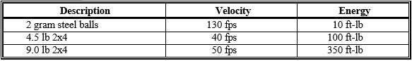
Table 3.11 Notes:
fps = feet per second; ft-lb = foot-pounds; lb = pounds
1Consult ASTM E1886 (ASTM, 2005) for guidance on testing apparatus and methodology.
2These missile types are not necessarily representative of the predominant types or sources of debris at any particular site. The steel balls are intended to represent small gravel that would be commonly used for roof ballast. The 2×4 missiles are intended to represent a direct, end-on blow from construction debris.
Homes that experience wind-borne debris damage may exhibit more catastrophic failures, such as a roof blowoff, but usually this occurs only when large elements of the building envelope fail, such as large windows or garage doors. Wind pressure can also cause failures in these large elements; therefore, in hurricane-prone regions, large windows and garage doors should be specified that meet both wind pressure and wind-borne debris impact requirements, and the attachment of those elements to structural framing should be carefully designed.
One additional element that requires consideration, and for which research is being conducted, is wind-driven rain. Most window manufacturers have products tested to some limitation on water infiltration, and under normal weather conditions those limitations usually are sufficient (usually up to 15 percent of the design wind pressure). Hurricane-force winds will drive rain horizontally and that water can penetrate between window units, under doors, and into soffits and other small places such that, even with attention to this issue, the water can cause significant damage. Both the designer and the builder must pay attention to the construction details at every building joint and every hole in the building envelope to ensure that water penetration during high winds is minimized (Salzano, Masters, and Katsaros, 2010).
3.6.3.2 Tips to Improve Performance
The following design and construction tips are simple considerations for reducing a building’s vulnerability to hurricane wind damage:
- One-story buildings are less vulnerable than two- or three-story buildings to wind damage.
- On average, hip roofs have demonstrated better performance than gable- end roofs.
- Moderate roof slopes (that is, 5:12 to 6:12) tend to optimize the tradeoff between lateral loads and roof uplift loads (that is, they are aerodynamically efficient).
- Roof sheathing installation should be inspected for the proper type and spacing of fasteners, particularly at connections to gable-end framing.
- The installation of metal strapping or other tie-down hardware should be inspected as required to ensure the transfer of uplift loads.
- If composition roof shingles are used, the shingles should be tested in accordance with ASTM D7158 (ASTM, 2011). All roof coverings should be designed or tested and installed to resist the applicable wind loads.
- Glazed-opening protection should be considered in the most severe hurricane-prone areas and in those areas defined as requiring wind-borne debris protection.
- The roof deck may be sealed or a secondary water barrier may be installed on the roof to prevent water infiltration in the event the primary roof covering is blown off. A sealed roof deck can be created by installing minimum 4-inch-wide strips of self-adhering underlayment complying with ASTM D1970 over the roof sheathing joints (ASTM, 2009c). The IRC also contains enhanced underlayment specifications for high-wind regions that require the use of ASTM D226 Type II (30 pound) or equivalent underlayment with a rigorous fastening schedule (ASTM, 2009a).
The HUD document Safer, Stronger Homes (HUD, 2011) includes further details regarding methods for improving the wind hazard resilience of new and existing residential structures.
3.7 Snow Loads
For design purposes, snow typically is treated as a simple uniform gravity load on the horizontal projected area of a roof. The uniformly distributed design snow load on residential roofs can be easily determined by using the unadjusted ground snow load. This simple approach also represents standard practice in some regions of the United States; however, it does not account for a reduction in roof snow load that may be associated with steep roof slopes with slippery surfaces (refer to ASCE 7-10). Drift loads on sloped gable or hip roofs must consider roof slope, warm and cold roof slope factors, and ridge-to-eave distances. ASCE 7-10 has design parameters for each of these snow and roof conditions. Drifting snow has caused numerous roof failures in the past 5 to 10 years. The design guidance in ASCE 7 addresses some of the issues important to consider for drifting snow; for building design, drifting snow must be considered at any building intersection where a roof adjoins a wall or other vertical surface where snow can accumulate. For buildings, snow drifting can occur where a building extension such as a garage or first floor addition adjoins an existing two- story wall. The problem of loading is complicated because snow loads vary with moisture content as well as depth, and depths vary with roof slope, wind speed, and vertical height where drifting can occur.
Design ground snow loads may be obtained from the map in figure 3.3 (for a larger ground snow load map with greater detail, refer to ASCE 7-10); however, snow loads usually are defined by the local building department. Typical ground snow loads range from 0 psf in the southern United States to 50 psf in the northern United States. In mountainous areas, the ground snow load can surpass 100 psf, so local snow data must be carefully considered. The ASCE 7-10 map includes varying ground snow loads with ground elevation above sea level. In areas where the ground snow load is less than 15 psf, the minimum roof live load (refer to section 3.4) usually is the controlling gravity load in roof design.
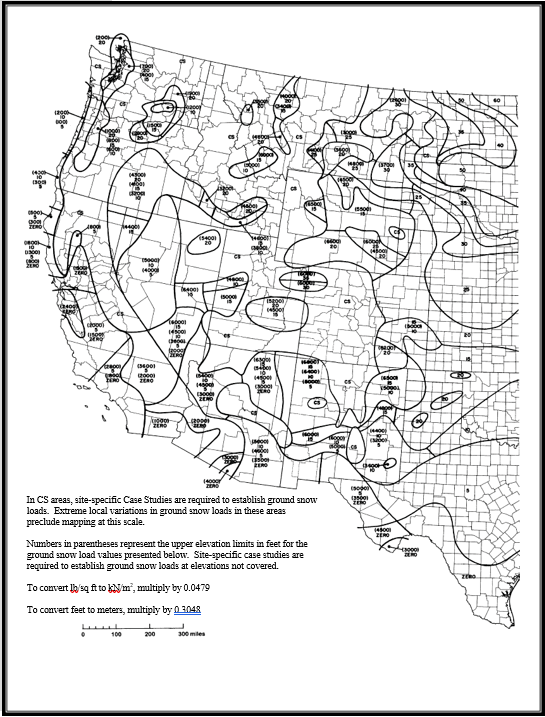
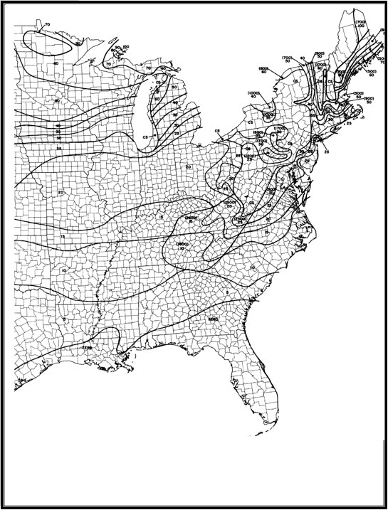
3.8 Earthquake Loads
3.8.1 General
This section provides a simplified earthquake load analysis procedure appropriate for use in residential light-frame construction of not more than three stories above grade. As described in chapter 2, the lateral forces associated with seismic ground motion are based on fundamental Newtonian mechanics (F = ma), expressed in terms of an equivalent static load. The method provided in this section is a simplification of the most current seismic design provisions NEHRP (National Earthquake Hazards Reduction Program) Recommended Seismic Provisions for New Buildings and Other Structures (FEMA, 2009a). The method herein also is similar to a simplified approach found in more recent building codes (ICC, 2012).
In general, wood-framed homes have performed well from a life safety standpoint in major seismic events, probably because of, among other factors, their lightweight and resilient construction, the strength provided by nonstructural systems such as interior walls, and their load distribution capabilities. Wood-framed homes have not performed as well from a damage-reduction standpoint, in part because of brittle finishes such as gypsum board and masonry exteriors, as well as insufficient anchorage of wall framing to foundations, lack of sheathing on cripple walls, and slope failures on hillside sites (HUD, 1994). Garages with wide doors or houses with many large windows on the ground floor can fail as a result of so-called “soft story” or “weak story” behavior because the garage or ground floor walls are much less stiff than the roof or stories above.
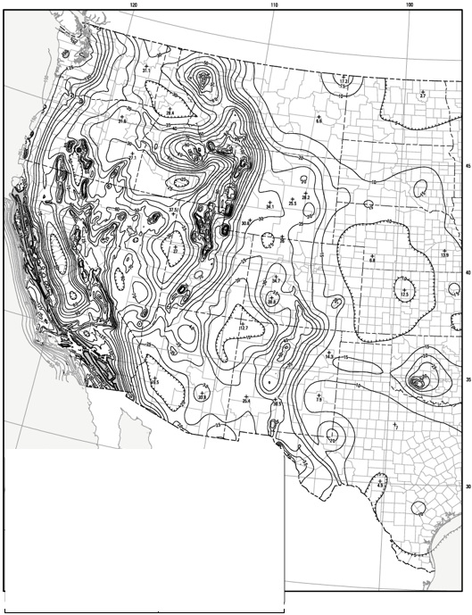
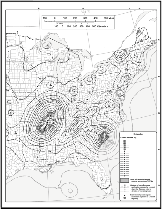
3.8.2 Determination of Earthquake Loads on Houses
The total lateral force at the base of a building is called seismic base shear. The lateral force experienced at a particular story level is called the story shear. The story shear is greatest in the ground story and least in the top story. Seismic base shear and story shear (V) are determined in accordance with the following equation:
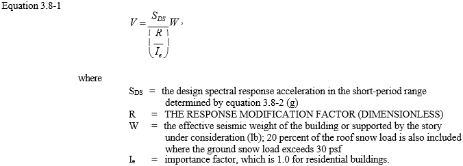
When determining story shear for a given story, the designer attributes to that story one-half of the dead load of the walls on the story under consideration and the dead load supported by the story (dead loads used in determining seismic story shear or base shear are found in section 3.3). For housing, the interior partition wall dead load is reasonably accounted for by the use of a 6 psf load distributed uniformly over the floor area. When applicable, the snow load may be determined in accordance with section 3.7. The inclusion of any snow load, however, is based on the assumption that the snow is always frozen solid and adhered to the building such that it is part of the building mass during the entire seismic event.
The design spectral response acceleration for short-period ground motion SDS typically is used because light-frame buildings such as houses are believed to have a short period of vibration in response to seismic ground motion (that is, high natural frequency). For example, the building tested as part of the NEESWood project in 2006 (Filiatrault et al., 2010) had an elastic period of 0.21 seconds, consistent with the 0.2-second period used to establish the short-period ground motions.
Values of SMS are from figure 3.4. For a larger map with greater detail, refer to ASCE 7-10 or find the response accelerations using the U.S. Geological Survey (USGS) seismic design maps, based on either latitude and longitude or zip codes: http://earthquake.usgs.gov/hazards/designmaps/usdesign.php. The value of SDS should be determined in consideration of the mapped short-period spectral response acceleration SMS and the required soil site amplification factor Fa as follows:
![]()
The value of SMS ranges from practically zero in low-risk areas to 3g in the highest risk regions of the United States. A typical value in high seismic areas is 1.5g. In general, wind loads control the design of the LFRS of light-frame houses when SMS is low.
Table 3.12 provides the values of Fa associated with a standard “firm” soil condition used for the design of residential buildings. Fa decreases with increasing ground motion because the soil begins to dampen the ground motion as shaking intensifies. The soil can therefore have a moderating effect on the seismic shear loads experienced by buildings in high-seismic-risk regions. Dampening also occurs between a building foundation and the soil and thus has a moderating effect. The soil- structure interaction effects on residential buildings have been the topic of little study; therefore, precise design procedures have yet to be developed. If a site is located on fill soils or “soft” ground, a different value of Fa should be considered (see ASCE, 2010, for the full table). Nonetheless, as noted in the Anchorage Earthquake of 1964 and again 30 years later in the Northridge Earthquake, soft soils do not necessarily affect the performance of the aboveground house structure as much as they affect the site and foundations (for example, by settlement, fissuring, or liquefaction).
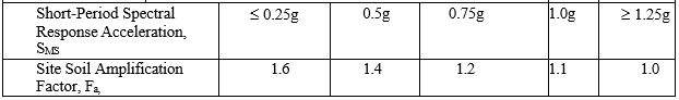
The seismic response factor R has a long history in seismic design but with little in the way of scientific underpinnings until recently (FEMA, 2009b). In fact, the R factor can be traced back to expert opinion in the development of seismic design codes during the 1950s (ATC, 1995). In recognition that buildings can effectively dissipate energy from seismic ground motions through ductile damage, the R factor was conceived to adjust the shear forces from that which would be experienced if a building could exhibit perfectly elastic behavior without some form of ductile energy dissipation (Chopra, 2012).
Those structural building systems that are able to withstand greater ductile damage and deformation without substantial loss of strength are assigned a higher value for R. The R factor also incorporates differences in dampening that are believed to occur for various structural systems. Table 3.13 provides some values for R that are relevant to residential construction. The Quantification of Building Seismic Performance Factors FEMA P-695 (FEMA, 2009b) methodology allows one to develop an R factor for a new LFRS based on the margin against collapse.
The overstrength factor Ω0 addresses the idea that a shear resisting system’s ultimate capacity usually is significantly higher than required by the design load as a result of intended safety margins. Designers incorporate overstrength factors in an attempt to address the principle of balanced design, striving to ensure that components such as connections have sufficient capacity to allow the LFRS to act in its intended ductile manner. These factors are applied at the load combination stage of force development.
The deflection amplification factor Cd is applied to adjust the deflection of story drift, which is determined by use of the seismic shear load as adjusted downward by the R factor. The use of this amplification factor will likely produce a conservative result of expected drift; drift calculations rarely are required in lowrise light-frame buildings because code-required drift limits have not been established for these structure types.
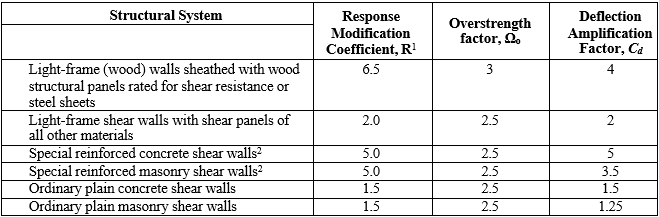
Table 3-13 Notes:
1The R factors may vary for a given structural system type depending on wall configuration, material selection, and connection detailing.
2The wall is reinforced in accordance with concrete design requirements in ACI-318 or ACI-530. Nominally reinforced concrete or masonry that has conventional amounts of vertical reinforcement, such as one #5 rebar at openings and at 4 feet on center, may use the value for reinforced walls, provided the construction is no more than two stories above grade.
Design example 3.3 in section 3.12 demonstrates the calculation of design seismic shear load based on the simplified procedures (the reader is referred to chapter 6 for additional information on seismic loads and analysis).
3.8.3 Seismic Shear Force Distribution
As described in the previous section, the vertical distribution of seismic forces to separate stories on a light-frame building is assumed to be in accordance with the mass supported by each story. The lateral seismic force, Fx, induced at any level, is determined as
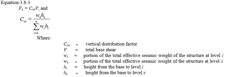
The horizontal distribution of seismic forces to various shear walls on a given story also varies in current practice for light-frame buildings. In chapter 6, several existing approaches to the design of the LFRS of light-frame houses address the issue of horizontal force distribution, with varying degrees of sophistication. Until methods of vertical and horizontal seismic force distribution are better understood for application to light-frame buildings, the importance of designer judgment cannot be overemphasized.
3.8.4 Other Seismic Design Considerations
Perhaps the single most important principle in seismic design is ensuring that the structural components and systems are adequately tied together to perform as a structural unit. Underlying this principle are a host of analytic challenges and uncertainties in actually defining what “adequately tied together” means in a repeatable, accurate, and theoretically sound manner.
Irregularities in the building shape are a key design consideration. Irregularites can occur in plan and in elevation. Plan irregularities can create torsional imbalances, thus requiring designs for moment distribution. Vertical irregularities are often stiffness irregularities, such as “soft stories,” “weak stories,” or “heavy stories.” Sometimes the vertical discontinuities can create unusual distribution of shear between LFRS.
When diaphragms are not flexible, the design should include the inherent torsional moment, Mt, resulting from the location of the structural masses plus the accidental torsional moment, Mta, caused by assumed displacement of the center of mass each way from its actual location by a distance equal to 5 percent of the dimension of the structure perpendicular to the direction of the applied forces. Overturning must be anticipated in the design, and the structure must be designed to resist such forces. Story drift is computed as the largest difference of the deflections aligned vertically at the top and bottom of the story under consideration. The design story drift at level x is computed as
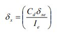
where Cd is the deflection amplification factor from table 3.12, dxe is the deflection at the location of interest determined by elastic analysis, and Ie is the importance factor, which is 1.0 for residential buildings.
For one- and two-story dwellings, the diaphragms are assumed to be flexible. Rigid diaphragms usually are those constructed of concrete or concrete-filled metal deck. ASCE 7- 10 has a set of conditions that are used to determine whether a diaphragm is flexible or rigid. A key issue related to building damage involves deformation compatibility of materials and detailing in a constructed system. This issue may be handled through specification of materials that have similar deformation capabilities or by system detailing that improves compatibility. For example, a relatively flexible hold-down device installed near a rigid sill anchor causes greater stress concentration on the more rigid element, as evidenced by the splitting of wood sill plates in the Northridge Earthquake. The solution can involve increasing the rigidity of the hold-down device (which can lessen the ductility of the system, increase stiffness, and effectively increase seismic load) or redesigning the sill plate connection to accommodate the hold-down deformation and improve load distribution. Researchers in a FEMA-funded CUREE-CalTech project developed a solution for the sill plate connection: a 3-inch-square washer for use on the sill plate anchor bolt. As a nonstructural example of deformation compatibility, gypsum board interior finishes crack in a major seismic event well before the structural capability of the wall’s structural sheathing is exhausted. Conversely, wood exterior siding and similar resilient finishes tend to deform compatibly with the wall and limit unacceptable visual damage (HUD, 1994).
3.9 Flood Loads
A significant level of construction occurs in the nation’s floodplains, so the design professional should be acquainted with the regulations and the design constraints required for building in these areas. The basic design premise for a flood condition is either to elevate the structure above the expected flood level or to build outside the regulatory floodplain. The full explanation of floodplain regulations is beyond the scope of this document; however, the following issues are important for all designers of buildings in floodplains:
- Floodplain regulations are local, so local zoning and/or building codes govern any construction in a floodplain.
- Local ordinances define the regulatory flood elevation, but it usually is the Base Flood Elevation (BFE), defined as the 1-percent annual exceedance probability flood. Frequently the community requires a certain number of feet of freeboard above the BFE to provide a margin of safety.
- The BFE usually is shown on a Flood Insurance Rate Map (FIRM), and this map is available either locally or digitally at FEMA’s Map Service Center.
- Minimum construction standards exist for buildings located in floodplains, and these standards govern elevation of the lowest living floor, the type of foundation that can be constructed, and the materials that can be used below the BFE.
Equations for flood loads are provided in ASCE 7, chapter 5, and for coastal flood conditions, flood formulas are available in FEMA’s Coastal Construction Manual (FEMA, 2011a) or in the United States Army Corps of Engineers Coastal Engineering Manual (USACE, 2009). Details specific to residential construction can be found in FEMA’s Home Builder’s Guide to Coastal Construction (FEMA, 2011b).
ASCE 24, the Flood Resistant Design and Construction standard, also contains significant flood design information. This standard does not include any information about flood loads but does suggest flood elevations for various building occupancies and provides design guidance for building issues from foundations to utilities.
3.10 Tornadoes
A tornado is a narrow, violently rotating column of air that extends from the base of a thunderstorm to the ground. They are the most violent of all atmospheric storms. Tornadoes occur in many parts of the world, but most of them by far occur in the United States, which experiences on average about 1,200 tornadoes per year (NCDC, 2013). Still, a direct tornado strike on a building is a relatively rare event, and the annual probability is lower than for other natural hazard events (that is 1.87E-
4 for a tornado strike of any intensity [Ramsdell et al., 2007] vs. 1.43E-3 for hurricane design wind speeds [ASCE, 2010]). Despite their small size, tornadoes can travel great distances and thus cause destruction to several communities within their path.
Building codes do not provide design guides for tornado loads for two reasons: (1) the rarity of the event and (2) the extreme magnitude of the tornado loads. The media report numerous opinions about whether building codes should cover that type of low probability, high consequence event. Many people believe that it would be economically unfeasible to design houses to resist the expected 200 mph and higher wind speeds produced in tornadoes. Substantial evidence also exists, however, that much damage could be reduced even when communities are struck by extremely violent (EF-4 and EF-5) tornadoes. The Enhanced Fujita (EF) scale is used to classify tornadoes by wind speed, using damage as the indicator of that speed. Examination of damage suggests that such extensive devastation is the result of inadequate structural systems in homes that were not designed for—and are incapable of resisting—any significant wind load. The damage report for a 1970 Lubbock tornado concluded that although the maximum estimated wind speed was 200 mph, the majority of building damage was caused by winds that were only in the 75-to-125 mph range (Mehta et al., 1971).
The interest in developing tornado-resilient design of housing and other structures has gained interest recently following several years (for example, 2011 and
2013) in which violent tornadoes have hit large, densely populated areas. The economic losses attributed to tornadoes since 2000 amount to 15 percent of the economic losses from hurricanes over that same period (NWS, 2013). Despite the low probability of tornado occurrences, the consequences are fairly high when a community is impacted by one of these natural hazard events.
The unique wind loads produced by an extreme tornado (that is, an EF-5 on the Enhanced Fujita scale) well exceed typical design wind loads, particularly in interior portions of the country, where tornadoes are most common but where design wind speeds typically are 115 mph. Most tornadoes, though, are not the most devastating kind; more than 90 percent of all tornadoes are classified as an EF-2 or lower on the EF Scale. Further, detailed analysis of the damage paths of recent violent tornadoes have shown that nearly 90 percent of the damage paths experience wind speeds at or less than the intensity of an EF-2 tornado (Prevatt et al., 2012). Applying the concepts used for hurricane design to buildings located in tornado-prone areas can reduce damage from the lowest wind speed tornadoes.
Tornado loads differ from typical straightline wind events such as hurricanes in that the loads are a superposition of the aerodynamic effects of the wind passing over and around the building and the significant pressure drop within the vortex of the tornado. In combination, these two effects can produce loads on the building in a tornado that are nearly three times higher than those for a straightline wind event with equivalent wind speed (Haan et al, 2010). Many factors affect the magnitude of tornado loads, however, including the tornado size, translation speed, approach angle, and air leakage through the impacted structure. The contributions of each effect have only recently been quantified. As a result, little current information exists for designing structures to survive tornado events. The next version of the commentary on the ASCE 7 standard will likely have some information that will help designers incorporate some level of tornado resistance in their designs. For the most severe events, such as those created by EF-4 or EF-5 tornadoes, a safe room or shelter built to FEMA guidance or ICC standards affords the best life safety protection. ICC 500 (ICC, 2008) is a Standard for the Design and Construction of Storm Shelters; tornado safe room guidance is available in FEMA P-320 (FEMA, 2008b) and community shelter guidance is available in FEMA P-361 (FEMA, 2008a). These safe room and shelter guidance documents and standards have substantial design information about what wind speeds should be used for design and how to modify the wind pressure equation in ASCE 7 to accommodate the differences in the tornado wind structure compared to the hurricane or thunderstorm wind structure.
3.11 Other Load Conditions
In addition to the loads covered in sections 3.3 through 3.10 that are typically considered in the design of a home, other “forces of nature” may create loads on buildings. Some examples include
- frost heave;
- expansive soils; and
- temperature effects.
In certain cases, forces from these phenomena can drastically exceed reasonable design loads for homes. For example, frost heave forces can easily exceed 10,000 psf (Linell and Lobacz, 1980). Similarly, the force of expanding clay soil can be impressive. The self-straining stresses induced by temperature-related expansion or contraction of a member or system that is restrained against movement can be very large, although those stresses are not typically a concern in wood-framed housing.
Sound design detailing is common practice to reduce or eliminate the load increases mentioned. For example, frost heave can be avoided by placing footings below a “safe” frost depth, building on nonfrost-susceptible materials, or using other frost protection methods (see chapter 4). Expansive soil loads can be avoided by isolating building foundations from expansive soil, supporting foundations on a system of deep pilings, and designing foundations that provide for differential ground movements. Temperature effects can be eliminated by providing construction joints that allow for expansion and contraction. Although such temperature effects on wood materials are practically negligible, some finishes, such as ceramic tile, can experience cracking when inadvertently restrained against small movements resulting from variations in temperature.
As noted at the beginning of this chapter, this guide does not address loads from ice, rain, and other exceptional sources. The reader is referred to ASCE 7 and other resources for information regarding special load conditions (ASCE, 2010).