1: Technical Reviews and Audits
1.1 PROGRESS MEASUREMENT
The Systems Engineer measures design progress and maturity by assessing its development at key event-driven points in the development schedule. The design is compared to pre-established exit criteria for the particular event to determine if the appropriate level of maturity has been achieved. These key events are generally known as Technical Reviews and Audits.
A system in development proceeds through a sequence of stages as it proceeds from concept to finished product. These are referred to as “levels of development.” Technical Reviews are done after each level of development to check design maturity, review technical risk, and determines whether to proceed to the next level of development. Technical Reviews reduce program risk and ease the transition to production by:
- Assessing the maturity of the design/development effort,
- Clarifying design requirements,
- Challenging the design and related processes,
- Checking proposed design configuration against technical requirements, customer needs, and system requirements,
- Evaluating the system configuration at different stages,
- Providing a forum for communication, coordination, and integration across all disciplines and IPTs,
- Establishing a common configuration baseline from which to proceed to the next level of design, and
- Recording design decision rationale in the decision database.
Formal technical reviews are preceded by a series of technical interchange meetings where issues, problems and concerns are surfaced and addressed. The formal technical review is NOT the place for problem solving, but to verify problem solving has been done; it is a process rather than an event!
Planning
Planning for Technical Reviews must be extensive and up-front-and-early. Important considerations for planning include the following:
- Timely and effective attention and visibility into the activities preparing for the review,
- Identification and allocation of resources necessary to accomplish the total review effort,
- Tailoring consistent with program risk levels,
- Scheduling consistent with availability of appropriate data,
- Establishing event-driven entry and exit criteria,
- Where appropriate, conduct of incremental reviews,
- Implementation by IPTs,
- Review of all system functions, and
- Confirmation that all system elements are integrated and balanced.
The maturity of enabling products are reviewed with their associated end product. Reviews should consider the testability, producibility, training, and supportability for the system, subsystem or configuration item being addressed.
The depth of the review is a function of the complexity of the system, subsystem, or configuration item being reviewed. Where design is pushing state-of-the-art technology the review will require a greater depth than if it is for a commercial off-the-shelf item. Items, which are complex or an application of new technology, will require a more detailed scrutiny.
Planning Tip: Develop a check list of pre-review, review, and post-review activities required. Develop check lists for exit criteria and required level of detail in design documentation. Include key questions to be answered and what information must be available to facilitate the review process. Figure 1-1 shows the review process with key activities identified.
1.2 TECHNICAL REVIEWS
Technical reviews are conducted at both the system level and at lower levels (e.g., sub-system). This discussion will focus on the primary system-level reviews. Lower-level reviews may be thought of as events that support and prepare for the system-level events. The names used in reference to reviews is unimportant; however, it is important that reviews be held at appropriate points in pro-gram development and that both the contractor and government have common expectations regarding the content and outcomes.
Conducting Reviews
Reviews are event-driven, meaning that they are to be conducted when the progress of the product under development merits review. Forcing a review (simply based on the fact that a schedule developed earlier) projected the review at a point in time will jeopardize the review’s legitimacy. Do the work ahead of the review event. Use the review event as a confirmation of completed effort. The data necessary to determine if the exit criteria are satisfied should be distributed, analyzed, and analysis coordinated prior to the review. The type of information needed for a technical review would include: specifications, drawings, manuals, schedules, design and test data, trade studies, risk analysis, effectiveness analyses, mock-ups, bread-boards, in-process and finished hardware, test methods, technical plans (Manufacturing, Test, Support, Training), and trend (metrics) data. Re-views should be brief and follow a prepared agenda based on the pre-review analysis and assessment of where attention is needed.
Only designated participants should personally attend. These individuals should be those that were involved in the preparatory work for the review and members of the IPTs responsible for meeting the event exit criteria. Participants should include representation from all appropriate government activities, contractor, subcontractors, vendors and suppliers.
A review is the confirmation of a process. New items should not come up at the review. If significant items do emerge, it’s a clear sign the review is being held prematurely, and project risk has just increased significantly. A poorly orchestrated and performed technical review is a significant indicator of management problems.
Action items resulting from the review are documented and tracked. These items, identified by specific nomenclature and due dates, are prepared and distributed as soon as possible after the review. The action taken is tracked and results distributed as items are completed.
Phasing of Technical Reviews
As a system progresses through design and development, it typically passes from a given level of development to another, more advanced level of development. For example, a typical system will pass from a stage where only the requirements are known, to another stage where a conceptual solution has been defined. Or it may pass from a stage where the design requirements for the primary subsystems are formalized, to a stage where the physical design solutions for those requirements are defined. (See Figure 1-2.)
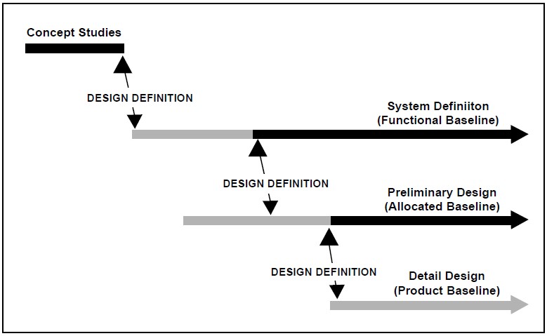
These stages are the “levels of development” referred to in this chapter. System-level technical reviews are generally timed to correspond to the transition from one level of development to an-other. The technical review is the event at which the technical manager verifies that the technical maturity of the system or item under review is sufficient to justify passage into the subsequent phase of development, with the concomitant commitment of resources required.
As the system or product progresses through development, the focus of technical assessment takes different forms. Early in the process, the primary focus is on defining the requirements on which subsequent design and development activities will be based. Similarly, technical reviews conducted during the early stages of development are almost always focused on ensuring that the top-level concepts and system definitions reflect the requirements of the user. Once system-level definition is complete, the focus turns to de-sign at sub-system levels and below. Technical re-views during these stages are typically design re-views that establish design requirements and then verify that physical solutions are consistent with those requirements. In the final stages of development, technical reviews and audits are conducted to verify that the products produced meet the requirements on which the development is based. Figure 1-3 summarizes the typical schedule of system-level reviews by type and focus.
Another issue associated with technical reviews, as well as other key events normally associated with executing the systems engineering process, is when those events generally occur relative to the phases of the DoD acquisition life-cycle process. The timing of these events will vary some-what from program to program, based upon the explicit and unique needs of the situation; how-ever, Figure 1-4 shows a generalized concept of how the technical reviews normal to systems engineering might occur relative to the acquisition life-cycle phases.

Specific system-level technical reviews are known by many different names, and different engineering standards and documents often use different nomenclature when referring to the same review. The names used to refer to technical reviews are unimportant; however, it is important to have a grasp of the schedule of reviews that is normal to system development and to have an understanding of what is the focus and purpose of those reviews. The following paragraphs outline a schedule of reviews that is complete in terms of assessing technical progress from concept through production. The names used were chosen because they seemed to be descriptive of the focus of the activity. Of course, the array of reviews and the focus of individual reviews is to be tailored to the specific needs of the program under development, so not all programs should plan on conducting all of the following reviews.
Alternative Systems Review (ASR)
After the concept studies are complete a preferred system concept is identified. The associated draft System Work Breakdown Structure, preliminary functional baseline, and draft system specification are reviewed to determine feasibility and risk. Technology dependencies are reviewed to ascertain the level of technology risk associated with the proposed concepts. This review is conducted late during the Concept Exploration stage of the Concept and Technology Development Phase of the acquisition process to verify that the preferred system concept:
- Provides a cost-effective, operationally-effective and suitable solution to identified needs,
- Meets established affordability criteria, and
- Can be developed to provide a timely solution to the need at an acceptable level of risk.
The findings of this review are a significant input to decision review conducted after Concept Exploration to determine where the system should enter in the life-cycle process to continue development. This determination is largely based on technology and system development maturity.
It is important to understand that the path of the system through the life-cycle process will be different for systems of different maturities. Consequently, the decision as whether or not to conduct the technical reviews that are briefly described in the following paragraphs is dependent on the extent of design and development required to bring the system to a level of maturity that justifies producing and fielding it.
System Requirements Review (SRR)
If a system architecture system must be developed and a top-down design elaborated, the system will pass through a number of well-defined levels of development, and that being the case, a well-planned schedule of technical reviews is imperative. The Component Advanced Development stage (the second stage of Concept and Technology Development in the revised acquisition life-cycle process) is the stage during which system-level architectures are defined and any necessary advanced development required to assess and control technical risk is conducted. As the system passes into the acquisition process, i.e., passes a Milestone B and enters System Development and Demonstration, it is appropriate to conduct a SRR. The SRR is intended to confirm that the user’s requirements have been translated into system specific technical requirements, that critical technologies are identified and required technology demonstrations are planned, and that risks are well understood and mitigation plans are in place. The draft system specification is verified to reflect the operational requirements.
All relevant documentation should be reviewed, including:
- System Operational Requirements,
- Draft System Specification and any initial draft Performance Item Specifications,
- Functional Analysis (top level block diagrams),
- Feasibility Analysis (results of technology assessments and trade studies to justify system design approach),
- System Maintenance Concept,
- Significant system design criteria (reliability, maintainability, logistics requirements, etc.),
- System Engineering Planning,
- Test and Evaluation Master Plan,
- Draft top-level Technical Performance Measurement, and
- System design documentation (layout drawings, conceptual design drawings, selected supplier components data, etc.).
The SRR confirms that the system-level requirements are sufficiently well understood to permit the developer (contractor) to establish an initial system level functional baseline. Once that baseline is established, the effort begins to define the function-al, performance, and physical attributes of the items below system level and to allocate them to the physical elements that will perform the functions.
System Functional Review (SFR)
The process of defining the items or elements below system level involves substantial engineering effort. This design activity is accompanied by analysis, trade studies, modeling and simulation, as well as continuous developmental testing to achieve an optimum definition of the major elements that make up the system, with associated functionality and performance requirements. This activity results in two major systems engineering products: the final version of the system performance specification and draft versions of the performance specifications, which describe the items below system level (item performance specifications). These documents, in turn, define the system functional baseline and the draft allocated baseline. As this activity is completed, the system has passed from the level of a concept to a well-defined system design, and, as such, it is appropriate to conduct another in the series of technical reviews.
The SFR will typically include the tasks listed below. Most importantly, the system technical description (Functional Baseline) must be approved as the governing technical requirement before proceeding to further technical development. This sets the stage for engineering design and development at the lower levels in the system architecture. The government, as the customer, will normally take control of and manage the system functional baseline following successful completion of the SFR.
The review should include assessment of the following items. More complete lists are found in standards and texts on the subject.
- Verification that the system specification reflects requirements that will meet user expectations.
- Functional Analysis and Allocation of requirements to items below system level,
- Draft Item Performance and some Item Detail Specifications,
- Design data defining the overall system,
- Verification that the risks associated with the system design are at acceptable levels for engineering development,
- Verification that the design selections have been optimized through appropriate trade study analyses,
- Supporting analyses, e.g., logistics, human systems integration, etc., and plans are identified and complete where appropriate,
- Technical Performance Measurement data and analysis, and
- Plans for evolutionary design and development are in place and that the system design is modular and open.
Following the SFR, work proceeds to complete the definition of the design of the items below system level, in terms of function, performance, interface requirements for each item. These definitions are typically captured in item performance specifications, sometimes referred to as prime item development specifications. As these documents are finalized, reviews will normally be held to verify that the design requirements at the item level reflect the set of requirements that will result in an acceptable detailed design, because all design work from the item level to the lowest level in the system will be based on the requirements agreed upon at the item level. The establishment of a set of final item-level design requirements represents the definition of the allocated baseline for the system. There are two primary reviews normally associated with this event: the Software Specification Review (SSR), and the Preliminary Design Review (PDR).
Software Specification Review (SSR)
As system design decisions are made, typically some functions are allocated to hardware items, while others are allocated to software. A separate specification is developed for software items to describe the functions, performance, interfaces and other information that will guide the design and development of software items. In preparation for the system-level PDR, the system software specification is reviewed prior to establishing the Allocated Baseline. The review includes:
- • Review and evaluate the maturity of software requirements,
- Validation that the software requirements specification and the interface requirements specification reflect the system-level requirements allocated to software,
- Evaluation of computer hardware and software compatibility,
- Evaluation of human interfaces, controls, and displays
- Assurance that software-related risks have been identified and mitigation plans established,
- Validation that software designs are consistent with the Operations Concept Document,
- Plans for testing, and
- Review of preliminary manuals.
Preliminary Design Review (PDR)
Using the Functional Baseline, especially the System Specification, as a governing requirement, a preliminary design is expressed in terms of design requirements for subsystems and configuration items. This preliminary design sets forth the functions, performance, and interface requirements that will govern design of the items below system level. Following the PDR, this preliminary design (Allocated Baseline) will be put under formal configuration control [usually] by the contractor. The Item Performance Specifications, including the system software specification, which form the core of the Allocated Baseline, will be confirmed to represent a design that meets the System Specification.
This review is performed during the System Development and Demonstration phase. Reviews are held for configuration items (CIs), or groups of related CIs, prior to a system-level PDR. Item Performance Specifications are put under configuration control (Current DoD practice is for con-tractors to maintain configuration control over Item Performance Specifications, while the government exercises requirements control at the system level). At a minimum, the review should include assessment of the following items:
- Item Performance Specifications,
- Draft Item Detail, Process, and Material Specifications,
- Design data defining major subsystems, equipment, software, and other system elements,
- Analyses, reports, “ility” analyses, trade studies, logistics support analysis data, and design documentation,
- Technical Performance Measurement data and analysis,
- Engineering breadboards, laboratory models, test models, mockups, and prototypes used to support the design, and
- Supplier data describing specific components.
[Rough Rule of Thumb: ~15% of production drawings are released by PDR. This rule is anecdotal and only guidance relating to an “average” defense hardware program.]
Critical Design Review (CDR)
Before starting to build the production line there needs to be verification and formalization of the mutual understanding of the details of the item being produced. Performed during the System Development and Demonstration phase, this re-view evaluates the draft Production Baseline (“Build To” documentation) to determine if the system design documentation (Product Baseline, including Item Detail Specs, Material Specs, Process Specs) is satisfactory to start initial manufacturing. This review includes the evaluation of all CIs. It includes a series of reviews conducted for each hardware CI before release of design to fabrication, and each computer software CI before final coding and testing. Additionally, test plans are reviewed to assess if test efforts are developing sufficiently to indicate the Test Readiness Review will be successful. The approved detail design serves as the basis for final production planning and initiates the development of final software code.
[Rough Rule of Thumb: At CDR the design should be at least 85% complete. Many programs use drawing release as a metric for measuring design completion. This rule is anecdotal and only guidance relating to an “average” defense hardware program.]
Test Readiness Review (TRR)
Typically performed during the System Demonstration stage of the System Development and Demonstration phase (after CDR), the TRR assesses test objectives, procedures, and resources testing coordination. Originally developed as a software CI review, this review is increasingly applied to both hardware and software items. The TRR determines the completeness of test procedures and their compliance with test plans and descriptions. Completion coincides with the initiation of formal CI testing.
Production Readiness Reviews (PRR)
Performed incrementally during the System Development and Demonstration and during the Production Readiness stage of the Production and Deployment phase, this series of reviews is held to determine if production preparation for the system, subsystems, and configuration items is complete, comprehensive, and coordinated. PRRs are necessary to determine the readiness for production prior to executing a production go-ahead decision. They will formally examine the producibility of the production design, the control over the projected production processes, and adequacy of resources necessary to execute production. Manufacturing risk is evaluated in relationship to product and manufacturing process performance, cost, and schedule. These reviews support acquisition decisions to proceed to Low-Rate Initial Production (LRIP) or Full-Rate Production.
Functional Configuration Audit/ System Verification Review (FCA)/(SVR)
This series of audits and the consolidating SVR re-examines and verifies the customer’s needs, and the relationship of these needs to the system and subsystem technical performance descriptions (Functional and Allocated Baselines). They determine if the system produced (including production representative prototypes or LRIP units) is capable of meeting the technical performance requirements established in the specifications, test plans, etc. The FCA verifies that all requirements established in the specifications, associated test plans, and related documents have been tested and that the item has passed the tests, or corrective action has been initiated. The technical assessments and decisions that are made in SVR will be presented to support the full-rate production go-ahead decision. Among the issues addressed:
- Readiness issues for continuing design, continuing verifications, production, training, deployment, operations, support, and disposal have been resolved,
- Verification is comprehensive and complete,
- Configuration audits, including completion of all change actions, have been completed for all CIs,
- Risk management planning has been updated for production,
- Systems Engineering planning is updated for production, and
- Critical achievements, success criteria and metrics have been established for production.
Physical Configuration Audit (PCA)
After full-rate production has been approved, follow-on independent verification (FOT&E) has identified the changes the user requires, and those changes have been corrected on the baseline documents and the production line, then it is time to assure that the product and the product baseline documentation are consistent. The PCA will formalize the Product Baseline, including specifications and the technical data package, so that future changes can only be made through full configuration management procedures. Fundamentally, the PCA verifies the product (as built) is consistent with the Technical Data Package which describes the Product Baseline. The final PCA confirms:
- The subsystem and CI PCAs have been successfully completed,
- The integrated decision database is valid and represents the product,
- All items have been baselined,
- Changes to previous baselines have been completed,
- Testing deficiencies have been resolved and appropriate changes implemented, and
- System processes are current and can be executed.
The PCA is a configuration management activity and is conducted following procedures established in the Configuration Management Plan.
1.3 TAILORING
The reviews described above are based on a complex system development project requiring significant technical evaluation. There are also cases where system technical maturity is more advanced than normal for the phase, for example, where a previous program or an Advanced Technical Concept Demonstration (ACTD) has pro-vided a significant level of technical development applicable to the current program. In some cases this will precipitate the merging or even elimination of acquisition phases. This does not justify elimination of the technical management activities grouped under the general heading of systems analysis and control, nor does it relieve the government program manager of the responsibility to see that these disciplines are enforced. It does, however, highlight the need for flexibility and tailoring to the specific needs of the program under development.
For example, a DoD acquisition strategy that pro-poses that a system proceed directly into the demonstration stage may skip a stage of the complete acquisition process, but it must not skip the formulation of an appropriate Functional Baseline and the equivalent of an SFR to support the development. Nor should it skip the formulation of the Allocated Baseline and the equivalent of a PDR, and the formulation of the Product Baseline and the equivalent of a CDR. Baselines must be developed sequentially because they document different levels of design requirements and must build on each other. However, the assessment of design and development maturity can be tailored as appropriate for the particular system. Tailored efforts still have to deal with the problem of determining when the design maturity should be assessed, and how these assessments will support the formulation and control of baselines, which document the design requirements as the system matures.
In tailoring efforts, be extremely careful determining the level of system complexity. The system integration effort, the development of a single advanced technology or complex sub-component, or the need for intensive software development may be sufficient to establish the total system as a com-plex project, even though it appears simple because most subsystems are simple or off-the-shelf.
2: Trade Studies
2.1 MAKING CHOICES
Trade Studies are a formal decision making methodology used by integrated teams to make choices and resolve conflicts during the systems engineering process. Good trade study analyses demand the participation of the integrated team; otherwise, the solution reached may be based on unwarranted assumptions or may reflect the omission of important data.
Trade studies identify desirable and practical alternatives among requirements, technical objectives, design, program schedule, functional and performance requirements, and life-cycle costs are identified and conducted. Choices are then made using a defined set of criteria. Trade studies are defined, conducted, and documented at the various levels of the functional or physical architecture in enough detail to support decision making and lead to a balanced system solution. The level of detail of any trade study needs to be commensurate with cost, schedule, performance, and risk impacts.
Both formal and informal trade studies are con-ducted in any systems engineering activity. Formal trade studies tend to be those that will be used in formal decision forums, e.g., milestone decisions. These are typically well documented and become a part of the decision database normal to systems development. On the other hand, engineering choices at every level involve trade-offs and decisions that parallel the trade study process. Most of these less-formal studies are documented in summary detail only, but they are important in that they define the design as it evolves.
Systems Engineering Process and Trade Studies
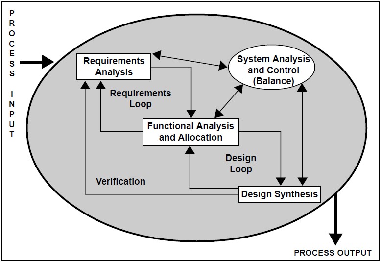
Trade studies are required to support decisions throughout the systems engineering process. During requirements analysis, requirements are balanced against other requirements or constraints, including cost. Requirements analysis trade studies examine and analyze alternative performance and functional requirements to resolve conflicts and satisfy customer needs.
During functional analysis and allocation, functions are balanced with interface requirements, dictated equipment, functional partitioning, requirements flowdown, and configuration items designation considerations. Trade studies are conducted within and across functions to:
- Support functional analyses and allocation of performance requirements and design constraints,
- Define a preferred set of performance requirements satisfying identified functional interfaces,
- Determine performance requirements for lower-level functions when higher-level performance and functional requirements can not be readily resolved to the lower-level, and
- Evaluate alternative functional architectures.
During design synthesis, trade studies are used to evaluate alternative solutions to optimize cost, schedule, performance, and risk. Trade studies are conducted during synthesis to:
- Support decisions for new product and process developments versus non-developmental products and processes;
- Establish system, subsystem, and component configurations;
- Assist in selecting system concepts, designs, and solutions (including people, parts, and materials availability);
- Support materials selection and make-or-buy, process, rate, and location decisions;
- Examine proposed changes;
- Examine alternative technologies to satisfy functional or design requirements including alternatives for moderate- to high- risk technologies;
- Evaluate environmental and cost impacts of materials and processes;
- Evaluate alternative physical architectures to select preferred products and processes; and
- Select standard components, techniques, services, and facilities that reduce system life-cycle cost and meet system effectiveness requirements.
During early program phases, for example, during Concept Exploration and functional baseline development, trade studies are used to examine alternative system-level concepts and scenarios to help establish the system configuration. During later phases, trade studies are used to examine lower-level system segments, subsystems, and end items to assist in selecting component part designs. Performance, cost, safety, reliability, risk, and other effectiveness measures must be traded against each other and against physical characteristics.
2.2 TRADE STUDY BASICS
Trade studies (trade-off analyses) are processes that examine viable alternatives to determine which is preferred. It is important that there be criteria established that are acceptable to all members of the integrated team as a basis for a decision. In addition, there must be an agreed-upon approach to measuring alternatives against the criteria. If these principles are followed, the trade study should produce decisions that are rational, objective, and repeatable. Finally, trade study results must be such that they can be easily communicated to customers and decision makers. If the results of a trade study are too complex to communicate with ease, it is unlikely that the process will result in timely decisions.
Trade Study Process
As shown by Figure 2-1, the process of trade-off analysis consists of defining the problem, bounding the problem, establishing a trade-off method-ology (to include the establishment of decision criteria), selecting alternative solutions, determining the key characteristics of each alternative, evaluating the alternatives, and choosing a solution:
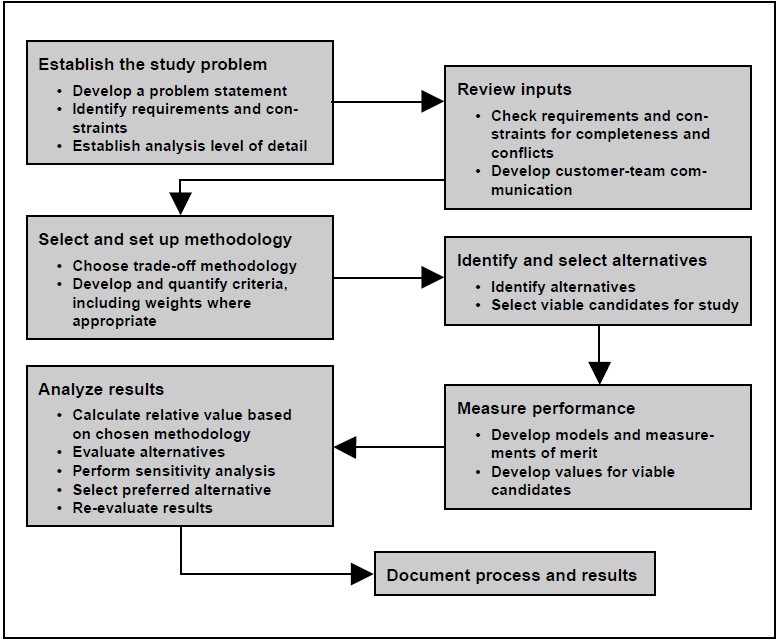
- Defining the problem entails developing a problem statement including any constraints. Problem definition should be done with extreme care. After all, if you don’t have the right problem, you won’t get the right answer.
- Bounding and understanding the problem requires identification of system requirements that apply to the study.
- Conflicts between desired characteristics of the product or process being studied, and the limitations of available data. Available databases should be identified that can provide relevant, historical “actual” information to support evaluation decisions.
- Establishing the methodology includes choosing the mathematical method of comparison, developing and quantifying the criteria used for comparison, and determining weighting factors (if any). Use of appropriate models and methodology will dictate the rationality, objectivity, and repeatability of the study. Experience has shown that this step can be easily abused through both ignorance and design. To the ex-tent possible the chosen methodology should compare alternatives based on true value to the customer and developer. Trade-off relationships should be relevant and rational. Choice of utility or weights should answer the question, “what is the actual value of the increased performance, based on what rationale?”
- Selecting alternative solutions requires identification of all the potential ways of solving the problem and selecting those that appear viable. The number of alternatives can drive the cost of analysis, so alternatives should normally be limited to clearly viable choices.
- Determining the key characteristics entails deriving the data required by the study methodology for each alternative.
- Evaluating the alternatives is the analysis part of the study. It includes the development of a trade-off matrix to compare the alternatives, performance of a sensitivity analysis, selection of a preferred alternative, and a re-evaluation (sanity check) of the alternatives and the study process. Since weighting factors and some “quantified” data can have arbitrary aspects, the sensitivity analysis is crucial. If the solution can be changed with relatively minor changes in data input, the study is probably invalid, and the methodology should be reviewed and revised. After the above tasks are complete, a solution is chosen, documented, and recorded in the database.
Cost Effectiveness Analyses
Cost effectiveness analyses are a special case trade study that compares system or component performance to its cost. These analyses help determine affordability and relative values of alternate solutions. Specifically, they are used to:
- Support identification of affordable, cost optimized mission and performance requirements,
- Support the allocation of performance to an optimum functional structure,
- Provide criteria for the selection of alternative solutions,
- Provide analytic confirmation that designs satisfy customer requirements within cost constraints, and
- Support product and process verification.
3: Modeling and Simulation
3.1 INTRODUCTION
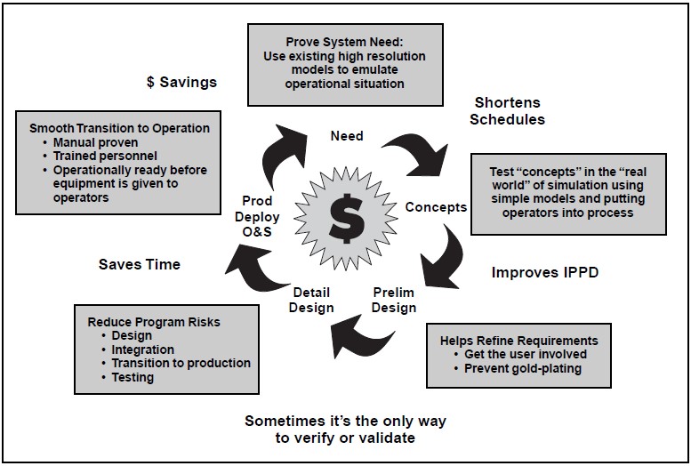
A model is a physical, mathematical, or logical representation of a system entity, phenomenon, or process. A simulation is the implementation of a model over time. A simulation brings a model to life and shows how a particular object or phenomenon will behave. It is useful for testing, analysis or training where real-world systems or concepts can be represented by a model.
Modeling and simulation (M&S) provides virtual duplication of products and processes, and represents those products or processes in readily available and operationally valid environments. Use of models and simulations can reduce the cost and risk of life cycle activities. As shown by Figure 3-1, the advantages are significant throughout the life cycle.
Modeling, Simulation, and Acquisition
Modeling and simulation has become a very important tool across all acquisition-cycle phases and all applications: requirements definition; program management; design and engineering; efficient test planning; result prediction; supplement to actual test and evaluation; manufacturing; and logistics support. With so many opportunities to use M&S, its four major benefits; cost savings, accelerated schedule, improved product quality and cost avoidance can be achieved in any system development when appropriately applied. DoD and industry around the world have recognized these opportunities, and many are taking advantage of the increasing capabilities of computer and information technology. M&S is now capable of prototyping full systems, networks, interconnecting multiple systems and their simulators so that simulation technology is moving in every direction conceivable.
3.2 CLASSES OF SIMULATIONS
The three classes of models and simulations are virtual, constructive, and live:
- Virtual simulations represent systems both physically and electronically. Examples are air-craft trainers, the Navy’s Battle Force Tactical Trainer, Close Combat Tactical Trainer, and built-in training.
- Constructive simulations represent a system and its employment. They include computer models, analytic tools, mockups, IDEF, Flow Diagrams, and Computer-Aided Design/ Manufacturing (CAD/CAM).
- Live simulations are simulated operations with real operators and real equipment. Examples are fire drills, operational tests, and initial production run with soft tooling.
Virtual Simulation
Virtual simulations put the human-in-the-loop. The operator’s physical interface with the system is duplicated, and the simulated system is made to perform as if it were the real system. The operator is subjected to an environment that looks, feels, and behaves like the real thing. The more advanced version of this is the virtual prototype, which allows the individual to interface with a virtual mockup operating in a realistic computer-generated environment. A virtual prototype is a computer-based simulation of a system or subsystem with a degree of functional realism that is comparable to that of a physical prototype.
Constructive Simulations
The purpose of systems engineering is to develop descriptions of system solutions. Accordingly, constructive simulations are important products in all key system engineering tasks and activities. Of special interest to the systems engineer are Computer-Aided Engineering (CAE) tools. Computer-aided tools can allow more in-depth and complete analysis of system requirements early in design. They can provide improved communication be-cause data can be disseminated rapidly to several individuals concurrently, and because design changes can be incorporated and distributed expeditiously. Key computer-aided engineering tools are CAD, CAE, CAM, Continuous Acquisition and Life Cycle Support, and Computer-Aided Systems Engineering:
Computer-Aided Design (CAD). CAD tools are used to describe the product electronically to facilitate and support design decisions. It can model diverse aspects of the system such as how components can be laid out on electrical/electronic circuit boards, how piping or conduit is routed, or how diagnostics will be performed. It is used to lay out systems or components for sizing, positioning, and space allocating using two- or three-dimensional displays. It uses three-dimensional “solid” models to ensure that assemblies, surfaces, intersections, interfaces, etc., are clearly defined. Most CAD tools automatically generate isometric and exploded views of detailed dimensional and assembly drawings, and determine component sur-face areas, volumes, weights, moments of inertia, centers of gravity, etc. Additionally, many CAD tools can develop three-dimensional models of facilities, operator consoles, maintenance work-stations, etc., for evaluating man-machine inter-faces. CAD tools are available in numerous varieties, reflecting different degrees of capabilities, fidelity, and cost. The commercial CAD/CAM product, Computer-Aided Three-Dimensional Interactive Application (CATIA), was used to develop the Boeing 777, and is a good example of current state-of-the-art CAD.
Computer-Aided Engineering (CAE). CAE pro-vides automation of requirements and performance analyses in support of trade studies. It normally would automate technical analyses such as stress, thermodynamic, acoustic, vibration, or heat transfer analysis. Additionally, it can provide automated processes for functional analyses such as fault isolation and testing, failure mode, and safety analyses. CAE can also provide automation of life-cycle-oriented analysis necessary to support the design. Maintainability, producibility, human factor, logistics support, and value/cost analyses are available with CAE tools.
Computer-Aided Manufacturing (CAM). CAM tools are generally designed to provide automated support to both production process planning and to the project management process. Process planning attributes of CAM include establishing Numerical Control parameters, controlling machine tools using pre-coded instructions, programming robotic machinery, handling material, and ordering replacement parts. The production management aspect of CAM provides management control over production-relevant data, uses historical actual costs to predict cost and plan activities, identifies schedule slips or slack on a daily basis, and tracks metrics relative to procurement, inventory, forecasting, scheduling, cost reporting, support, quality, maintenance, capacity, etc. A com-mon example of a computer-based project planning and control tool is Manufacturing Resource Planning II (MRP II). Some CAM programs can accept data direct from a CAD program. With this type of tool, generally referred to as CAD/CAM, substantial CAM data is automatically generated by importing the CAD data directly into the CAM software.
Computer-Aided Systems Engineering (CASE). CASE tools provide automated support for the Systems Engineering and associated processes. CASE tools can provide automated support for integrating system engineering activities, performing the systems engineering tasks outlined in previous chapters, and performing the systems analysis and control activities. It provides technical management support and has a broader capability than either CAD or CAE. An increasing variety of CASE tools are available, as competition brings more products to market, and many of these support the commercial “best Systems Engineering practices.”
Continuous Acquisition and Life Cycle Support (CALS). CALS relates to the application of computerized technology to plan and implement support functions. The emphasis is on information relating to maintenance, supply support, and associated functions. An important aspect of CALS is the importation of information developed during design and production. A key CALS function is to support the maintenance of the system configuration during the operation and support phase. In DoD, CALS supports activities of the logistics community rather than the specific program office, and transfer of data between the CAD or CAM programs to CALS has been problematic. As a result there is current emphasis on development of standards for compatible data exchange. Formats of import include: two- and three-dimensional models (CAD), ASCII formats (Technical Manuals), two-dimensional illustrations (Technical Manuals), and Engineering Drawing formats (Raster, Aperture cards). These formats will be employed in the Integrated Data Environment (IDE) that is mandated for use in DoD program offices.
Live Simulation
Live simulations are simulated operations of real systems using real people in realistic situations. The intent is to put the system, including its operators, through an operational scenario, where some conditions and environments are mimicked to provide a realistic operating situation. Examples of live simulations range from fleet exercises to fire drills.
Eventually live simulations must be performed to validate constructive and virtual simulations. How-ever, live simulations are usually costly, and trade studies should be performed to support the balance of simulation types chosen for the program.
13.3 HARDWARE VERSUS SOFTWARE
Though current emphasis is on software M&S, the decision of whether to use hardware, software, or a combined approach is dependent on the complexity of the system, the flexibility needed for the simulation, the level of fidelity required, and the potential for reuse. Software capabilities are increasing, making software solutions cost effective for large complex projects and repeated processes. Hardware methods are particularly useful for validation of software M&S, simple or one-time projects, and quick checks on changes of pro-duction systems. M&S methods will vary widely in cost. Analysis of the cost-versus-benefits of potential M&S methods should be performed to support planning decisions.
3.4 VERIFICATION, VALIDATION, AND ACCREDITATION
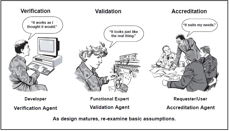
How can you trust the model or simulation? Establish confidence in your model or simulation through formal verification, validation, and accreditation (VV&A). VV&A is usually identified with software, but the basic concept applies to hardware as well. Figure 3-2 shows the basic differences between the terms (VV&A).
More specifically:
- Verification is the process of determining that a model implementation accurately represents the developer’s conceptual description and specifications that the model was designed to.
- Validation is the process of determining the manner and degree to which a model is an ac-curate representation of the real world from the perspective of the intended uses of the model, and of establishing the level of confidence that should be placed on this assessment.
- Accreditation is the formal certification that a model or simulation is acceptable for use for a specific purpose. Accreditation is conferred by the organization best positioned to make the judgment that the model or simulation in question is acceptable. That organization may be an operational user, the program office, or a contractor, depending upon the purposes intended.
VV&A is particularly necessary in cases where:
- Complex and critical interoperability is being represented,
- Reuse is intended,
- Safety of life is involved, and
- Significant resources are involved.
VV&A Currency
VV&A is applied at initial development and use. The VV&A process is required for all DoD simulations and should be redone whenever existing models and simulations undergo a major upgrade or modification. Additionally, whenever the model or simulation violates its documented methodology or inherent boundaries that were used to validate or verify by its different use, then VV&A must be redone. Accreditation, however, may remain valid for the specific application unless revoked by the Accreditation Agent, as long as its use or what it simulates doesn’t change.
3.5 CONSIDERATIONS
There are a number of considerations that should enter into decisions regarding the acquisition and employment of modeling and simulation in defense acquisition management. Among these are such concerns as cost, fidelity, planning, balance, and integration.
Cost Versus Fidelity
Fidelity is the degree to which aspects of the real world are represented in M&S. It is the foundation for development of the model and subsequent VV&A. Cost effectiveness is a serious issue with simulation fidelity, because fidelity can be an aggressive cost driver. The correct balance between cost and fidelity should be the result of simulation need analysis. M&S designers and VV&A agents must decide when enough is enough. Fidelity needs can vary throughout the simulation. This variance should be identified by analysis and planned for.
Note of caution: Don’t confuse the quality of the display with the quality of meeting simulation needs! An example of fidelity is a well-known flight simulator using a PC and simple joystick versus a full 6-degree of freedom fully-instrumented aircraft cockpit. Both have value at different stages of flight training, but obviously vary significantly in cost from thousands of dollars to millions. This cost difference is based on fidelity, or degree of real-world accuracy.
Planning
Planning should be an inherent part of M&S, and, therefore, it must be proactive, early, continuous, and regular. Early planning will help achieve balance and beneficial reuse and integration. With computer and simulation technologies evolving so rapidly, planning is a dynamic process. It must be a continuing process, and it is important that the appropriate simulation experts be involved to maximize the use of new capabilities. M&S activities should be a part of the integrated teaming and involve all responsible organizations. Integrated teams must develop their M&S plans and insert them into the overall planning process, including the TEMP, acquisition strategy, and any other program planning activity.
M&S planning should include:
- Identification of activities responsible for each VV&A element of each model or simulation, and
- Thorough VV&A estimates, formally agreed to by all activities involved in M&S, including T&E commitments from the developmental testers, operational testers, and separate VV&A agents.
Those responsible for the VV&A activities must be identified as a normal part of planning. Figure 3-2 shows the developer as the verification agent, the functional expert as the validation agent, and the user as the accreditation agent. In general this is appropriate for virtual simulations. However, the manufacturer of a constructive simulation would usually be expected to justify or warrantee their program’s use for a particular application. The question of who should actually accomplish VV&A is one that is answered in planning. VV&A requirements should be specifically called out in tasking documents and contracts. When appropriate, VV&A should be part of the contractor’s proposal, and negotiated prior to contract award.
Balance
Balance refers to the use of M&S across the phases of the product life cycle and across the spectrum of functional disciplines involved. The term may further refer to the use of hardware versus soft-ware, fidelity level, VV&A level, and even use versus non-use. Balance should always be based on cost effectiveness analysis. Cost effectiveness analyses should be comprehensive; that is, M&S should be properly considered for use in all parallel applications and across the complete life cycle of the system development and use.
Integration
Integration is obtained by designing a model or simulation to inter-operate with other models or simulations for the purpose of increased performance, cost benefit, or synergism. Multiple benefits or savings can be gained from increased synergism and use over time and across activities. Integration is achieved through reuse or upgrade of legacy programs used by the system, or of the proactive planning of integrated development of new simulations. In this case integration is accomplished through the planned utilization of models, simulations, or data for multiple times or applications over the system life cycle. The planned upgrade of M&S for evolving or parallel uses supports the application of open systems architecture to the system design. M&S efforts that are established to perform a specific function by a specific contractor, subcontractor, or government activity will tend to be sub-optimized. To achieve integration M&S should be managed at least at the program office level.
The Future Direction
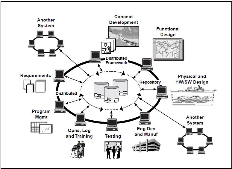
DoD, the Services, and their commands have strongly endorsed the use of M&S throughout the acquisition life cycle. The supporting simulation technology is also evolving as fast as computer technology changes, providing greater fidelity and flexibility. As more simulations are interconnected, the opportunities for further integration expand. M&S successes to date also accelerate its use. The current focus is to achieve open systems of simulations, so they can be plug-and-play across the spectrum of applications. From concept analysis through disposal analysis, programs may use hundreds of different simulations, simulators and model analysis tools. Figure 3-3 shows conceptually how an integrated program M&S would affect the functions of the acquisition process.
A formal DoD initiative, Simulation Based Acquisition (SBA), is currently underway. The SBA vision is to advance the implementation of M&S in the DoD acquisition process toward a robust, collaborative use of simulation technology that is integrated across acquisition phases and programs. The result will be programs that are much better integrated in an IPPD sense, and which are much more efficient in the use of time and dollars expended to meet the needs of operational users.
4: Metrics
4.1 METRICS IN MANAGEMENT
Metrics are measurements collected for the purpose of determining project progress and overall condition by observing the change of the measured quantity over time. Management of technical activities requires use of three basic types of metrics:
- Product metrics that track the development of the product,
- Earned Value which tracks conformance to the planned schedule and cost, and
- Management process metrics that track management activities.
Measurement, evaluation and control of metrics is accomplished through a system of periodic reporting must be planned, established, and monitored to assure metrics are properly measured, evaluated, and the resulting data disseminated.
Product Metrics
Product metrics are those that track key attributes of the design to observe progress toward meeting customer requirements. Product metrics reflect three basic types of requirements: operational performance, life-cycle suitability, and affordability. The key set of systems engineering metrics are the Technical Performance Measurements (TPM.) TPMs are product metrics that track design progress toward meeting customer performance requirements. They are closely associated with the system engineering process because they directly support traceability of operational needs to the design effort. TPMs are derived from Measures of Performance (MOPs) which reflect system requirements. MOPs are derived from Measures of Effectiveness (MOEs) which reflect operational performance requirements.
The term “metric” implies quantitatively measurable data. In design, the usefulness of metric data is greater if it can be measured at the configuration item level. For example, weight can be estimated at all levels of the WBS. Speed, though an extremely important operational parameter, can-not be allocated down through the WBS. It cannot be measured, except through analysis and simulation, until an integrated product is available. Since weight is an important factor in achieving speed objectives, and weight can be measured at various levels as the system is being developed, weight may be the better choice as a metric. It has a direct impact on speed, so it traces to the operational requirement, but, most importantly, it can be allocated throughout the WBS and progress toward achieving weight goals may then be tracked through development to production.
Measures of Effectiveness and Suitability
Measures of Effectiveness (MOEs) and Measures of Suitability (MOSs) are measures of operational effectiveness and suitability in terms of operational outcomes. They identify the most critical performance requirements to meet system-level mission objectives, and will reflect key operational needs in the operational requirements document.
Operational effectiveness is the overall degree of a system’s capability to achieve mission success considering the total operational environment. For example, weapon system effectiveness would con-sider environmental factors such as operator organization, doctrine, and tactics; survivability; vulnerability; and threat characteristics. MOSs, on the other hand, would measure the extent to which the system integrates well into the operation environment and would consider such issues as supportability, human interface compatibility, and maintainability.
Measures of Performance
MOPs characterize physical or functional attributes relating to the execution of the mission or function. They quantify a technical or performance requirement directly derived from MOEs and MOSs. MOPs should relate to these measures such that a change in MOP can be related to a change in MOE or MOS. MOPs should also reflect key performance requirements in the system specification. MOPs are used to derive, develop, support, and document the performance requirements that will be the basis for design activities and process development. They also identify the critical technical parameters that will be tracked through TPMs.
Technical Performance Measurements
TPMs are derived directly from MOPs, and are selected as being critical from a periodic review and control standpoint. TPMs help assess design progress, assess compliance to requirements throughout the WBS, and assist in monitoring and tracking technical risk. They can identify the need for deficiency recovery, and provide information to support cost-performance sensitivity assessments. TPMs can include range, accuracy, weight, size, availability, power output, power required, process time, and other product characteristics that relate directly to the system operational requirements.
TPMs traceable to WBS elements are preferred, so elements within the system can be monitored as well as the system as a whole. However, some necessary TPMs will be limited to the system or subsystem level. For example, the specific fuel consumption of an engine would be a TPM necessary to track during the engine development, but it is not allocated throughout the WBS. It is reported as a single data item reflecting the performance of the engine as a whole. In this case the metric will indicate that the design approach is consistent with the required performance, but it may not be useful as an early warning device to indicate progress toward meeting the design goal. A more detailed discussion of TPMs is available as Supplement A to this chapter.
Example of Measures
MOE: The vehicle must be able to drive fully loaded from Washington, DC, to Tampa on one tank of fuel.
MOP: Vehicle range must be equal to or greater than 1,000 miles.
TPM: Fuel consumption, vehicle weight, tank size, drag, power train friction, etc.
Suitability Metrics
Tracking metrics relating to operational suitability and other life cycle concerns may be appropriate to monitor progress toward an integrated design. Operational suitability is the degree to which a system can be placed satisfactorily in field use considering availability, compatibility, transport-ability, interoperability, reliability, usage rates, maintainability, safety, human factors, documentation, training, manpower, supportability, logistics, and environmental impacts. These suitability parameters can generate product metrics that indicate progress toward an operationally suitable system. For example, factors that indicate the level of automation in the design would reflect progress toward achieving manpower quantity and quality requirements. TPMs and suitability product metrics commonly overlap. For example, Mean Time Between Failure (MBTF) can reflect both effectiveness or suitability requirements.
Suitability metrics would also include measurements that indicate improvement in the producibility, testability, degree of design simplicity, and design robustness. For example, tracking number of parts, number of like parts, and number of wearing parts provides indicators of producibility, maintainability, and design simplicity.
Product Affordability Metrics
Estimated unit production cost can be tracked during the design effort in a manner similar to the TPM approach, with each CI element reporting an estimate based on current design. These estimates are combined at higher WBS levels to provide subsystem and system cost estimates. This provides a running engineering estimate of unit production cost, tracking of conformance to Design-to-Cost (DTC) goals, and a method to isolate design problems relating to production costs.
Life cycle affordability can be tracked through factors that are significant in parametric life cycle cost calculations for the particular system. For example, two factors that reflect life cycle cost for most transport systems are fuel consumption and weight, both of which can be tracked as metrics.
Timing
Product metrics are tied directly to the design process. Planning for metric identification, reporting, and analysis is begun with initial planning in the concept exploration phase. The earliest systems engineering planning should define the management approach, identify performance or characteristics to be measured and tracked, forecast values for those performances or characteristics, deter-mine when assessments will be done, and establish the objectives of assessment.
Implementation is begun with the development of the functional baseline. During this period, systems engineering planning will identify critical technical parameters, time phase planned profiles with tolerance bands and thresholds, reviews or audits or events dependent or critical for achievement of planned profiles, and the method of estimation. During the design effort, from functional to product baseline, the plan will be implemented and continually updated by the systems engineering process. To support implementation, contracts should include provision for contractors to provide measurement, analysis, and reporting. The need to track product metrics ends in the production phase, usually concurrent with the establishment of the product (as built) baseline.
DoD and Industry Policy on Product Metrics
Analysis and control activities shall include performance metrics to measure technical development and design, actual versus planned; and to measure [the extent to which systems meet requirements]. DoD 5000.2-R.
The performing activity establishes and implements TPM to evaluate the adequacy of evolving solutions to identify deficiencies impacting the ability of the system to satisfy a designated value for a technical parameter. EIA IS-632, Section 3.
The performing activity identifies the technical performance measures which are key indicators of system performance…should be limited to critical MOPs which, if not met put the project at cost, schedule, or performance risk. IEEE 1220, Section 6.
4.2 EARNED VALUE
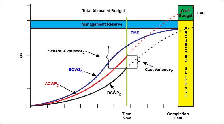
Earned Value is a metric reporting system that uses cost-performance metrics to track the cost and schedule progress of system development against a projected baseline. It is a “big picture” approach and integrates concerns related to performance, cost, and schedule. Referring to Figure 4-1, if we think of the line labeled BCWP (budgeted cost of work performed) as the value that the contractor has “earned,” then deviations from this baseline indicate problems in either cost or schedule. For example, if actual costs vary from budgeted costs, we have a cost variance; if work performed varies from work planned, we have a schedule variance. The projected performance is based on estimates of appropriate cost and schedule to perform the work required by each WBS element. When a variance occurs the system engineer can pinpoint WBS elements that have potential technical development problems. Combined with product metrics, earned value is a powerful technical management tool for detecting and understanding development problems.
Relationships exist between product metrics, the event schedule, the calendar schedule, and Earned Value:
- The Event Schedule includes tasks for each event/exit criteria that must be performed to meet key system requirements, which are directly related to product metrics.
- The Calendar (Detail) Schedule includes time frames established to meet those same product metric-related objectives (schedules).
- Earned Value includes cost/schedule impacts of not meeting those objectives, and, when correlated with product metrics, can identify emerging program and technical risk.
4.3 PROCESS METRICS
Management process metrics are measurements taken to track the process of developing, building, and introducing the system. They include a wide range of potential factors and selection is pro-gram unique. They measure such factors as availability of resources, activity time rates, items completed, completion rates, and customer or team satisfaction.
Examples of these factors are: number of trained personnel onboard, average time to approve/dis-approve ECPs, lines of code or drawings released, ECPs resolved per month, and team risk identification or feedback assessments. Selection of appropriate metrics should be done to track key management activities. Selection of these metrics is part of the systems engineering planning process.
How Much Metrics?
The choice of the amount and depth of metrics is a planning function that seeks a balance between risk and cost. It depends on many considerations, including system complexity, organizational complexity, reporting frequency, how many contractors, program office size and make up, contractor past performance, political visibility, and contract type.
5: Risk Management
5.1 RISK AS REALITY
Risk is inherent in all activities. It is a normal condition of existence. Risk is the potential for a negative future reality that may or may not happen. Risk is defined by two characteristics of a possible negative future event: probability of occurrence (whether something will happen), and consequences of occurrence (how catastrophic if it hap-pens). If the probability of occurrence is not known then one has uncertainty, and the risk is undefined.
Risk is not a problem. It is an understanding of the level of threat due to potential problems. A problem is a consequence that has already occurred.
In fact, knowledge of a risk is an opportunity to avoid a problem. Risk occurs whether there is an attempt to manage it or not. Risk exists whether you acknowledge it, whether you believe it, whether if it is written down, or whether you understand it. Risk does not change because you hope it will, you ignore it, or your boss’s expectations do not reflect it. Nor will it change just because it is contrary to policy, procedure, or regulation. Risk is neither good nor bad. It is just how things are. Progress and opportunity are companions of risk. In order to make progress, risks must be understood, managed, and reduced to acceptable levels.
Types of Risk in a Systems Engineering Environment
Systems engineering management related risks could be related to the system products or to the process of developing the system. Figure 5-1 shows the decomposition of system development risks.
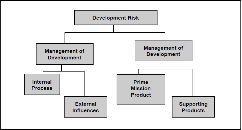
Risks related to the system development generally are traceable to achieving life cycle customer requirements. Product risks include both end product risks that relate to the basic performance and cost of the system, and to enabling products that relate to the products that produce, maintain, support, test, train, and dispose of the system.
Risks relating to the management of the development effort can be technical management risk or risk caused by external influences. Risks dealing with the internal technical management include those associated with schedules, resources, work flow, on time deliverables, availability of appropriate personnel, potential bottlenecks, critical path operations and the like. Risks dealing with external influences include resource availability, higher authority delegation, level of program visibility, regulatory requirements, and the like.
5.2 RISK MANAGEMENT
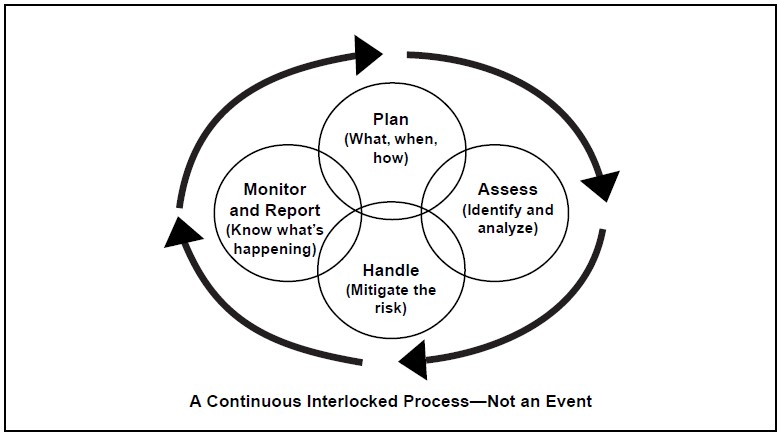
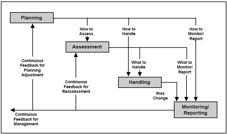
Risk management is an organized method for identifying and measuring risk and for selecting, developing, and implementing options for the handling of risk. It is a process, not a series of events. Risk management depends on risk management planning, early identification and analysis of risks, continuous risk tracking and reassessment, early implementation of corrective actions, communication, documentation, and coordination. Though there are many ways to structure risk management, this course will structure it as having four parts: Planning, Assessment, Handling, and Monitoring. As depicted in Figure 5-2 all of the parts are interlocked to demonstrate that after initial planning the parts begin to be dependent on each other. Illustrating this, Figure 5-3 shows the key control and feedback relationships in the process.
Risk Planning
Risk Planning is the continuing process of developing an organized, comprehensive approach to risk management. The initial planning includes establishing a strategy; establishing goals and objectives; planning assessment, handling, and monitoring activities; identifying resources, tasks, and responsibilities; organizing and training risk management IPT members; establishing a method to track risk items; and establishing a method to document and disseminate information on a continuous basis.
In a systems engineering environment risk planning should be:
- Inherent (imbedded) in systems engineering planning and other related planning, such as producibility, supportability, and configuration management;
- A documented, continuous effort;
- Integrated among all activities;
- Integrated with other planning, such as systems engineering planning, supportability analysis, production planning, configuration and data management, etc.;
- Integrated with previous and future phases; and
- Selective for each Configuration Baseline.
Risk is altered by time. As we try to control or alter risk, its probability and/or consequence will change. Judgment of the risk impact and the method of handling the risk must be reassessed and potentially altered as events unfold. Since these events are continually changing, the planning process is a continuous one.
Risk Assessment
Risk assessment consists of identifying and analyzing the risks associated with the life cycle of the system.
Risk Identification Activities
Risk identification activities establish what risks are of concern. These activities include:
- Identifying risk/uncertainty sources and drivers,
- Transforming uncertainty into risk,
- Quantifying risk,
- Establishing probability, and
- Establishing the priority of risk items.
As shown by Figure 5-4 the initial identification process starts with an identification of potential risk items in each of the four risk areas. Risks related to the system performance and supporting products are generally organized by WBS and initially determined by expert assessment of teams and individuals in the development enterprise. These risks tend to be those that require follow-up quantitative assessment. Internal process and external influence risks are also determined by ex-pert assessment within the enterprise, as well as through the use of risk area templates similar to those found in DoD 4245.7-M. The DoD 4245.7-M templates describe the risk areas associated with system acquisition management processes, and provide methods for reducing traditional risks in each area. These templates should be tailored for specific program use based on expert feedback.
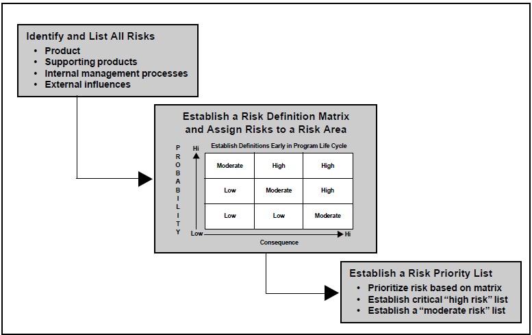
After identifying the risk items, the risk level should be established. One common method is through the use of a matrix such as shown in Figure 5-5. Each item is associated with a block in the matrix to establish relative risk among them.
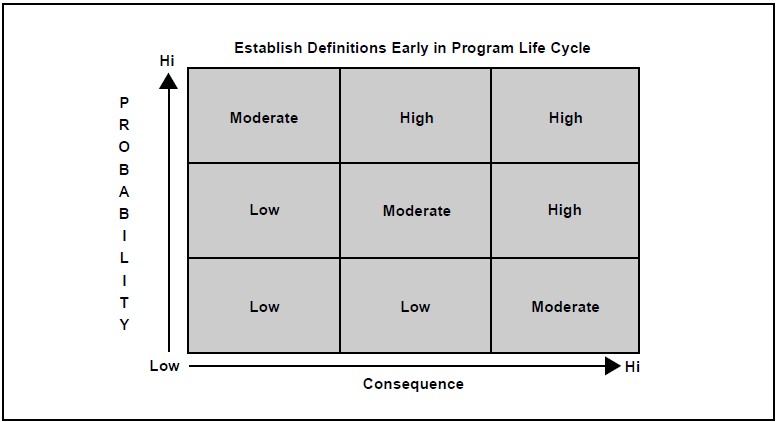
On such a graph risk increases on the diagonal and provides a method for assessing relative risk. Once the relative risk is known, a priority list can be established and risk analysis can begin.
Risk identification efforts can also include activities that help define the probability or consequences of a risk item, such as:
- Testing and analyzing uncertainty away,
- Testing to understand probability and consequences, and
- Activities that quantify risk where the qualitative nature of high, moderate, low estimates are insufficient for adequate understanding.
Risk Analysis Activities
Risk analysis activities continue the assessment process by refining the description of identified risk event through isolation of the cause of risk, determination of the full impact of risk, and the determination and choose of alternative courses of action. They are used to determine what risk should be tracked, what data is used to track risk, and what methods are used to handle the risk.
Risk analysis explores the options, opportunities, and alternatives associated with the risk. It ad-dresses the questions of how many legitimate ways the risk could be dealt with and the best way to do so. It examines sensitivity, and risk interrelation-ships by analyzing impacts and sensitivity of related risks and performance variation. It further analyzes the impact of potential and accomplished, external and internal changes.
Risk analysis activities that help define the scope and sensitivity of the risk item include finding answers to the following questions:
- If something changes, will risk change faster, slower, or at the same pace?
- If a given risk item occurs, what collateral effects happen?
- How does it affect other risks?
- How does it affect the overall situation?
- Development of a watch list (prioritized list of risk items that demand constant attention by management) and a set of metrics to determine if risks are steady, increasing, or decreasing.
- Development of a feedback system to track metrics and other risk management data.
- Development of quantified risk assessment.
Quantified risk assessment is a formal quantification of probabilities of occurrence and consequences using a top-down structured process following the WBS. For each element, risks are assessed through analysis, simulation and test to determine statistical probability and specific conditions caused by the occurrence of the consequence.
Cautions in Risk Assessments
Reliance solely on numerical values from simulations and analysis should be avoided. Do not lose sight of the actual source and consequences of the risks. Testing does not eliminate risk. It only provides data to assess and analyze risk. Most of all, beware of manipulating relative numbers, such as ‘risk index” or “risk scales,” even when based on expert opinion, as quantified data. They are important information, but they are largely subjetive and relative; they do not necessarily define risk accurately. Numbers such as these should always be the subject of a sensitivity analysis.
Risk Handling
Once the risks have been categorized and analyzed, the process of handling those risks is initiated. The prime purpose of risk handling activities is to mitigate risk. Methods for doing this are numerous, but all fall into four basic categories:
- Risk Avoidance,
- Risk Control,
- Risk Assumption, and
- Risk Transfer.
Avoidance
To avoid risk, remove requirements that represent uncertainty and high risk (probability or conse-quence.) Avoidance includes trading off risk for performance or other capability, and it is a key activity during requirements analysis. Avoidance requires understanding of priorities in requirements and constraints. Are they mission critical, mission enhancing, nice to have, or “bells and whistles?”
Control
Control is the deliberate use of the design process to lower the risk to acceptable levels. It requires the disciplined application of the systems engineering process and detailed knowledge of the technical area associated with the design. Control techniques are plentiful and include:
- Multiple concurrent design to provide more than one design path to a solution,
- Alternative low-risk design to minimize the risk of a design solution by using the lowest-risk design option,
- Incremental development, such as preplanned product improvement, to dissociate the design from high-risk components that can be developed separately,
- Technology maturation that allows high-risk components to be developed separately while the basic development uses a less risky and lower-performance temporary substitute,
- Test, analyze and fix that allows understanding to lead to lower risk design changes. (Test can be replaced by demonstration, inspection, early prototyping, reviews, metric tracking, experimentation, models and mock-ups, simulation, or any other input or set of inputs that gives a better understanding of the risk),
- Robust design that produces a design with substantial margin such that risk is reduced, and
- The open system approach that emphasizes use of generally accepted interface standards that provide proven solutions to component design problems.
Acceptance
Acceptance is the deliberate acceptance of the risk because it is low enough in probability and/or con-sequence to be reasonably assumed without impacting the development effort. Key techniques for handling accepted risk are budget and schedule reserves for unplanned activities and continuous assessment (to assure accepted risks are maintained at acceptance level). The basic objective of risk management in systems engineering is to reduce all risk to an acceptable level.
The strong budgetary strain and tight schedules on DoD programs tends to reduce the program manager’s and system engineer’s capability to pro-vide reserve. By identifying a risk as acceptable, the worst-case outcome is being declared accept-able. Accordingly, the level of risk considered acceptable should be chosen very carefully in a DoD acquisition program.
Transfer
Transfer can be used to reduce risk by moving the risk from one area of design to another where a design solution is less risky. Examples of this include:
- Assignment to hardware (versus software) or vice versa; and
- Use of functional partitioning to allocate performance based on risk factors.
Transfer is most associated with the act of assigning, delegating, or paying someone to assume the risk. To some extent transfer always occurs when contracting or tasking another activity. The con-tract or tasking document sets up agreements that can transfer risk from the government to contractor, program office to agency, and vice versa. Typical methods include insurance, warranties, and incentive clauses. Risk is never truly transferred. If the risk isn’t mitigated by the delegated activity it still affects your project or program.
Key areas to review before using transfer are:
- How well can the delegated activity handle the risk? Transfer is effective only to the level the risk taker can handle it.
- How well will the delegated activity solution integrate into your project or program? Transfer is effective only if the method is integrated with the overall effort. For example, is the warranty action coordinated with operators and maintainers?
- Was the method of tasking the delegated activity proper? Transfer is effective only if the transfer mechanism is valid. For example, can incentives be “gamed?”
- Who has the most control over the risk? If the project or program has no or little control over the risk item, then transfer should be considered to delegate the risk to those most likely to be able to control it.
Monitoring and Reporting
Risk monitoring is the continuous process of tracking and evaluating the risk management process by metric reporting, enterprise feedback on watch list items, and regular enterprise input on potential developing risks. (The metrics, watch lists, and feedback system are developed and maintained as an assessment activity.) The output of this process is then distributed throughout the enterprise, so that all those involved with the program are aware of the risks that affect their efforts and the system development as a whole.
Special Case – Integration as Risk
Integration of technologies in a complex system is a technology in itself! Technology integration during design may be a high-risk item. It is not normally assessed or analyzed as a separately identified risk item. If integration risks are not properly identified during development of the functional baseline, they will demonstrate themselves as serious problems in the development of the product baseline.
Special Case – Software Risk
Based on past history, software development is often a high-risk area. Among the causes of performance, schedule, and cost deficiencies have been:
- Imperfect understanding of operational requirements and its translation into source instructions,
- Risk tracking and handling,
- Insufficient comprehension of interface constraints, and
- Lack of sufficient qualified personnel.
Risk Awareness
All members of the enterprise developing the system must understand the need to pay attention to the existence and changing nature of risk.
Consequences that are unanticipated can seriously disrupt a development effort. The uneasy feeling that something is wrong, despite assurances that all is fine may be valid. These kinds of intuitions have allowed humanity to survive the slings and arrows of outrageous fortune throughout history. Though generally viewed as non-analytical, these apprehensions should not be ignored. Experience indicates those non-specific warnings have validity, and should be quantified as soon as possible.
6: Systems Engineering Planning
6.1 WHY ENGINEERING PLANS?
Systems engineering planning is an activity that has direct impact on acquisition planning decisions and establishes the feasible methods to achieve the acquisition objectives. Management uses it to:
- Assure that all technical activities are identified and managed,
- Communicate the technical approach to the broad development team,
- Document decisions and technical implementation, and
- Establish the criteria to judge how well the system development effort is meeting customer and management needs.
Systems engineering planning addresses the scope of the technical effort required to develop the system. The basic questions of “who will do what” and “when” are addressed. As a minimum, a technical plan describes what must be accomplished, how systems engineering will be done, how the effort will be scheduled, what resources are needed, and how the systems engineering effort will be monitored and controlled. The planning effort results in a management-oriented document covering the implementation of program requirements for system engineering, including technical management approaches for subsequent phases of the life cycle. In DoD it is an exercise done on a systems level by the government, and on a more detailed level by contractors.
Technical/Systems Engineering Planning
Technical planning may be documented in a separate engineering management plan or incorporated into a broad, integrated program management plan. This plan is first drafted at project or program inception during the early requirements analysis effort. Requirements analysis and technical planning are inherently linked, because requirements analysis establishes an understanding of what must be provided. This understanding is fundamental to the development of detailed plans.
To be of utility, systems engineering plans must be regularly updated. To support management decision making, major updates will usually occur at least just before major management milestone decisions. However, updates must be performed as necessary between management milestones to keep the plan sufficiently current to achieve its purpose of information, communication, and documentation.
6.2 ELEMENTS OF TECHNICAL PLANS
Technical plans should include sufficient information to document the purpose and method of the systems engineering effort. Plans should include the following:
- An introduction that states the purpose of the engineering effort and a description of the system being developed,
- A technical strategy description that ties the engineering effort to the higher-level management planning,
- A description of how the systems engineering process will be tailored and structured to complete the objectives stated in the strategy,
- An organization plan that describes the organizational structure that will achieve the engineering objectives, and
- A resource plan that identifies the estimated funding and schedule necessary to achieve the strategy.
Introduction
The introduction should include:
Scope: The scope of the plan should provide information concerning what part of the big pic-ture the plan covers. For example, if the plan were a DoD program office plan, it would emphasize control of the higher-level requirements, the system definition (functional baseline), and all activities necessary for system development. On the other hand, a contractor’s plan would emphasize control of lower-level requirements, preliminary and detail designs (allocated and product baselines), and activities required and limited by the contractual agreement.
Description: The description of the system should:
- Be limited to an executive summary describing those features that make the system unique,
- Include a general discussion of the system’s operational functions, and
- Answer the question “What is it and what will it do?”
Focus: A guiding focus for the effort should be provided to clarify the management vision for the development approach. For example, the focus may be lowest cost to obtain threshold requirements, superior performance within budget, superior standardization for reduced logistics, maximum use of the open systems approach to reduce cost, or the like. A focus statement should:
- Be a single objective to avoid confusion,
- Be stated simply to avoid misinterpretation, and
- Have high-level support.
Purpose: The purpose of the engineering effort should be described in general terms of the outputs, both end products and life-cycle enabling products that are required. The stated purpose should answer the question, “What does the engineering effort have to produce?”
Technical Strategy
The basic purpose of a technical strategy is to link the development process with the acquisition or contract management process. It should include:
- Development phasing and associated baselining,
- Key engineering milestones to support risk management and business management mile-stones,
- Associated parallel developments or product improvement considerations, and
- Other management generated constraints or high-visibility activities that could affect the engineering development.
Phasing and Milestones: The development phasing and baseline section should describe the approach to phasing the engineering effort, including tailoring of the basic process described in this course and a rationale for the tailoring. The key milestones should be in general keeping with the technical review process, but tailored as appropriate to support business management mile-stones and the project/program’s development phasing. Strategy considerations should also in-clude discussion of how design and verification will phase into production and fielding. This area should identify how production will be phased-in (including use of limited-rate initial production and long lead-time purchases), and that initial support considerations require significant coordination between the user and acquisition community.
Parallel Developments and Product Improvement: Parallel development programs necessary for the system to achieve its objectives should be identified and the relationship between the efforts explained. Any product improvement strategies should also be identified. Considerations such as evolutionary development and preplanned product improvement should be described in sufficient detail to show how they would phase into the overall effort.
Impacts on Strategy
All conditions or constraints that impact the strategy should be identified and the impact assessed. Key points to consider are:
- Critical technologies development,
- Cost As an Independent Variable (CAIV), and
- Any business management directed constraint or activity that will have a significant influence on the strategy.
Critical Technologies: Discussion of critical technology should include:
- Risk associated with critical technology development and its impact on the strategy,
- Relationship to baseline development, and
- Potential impact on the overall development effort.
Cost As an Independent Variable: Strategy considerations should include discussion of how CAIV will be implemented, and how it will impact the strategy. It should discuss how unit cost, development cost, life cycle cost, total ownership cost, and their interrelationships apply to the system development. This area should focus on how these costs will be balanced, how they will be con-trolled, and what impact they have on the strategy and design approach.
Management Issues: Management issues that pose special concerns for the development strategy could cover a wide range of possible issues. In general, management issues identified as engineering strategy issues are those that impact the ability to support the management strategy. Examples would include:
- Need to combine developmental phases to accommodate management driven schedule or resource limitations,
- Risk associated with a tight schedule or limited budget,
- Contractual approach that increases technical risk, and
- Others of a similar nature.
Management-dictated technical activities—such as use of M&S, open systems, IPPD, and others—should not be included as a strategy issue unless they impact the overall systems engineering strategy to meet management expectations. The strategy discussion should lay out the plan, how it dovetails with the management strategy, and how management directives impact it.
Systems Engineering Processes
This area of the planning should focus on how the system engineering processes will be designed to support the strategy. It should include:
- Specific methods and techniques used to perform the steps and loops of the systems engineering process,
- Specific system analysis and control tools and how they will be used to support step and loop activities, and
- Special design considerations that must be integrated into the engineering effort.
Steps and Loops: The discussion of how the systems engineering process will be done should show the specific procedures and products that will ensure:
- Requirements are understood prior to the flow-down and allocation of requirements,
- Functional descriptions are established before designs are formulated,
- Designs are formulated that are traceable to requirements,
- Methods exist to reconsider previous steps, and
- Verification processes are in place to ensure that design solutions meet needs and requirements.
This planning area should address each step and loop for each development phase, include identification of the step-specific tools (Functional Flow Block Diagrams, Timeline Analysis, etc.) that will be used, and establish the verification approach. The verification discussion should identify all verification activities, the relationship to formal developmental T&E activities, and independent testing activities (such as operational testing).
Norms of the particular technical area and the engineering processes of the command, agency, or company doing the tasks will greatly influence this area of planning. However, whatever procedures, techniques, and analysis products or models used, they should be compatible with the basic principles of systems engineering management as described earlier in this course.
An example of the type of issue this area would address is the requirements analysis during the system definition phase. Requirements analysis is more critical and a more central focus during system definition than in later phases. The establishment of the correct set of customer requirements at the beginning of the development effort is essential to proper development. Accordingly, the system definition phase requirements analysis demands tight control and an early review to verify the requirements are established well enough to begin the design effort. This process of control and verification necessary for the system definition phase should be specifically described as part of the overall requirements analysis process and procedures.
Analysis and Control: Planning should identify those analysis tools that will be used to evaluate alternative approaches, analyze or assess effective-ness, and provide a rigorous quantitative basis for selecting performance, functional, and design requirements. These processes can include trade studies, market surveys, M&S, effectiveness analyses, design analyses, QFD, design of experiments, and others.
Planning must identify the method by which control and feedback will be established and maintained. The key to control is performance-based measurement guided by an event-based schedule. Entrance and exit criteria for the event-driven milestones should be established sufficient to demonstrate proper development progress has been completed. Event-based schedules and exit criteria are further discussed later in this chapter. Methods to maintain feedback and control are developed to monitor progress toward meeting the exit criteria. Common methods were discussed earlier in this course in the chapters on metrics, risk management, configuration management, and technical reviews.
Design Considerations: In every system development there are usually technical activities that require special attention. These may come from management concerns, legal or regulatory directives, social issues, or organizational initiatives. For example, a DoD program office will have to con-form to DoDD 5000.2-R, which lists several technical activities that must be incorporated into the development effort. DoD plans should specifically address each issue presented in the Program Design section of DoD 5000.2-R.
In the case of a contractor there may be issues de-lineated in the contract, promised in the proposal, or established by management that the technical effort must address. The system engineering planning must describe how each of these issues will be integrated into the development effort.
Organization
Systems engineering management planning should identify the basic structure that will develop the system. Organizational planning should address how the integration of the different technical disciplines, primary function managers, and other stakeholders will be achieved to develop the system. This planning area should describe how multi-disciplinary teaming would be implemented, that is, how the teams will be organized, tasked, and trained. A systems-level team should be established early to support this effort. Roles, authority, and basic responsibilities of the system-level design team should be specifically described. Establishing the design organization should be one of the initial tasks of the system-level design team. Their basic approach to organizing the effort should be described in the plan. Further information on organizing is contained in a later chapter.
Resources
The plan should identify the budget for the technical development. The funds required should be matrixed against a calendar schedule based on the event-based schedule and the strategy. This should establish the basic development timeline with an associated high-level estimated spending profile. Shortfalls in funding or schedule should be ad-dressed and resolved by increasing funds, extending schedule, or reducing requirements prior to the plan preparation. Remember that future analysis of development progress by management will tend to be based on this budget “promised” at plan inception.
6.3 INTEGRATION OF PLANS – PROGRAM PLAN INTERFACES
Systems engineering management planning must be coordinated with interfacing activities such as these:
- Acquisition Strategy assures that technical plans take into account decisions reflected in the Acquisition Strategy. Conflicts must be identified early and resolved.
- Financial plan assures resources match the needs in the tech plan. Conflicts should be identified early and resolved.
- Test and Evaluation Master Plan (TEMP) assures it complements the verification approach. It should provide an integrated approach to verify that the design configuration will meet customer requirements. This approach should be compatible with the verification approach delineated in the systems engineering plan.
- Configuration management plan assures that the development process will maintain the system baselines and control changes to them.
- Design plans (e.g., electrical, mechanical, structural, etc.) coordinates identification of IPT team composition.
- Integrated logistics support planning and sup-port analysis coordinates total system support.
- Production/Manufacturing plan to coordinate activities concerning design producibility, and follow-on production,
- Quality management planning assures that quality engineering activities and quality management functions are included in system engineering planning,
- Risk management planning establishes and coordinates technical risk management to support total program risk management.
- Interoperability planning assures interoperability suitability issues are coordinated with system engineering planning. (Where interoperability is an especially critical requirement such as, communication or information systems, it should be addressed as a separate issue with separate integrated teams, monitoring, and controls).
- Others such as M&S plan, software development plan, human integration plan, environment, safety and health planning, also interface.
Things to Watch
A well developed technical management plan will include:
- The expected benefit to the user,
- How a total systems development will be achieved using a systems engineering approach,
- How the technical plan complements and sup-ports the acquisition or management business plan,
- How incremental reviews will assure that the development stays on track,
- How costs will be reduced and controlled,
- What technical activities are required and who will perform them,
- How the technical activities relate to work accomplishment and calendar dates,
- How system configuration and risk will be controlled,
- How system integration will be achieved,
- How the concerns of the eight primary life cycle functions will be satisfied,
- How regulatory and contractual requirements will be achieved, and
- The feasibility of the plan, i.e., is the plan practical and executable from a technical, schedule, and cost perspective.
7: Product Improvement Strategies
7.1 INTRODUCTION
Complex systems do not usually have stagnant configurations. A need for a change during a system’s life cycle can come from many sources and effect the configuration in infinite ways. The problem with these changes is that, in most cases it is difficult, if not impossible, to predict the nature and timing of these changes at the beginning of system development. Accordingly, strategies or design approaches have been developed to reduce the risk associated with predicted and unknown changes.
Well thought-out improvement strategies can help control difficult engineering problems related to:
- Requirements that are not completely under-stood at program start,
- Technology development that will take longer than the majority of the system development,
- Customer needs (such as the need to combat a new military threat) that have increased, been upgraded, are different, or are in flux,
- Requirements change due to modified policy, operational philosophy, logistics support philosophy, or other planning or practices from the eight primary life cycle function groups,
- Technology availability that allows the system to perform better and/or less expensively,
- Potential reliability and maintainability up-grades that make it less expensive to use, maintain, or support, including development of new supply support sources,
- Safety issues requiring replacement of unsafe components, and
- Service life extension programs that refurbish and upgrade systems to increase their service life.
In DoD, the 21st century challenge will be improving existing products and designing new ones that can be easily improved. With the average service life of a weapons system in the area of 40 or more years, it is necessary that systems be developed with an appreciation for future requirements, fore-seen and unforeseen. These future requirements will present themselves as needed upgrades to safety, performance, supportability, interface compatibility, or interoperability; changes to reduce cost of ownership; or major rebuild. Providing these needed improvements or corrections form the majority of the systems engineer’s post-production activities.
7.2 PRODUCT IMPROVEMENT STRATEGIES
As shown by Figure 7-1, these strategies vary based on where in the life cycle they are applied. The strategies or design approaches that reflect these improvement needs can be categorized as planned improvements, changes in design or production, and deployed system upgrades.
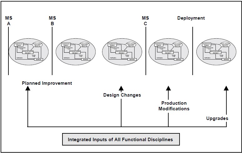
Planned Improvements
Planned improvements strategies include evolutionary acquisition, preplanned product development, and open systems. These strategies are not exclusive and can be combined synergistically in a program development.
Evolutionary Acquisition: Evolutionary acquisition is the preferred approach to systems acquisition in DoD. In an environment where technology is a fast moving target and the key to military superiority is a technically superior force, the requirement is to transition useful capability from development to the user as quickly as possible, while laying the foundation for further changes to occur at later dates. Evolutionary acquisition is an approach that defines requirements for a core capability, with the understanding that the core is to be augmented and built upon (evolved) until the system meets the full spectrum of user requirements. The core capability is defined as a function of user need, technology maturity, threat, and budget. The core is then expanded as need evolves and the other factors mentioned permit.
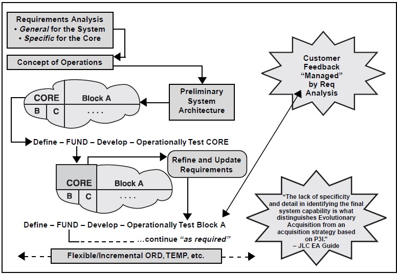
A key to achieving evolutionary acquisition is the use of time-phased requirements and continuous communication with the eventual user, so that requirements are staged to be satisfied incrementally, rather than in the traditional single grand design approach. Planning for evolutionary acquisition also demands that engineering designs be based on open system, modular design concepts that per-mit additional increments to be added over time without having to completely re-design and re-develop those portions of the system already fielded. Open designs will facilitate access to recent changes in technologies and will also assist in con-trolling costs by taking advantage of commercial competition in the marketplace. This concept is not new; it has been employed for years in the C4ISR community, where system are often in evolution over the entire span of their lifecycles.
Preplanned Product Improvement (P3I): Often referred to as P3I, preplanned product improvement is an appropriate strategy when requirements are known and firm, but where constraints (typically either technology or budget) make some portion of the system unachievable within the schedule required. If it is concluded that a militarily useful capability can be fielded as an interim solution while the portion yet to be proceeds through development, then P3I is appropriate. The approach generally is to handle the improvement as a separate, parallel development; initially test and deliver the system without the improvement; and prove and provide the enhanced capability as it becomes available. The key to a successful P3I is the establishment of well-defined interface requirements for the system and the improvement. Use of a P3I will tend to increase initial cost, configuration management activity, and technical complexity. Figure 7-3 shows some of the considerations in deciding when it is appropriate.
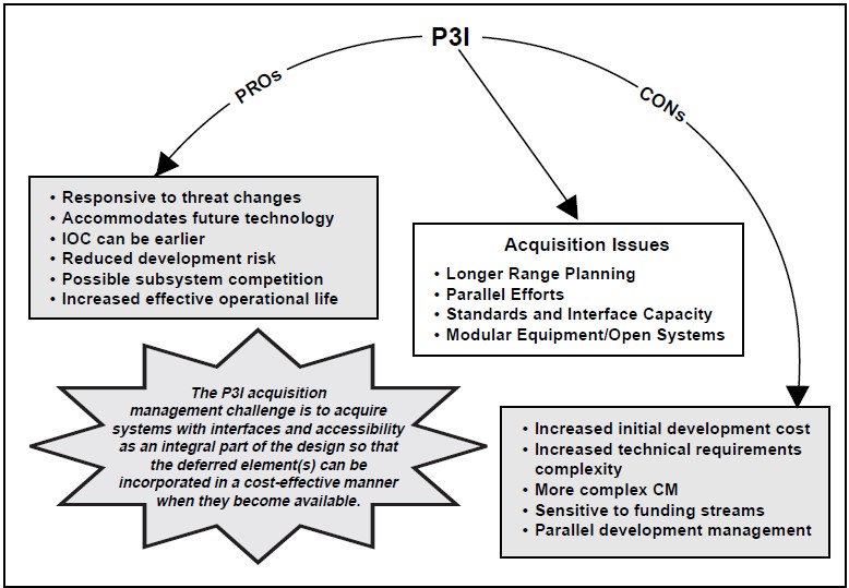
Open Systems Approach: The open system design approach uses interface management to build flexible design interfaces that accommodate use of competitive commercial products and provide enhanced capacity for future change. It can be used to prepare for future needs when technology is yet not available, whether the operational need is known or unknown. The open systems focus is to design the system such that it is easy to modify using standard interfaces, modularity, recognized interface standards, standard components with recognized common interfaces, commercial and non-developmental items, and compartmentalized design. Open system approaches to design are further discussed at the end of this chapter.
Changes in Design or Production
Engineering Change Proposals (ECPs): Changes that are to be implemented during the development and production of a given system are typically initiated through the use of ECPs. If the proposed change is approved (usually by a configuration control board) the changes to the documentation that describes the system are handled by formal configuration management, since, by definition, ECPs, when approved, change an approved base-line. ECPs govern the scope and details of these changes. ECPs may address a variety of needs, including correction of deficiencies, cost reduction, and safety. Furthermore, ECPs may been as-signed differing levels of priority from routine to emergency. MIL-HDBK-61, Configuration Management Guidance, offers an excellent source of advice on issues related to configuration changes.
Block Change before Deployment: Block changes represent an attempt to improve configuration management by having a number of changes grouped and applied such that they will apply consistently to groups (or blocks) of production items. This improves the management and configuration control of similar items substantially in comparison to change that is implemented item by item and single change order by single change order. When block changes occur, the life cycle impact should be carefully addressed. Significant differences in block configurations can lead to different manuals, supply documentation, training, and restrictions as to locations or activities where the system can be assigned.
Deployed Systems Upgrades
Major Rebuild: A major rebuild results from the need for a system that satisfies requirements significantly different or increased from the existing system, or a need to extend the life of a system that is reaching the end of its usable life. In both cases the system will have upgraded requirements and should be treated as basically a new system development. A new development process should be started to establish and control configuration baselines for the rebuilt system based on the updated requirements.
Major rebuilds include remanufacturing, service-life extension programs, and system developments where significant parts of a previous system will be reused. Though rebuilding existing systems can dramatically reduce the cost of a new system in some cases, the economies of rebuild can be deceiving, and the choice of whether to pursue a rebuild should be done after careful use of trade studies. The key to engineering such systems is to remember that they are new systems and require the full developmental considerations of baselining, the systems engineering process, and life cycle integration.
Post-Production Improvement: In general, product improvements become necessary to improve the system or to maintain the system as its components reach obsolescence. These projects generally result in a capability improvement, but for all practical purposes the system still the serves the same basic need. These improvements are usually characterized by an upgrade to a component or sub-system as opposed to a total system upgrade.
Block Upgrades: Post-production block upgrades are improvements to a specific group of the system population that provides a consistent configuration within that group. Block upgrades in post-production serve the same general purpose of controlling individual system configurations as production block upgrades, and they require the same level of life-cycle integration.
Modifying an Existing System
Upgrading an existing system is a matter of following the system engineering process, with an emphasis on configuration and interface management. The following activities should be included when upgrading a system:
- Benchmark the modified requirements both for the upgrade and the system as a whole,
- Perform functional analysis and allocation on the modified requirements,
- Assess the actual capability of the pre-upgrade system,
- Identify cost and risk factors and monitor them,
- Develop and evaluate modified system alternatives,
- Prototype the chosen improvement alternative, and
- Verify the improvement.
Product improvement requires special attention to configuration and interface management. It is not uncommon that the existing system’s con-figuration will not be consistent with the existing configuration data. Form, fit, and especially function interfaces often represent design constraints that are not always readily apparent at the outset of a system upgrade. Upgrade planning should ensure that the revised components will be compatible at the interfaces. Where interfaces are impacted, broad coordination and agreement is normally required.
Traps in Upgrading Deployed Systems
When upgrading a deployed system pay attention to the following significant traps:
Scheduling to minimize operational impacts: The user’s operational commitments will dictate the availability of the system for modification. If the schedule conflicts with an existing or emerging operational need, the system will probably not become available for modification at the time agreed to. Planning and contractual arrangements must be flexible enough to accept unforeseen schedule changes to accommodate user’s unanticipated needs.
Configuration and interface management: Con-figuration management must address three configurations: the actual existing configuration, the modification configuration, and the final system con-figuration. The key to successful modification is the level of understanding and control associated with the interfaces.
Logistics compatibility problems: Modification will change the configuration, which in most cases will change the supply support and maintenance considerations. Coordination with the logistics community is essential to the long-term operational success of the modification.
Minimal resources available: Modifications tend to be viewed as simple changes. As this chapter has pointed out, they are not; and they should be carefully planned. That planning should include an estimate of needed resources. If the resources are not available, either the project should be abandoned, or a plan formulated to mitigate and control the risk of an initial, minimal budget com-bined with a plan for obtaining additional resources.
Limited competitors: Older systems may have only a few suppliers that have a corporate knowledge of the particular system functions and design. This is especially problematic if the original system components were commercial or NDIs that the de-signer does not have product baseline data for. In cases such as these, there is a learning process that must take place before the designer or vendor can adequately support the modification effort. De-pending on the specific system, this could be a major effort. This issue should be considered very early in the modification process because it has serious cost implications.
Government funding rules: As Figure 7-4 shows the use of government funding to perform system upgrades has restrictions. The purpose of the up-grade must be clear and justified in the planning efforts.
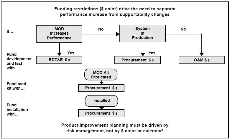
7.3 ROLES AND RESPONSIBILITIES
Modification management is normally a joint government and contractor responsibility. Though any specific system upgrade will have relationships established by the conditions surrounding the particular program, government responsibilities would usually include:
- Providing a clear statement of system requirements,
- Planning related to government functions,
- Managing external interfaces,
- Managing the functional baseline configuration, and
- Verifying that requirements are satisfied.
Contractor responsibilities are established by the contract, but would normally include:
- Technical planning related to execution,
- Defining the new performance envelope,
- Designing and developing modifications, and
- Providing evidence that changes made have modified the system as required.
System Engineering Role
The systems engineering role in product improvement includes:
- Planning for system change,
- Applying the systems engineering process,
- Managing interface changes,
- Identifying and using interface standards which facilitate continuing change,
- Ensuring life cycle management is implemented,
- Monitoring the need for system modifications, and
- Ensuring operations, support activities, and early field results are considered in planning.
8: Organizing and Integrating System Development
8.1 INTEGRATED DEVELOPMENT
DoD has, for years, required that system designs be integrated to balance the conflicting pressure of competing requirements such as performance, cost, supportability, producibility, and testability. The use of multi-disciplinary teams is the approach that both DoD and industry increasing have taken to achieve integrated designs. Teams have been found to facilitate meeting cost, performance, and other objectives from product concept through disposal.
The use of multi-disciplinary teams in design is known as Integrated Product and Process Development, simultaneous engineering, concurrent engineering, Integrated Product Development, Design-Build, and other proprietary and non-proprietary names expressing the same concept. (The DoD use of the term Integrated Product and Process Development (IPPD) is a wider concept that includes the systems engineering effort as an element. The DoD policy is explained later in this chapter.) Whatever name is used, the fundamental idea involves multi-functional, integrated teams (preferably co-located), that jointly derive requirements and schedules that place equal emphasis on product and process development. The integration requires:
- Inclusion of the eight primary functions in the team(s) involved in the design process,
- Technical process specialties such as quality, risk management, safety, etc., and
- Business processes (usually in an advisory capacity) such as, finance, legal, contracts, and other non-technical support.
Benefits
The expected benefits from team-based integration include:
- Reduced rework in design, manufacturing, planning, tooling, etc.,
- Improved first time quality and reduction of product variability,
- Reduced cost and cycle time,
- Reduced risk,
- Improved operation and support, and
- General improvement in customer satisfaction and product quality throughout its life cycle.
Characteristics
The key attributes that characterize a well integrated effort include:
- Customer focus,
- Concurrent development of products and processes,
- Early and continuous life cycle planning,
- Maximum flexibility for optimization,
- Robust design and improved process capability,
- Event-driven scheduling,
- Multi-disciplinary teamwork,
- Empowerment,
- Seamless management tools, and
- Proactive identification and management of risk.
Organizing for System Development
Most DoD program offices are part of a Program Executive Office (PEO) organization that is usually supported by a functional organization, such as a systems command. Contractors and other government activities provide additional necessary support. Establishing a system development organization requires a network of teams that draw from all these organizations. This network, sometimes referred to as the enterprise, represents the interests of all the stakeholders and provides vertical and horizontal communications.
These integrated teams are structured using the WBS and designed to provide the maximum vertical and horizontal communication during the development process. Figure 8-1 shows how team structuring is usually done. At the system level there is usually a management team and a design team. The management team would normally consist of the government and contractor program managers, the deputy program manager(s), possibly the contractor Chief Executive Officer, the contracting officer, major advisors picked by the program manager, the system design team leader, and other key members of the system design team. The design team usually consists of the first-level subsystem and life-cycle integrated team leaders.
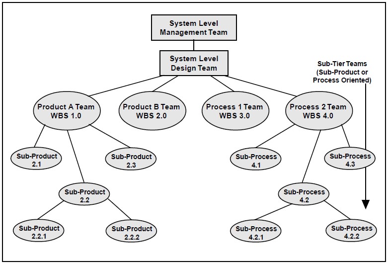
The next level of teams is illustrated on Figure 8-1 as either product or process teams. These teams are responsible for designing system segments (product teams) or designing the supporting or enabling products (process teams). At this level the process teams are coordinating the system level process development. For example, the support team will integrate the supportability analysis from the parts being generated in lower-level design and support process teams. Teams below this level continue the process at a lower level of decomposition. Teams are formed only to the lowest level necessary to control the integration. DoD team structures rarely extend lower than levels three or four on the WBS, while contractor teams may ex-tend to lower levels, depending on the complexities of the project and the approach favored by management.
The team structure shown by Figure 8-1 is a hierarchy that allows continuous vertical communication. This is achieved primarily by having the team leaders, and, if appropriate, other key members of a team, be team members of the next highest team. In this manner the decisions of the higher team is immediately distributed and explained to the next team level, and the decisions of the lower teams are presented to the higher team on a regular basis. Through this method decisions of lower-level teams follow the decision making of higher teams, and the higher-level teams’ decisions incorporate the concerns of lower-level teams.
The normal method to obtain horizontal communication is shown in Figure 8-2. At least one team member from the Product A Team is also a member of the Integration and Test Team. This member would have a good general knowledge of both testing and Product A. The member’s job would be to assist the two teams in designing their end or enabling products, and in making each understand how their decisions would impact the other team. Similarly, the member that sits on both Product A and B teams would have to understand the both technology and the interface issues associated with both items.
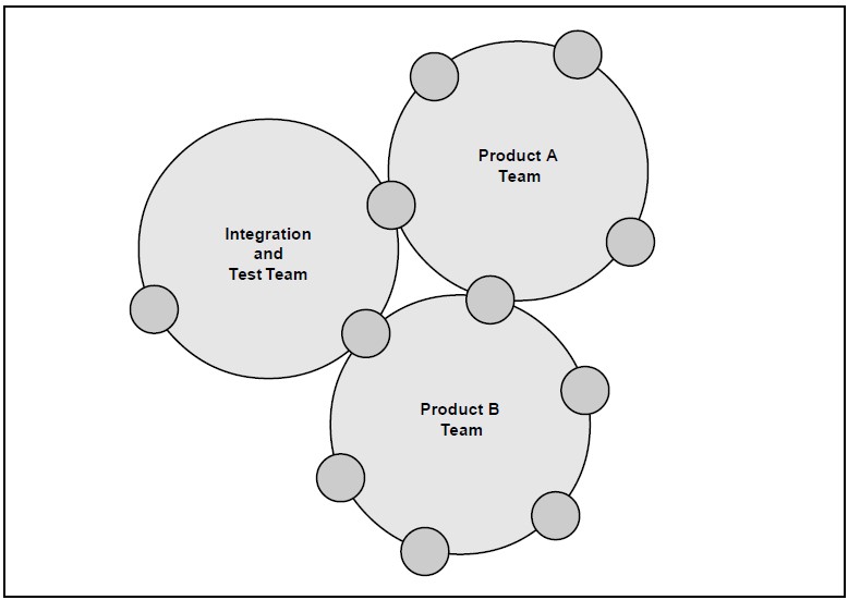
The above is an idealized case. Each type of system, each type of contractor organization, and each level of available resources requires a tailoring of this structure. With each phase the focus and the tasks change and so should the structure. As phases are transited, the enterprise structure and team membership should be re-evaluated and updated.
8.2 INTEGRATED TEAMS
Integrated teams are composed of representatives from all appropriate primary functional disciplines working together with a team leader to:
- Design successful and balanced products,
- Develop the configuration for successful life-cycle control,
- Identify and resolve issues, and
- Make sound and timely decisions.
The teams follow the disciplined approach of the systems engineering process starting with requirements analysis through to the development of con-figuration baselines as explained earlier in this course. The system-level design team should be responsible for systems engineering management planning and execution. The system-level management team, the highest level program IPT, is responsible for acquisition planning, resource allocation, and management. Lower-level teams are responsible for planning and executing their own processes.
Team Organization
Good teams do not just happen; they are the result of calculated management decisions and actions. Concurrent with development of the enterprise organization discussed above, each team must also be developed. Basically the following are key considerations in planning for a team within an enterprise network:
- The team must have appropriate representation from the primary functions, technical special-ties, and business support,
- There must be links to establish vertical and horizontal communication in the enterprise,
- You should limit over-uses of cross member-ship. Limit membership on three or four teams as a rough rule of thumb for the working level, and
- Ensure appropriate representation of government, contractor, and vendors to assure integration across key organizations.
Team Development
When teams are formed they go through a series of phases before a synergistic self-actuating team is evolved. These phases are commonly referred to as forming, storming, norming and performing. The timing and intensity of each phase will depend on the team size, membership personality, effectiveness of the team building methods employed, and team leadership. The team leaders and an enterprise-level facilitator provide leadership during the team development.
Forming is the phase where the members are introduced to their responsibilities and other members. During this period members will tend to need a structured situation with clarity of purpose and process. If members are directed during this initial phase, their uncertainty and therefore apprehension is reduced. Facilitators controlling the team building should give the members rules and tasks, but gradually reduce the level of direction as the team members begin to relate to each other. As members become more familiar with other members, the rules, and tasks, they become more comfortable in their environment and begin to interact at a higher level.
This starts the storming phase. Storming is the conflict brought about by interaction relating to the individuals’ manner of dealing with the team tasks and personalities. Its outcome is members who understand the way they have to act with other members to accomplish team objectives. The dynamics of storming can be very complex and in-tense, making it the critical phase. Some teams will go through it quickly without a visible ripple, others will be loud and hot, and some will never emerge from this phase. The team building facilitators must be alert to dysfunctional activity.
Members may need to be removed or teams reorganized. Facilitators during this period must act as coaches, directing but in a personal collaborative way. They should also be alert for members that are avoiding storming, because the team will not mature if there are members who are not personally committed to participate in it.
Once the team has learned to interact effectively it begins to shape its own processes and become more effective in joint tasks. It is not unusual to see some reoccurrence of storming, but if the storming phase was properly transitioned these incidences should be minor and easily passed. In this phase, norming, the team building facilitators become a facilitator to the team—not directing, but asking penetrating questions to focus the members. They also monitor the teams and correct emerging problems.
As the team continues to work together on their focused tasks, their performance improves until they reach a level of self-actuation and quality decision making. This phase, performing, can take a while to reach, 18 months to two years for a system-level design team would not be uncommon. During the performing stage, the team building facilitator monitors the teams and corrects emerging problems.
At the start of a project or program effort, team building is commonly done on an enterprise basis with all teams brought together in a team-building exercise. There are two general approaches to the exercise:
- A team-learning process where individuals are given short but focused tasks that emphasize group decision, trust, and the advantages of diversity.
- A group work-related task that is important but achievable, such as a group determination of the enterprise processes, including identifying and removing non-value added traditional processes.
Usually these exercises allow the enterprise to pass through most of the storming phase if done correctly. Three weeks to a month is reasonable for this process, if the members are in the same location. Proximity does matter and the team build-ing and later team performance are typically better if the teams are co-located.
8.3 TEAM MAINTENANCE
Teams can be extremely effective, but they can be fragile. The maintenance of the team structure is related to empowerment, team membership issues, and leadership.
Empowerment
The term empowerment relates to how responsibilities and authority is distributed throughout the enterprise. Maintenance of empowerment is important to promote member ownership of the development process. If members do not have personal ownership of the process, the effective-ness of the team approach is reduced or even neutralized. The quickest way to destroy participant ownership is to direct, or even worse, over-turn solutions that are properly the responsibility of the team. The team begins to see that the responsibility for decisions is at a higher level rather than at their level, and their responsibility is to follow orders, not solve problems.
Empowerment requires:
- The flow of authority through the hierarchy of teams, not through personal direction (irrespective of organizational position). Teams should have clear tasking and boundaries established by the higher-level teams.
- Responsibility for decision making to be appropriate for the level of team activity. This requires management and higher-level teams to be specific, clear, complete, and comprehensive in establishing focus and tasking, and in specifying what decisions must be coordinated with higher levels. They should then avoid imposing or overturning decisions more properly in the realm of a lower level.
- Teams at each level be given a clear understanding of their duties and constraints. Within the bounds of those constraints and assigned duties members should have autonomy. Higher-level teams and management either accept their decisions, or renegotiate the understanding of the task.
Membership Issues
Another maintenance item of import is team member turnover. Rotation of members is a fact of life, and a necessary process to avoid teams becoming too closed. However, if the team has too fast a turn-over, or new members are not fully assimilated, the team performance level will decline and possibly revert to storming. The induction process should be a team responsibility that includes the immediate use of the new team member in a jointly performed, short term, easily achievable, but important task.
Teams are responsible for their own performance, and therefore should have significant, say over the choice of new members. In addition teams should have the power to remove a member; however, this should be preceded by identification of the problem and active intervention by the facilitator. Removal should be a last resort.
Awards for performance should, where possible, be given to the team rather than individuals (or equally to all individuals on the team). This achieves several things: it establishes a team focus, shows recognition of the team as a cohesive force, recognizes that the quality of individual effort is at least in part due to team influence, reinforces the membership’s dedication to team objectives, and avoids team member segregation due to uneven awards. Some variation on this theme is appropriate where different members belong to different organizations, and a common award system does not exist. The system-level management team should address this issue, and where possible assure equitable awards are given team members. A very real constraint on cash awards in DoD rises in the case of teams that include both civilian and military members. Military members cannot be given cash awards, while civilians can. Consequently, managers must actively seek ways to reward all team members appropriately, leaving no group out at the expense of others.
Leadership
Leadership is provided primarily by the organizational authority responsible for the program, the enterprise facilitator, and the team leaders. In a DoD program, the organizational leaders are usually the program manager and contractor senior manager. These leaders set the tone of the enterprise adherence to empowerment, the focus of the technical effort, and the team leadership of the system management team. These leaders are responsible to see that the team environment is maintained. They should coordinate their action closely with the facilitator.
Facilitators
Enterprises that have at least one facilitator find that team and enterprise performance is easier to maintain. The facilitator guides the enterprise through the team building process, monitors the team network through metrics and other feed-back, and makes necessary corrections through facilitation. The facilitator position can be:
- A separate position in the contractor organization,
- Part of the responsibilities of the government systems engineer or contractor project manager, or
- Any responsible position in the first level below the above that is related to risk management.
Obviously the most effective position would be one that allows the facilitator to concentrate on the teams’ performance. Enterprise level facilitators should have advanced facilitator training and (recommended) at least a year of mentored experience. Facilitators should also have significant broad experience in the technical area related to the development.
Team Leaders
The team leaders are essential for providing and guiding the team focus, providing vertical communication to the next level, and monitoring the team’s performance. Team leaders must have a clear picture of what constitutes good performance for their team. They are not supervisors, though in some organizations they may have supervisory administrative duties. The leader’s primary purpose is to assure that the environment is present that allows the team to perform at its optimum level—not to direct or supervise.
The team leader’s role includes several difficult responsibilities:
- Taking on the role of coach as the team forms,
- Facilitating as the team becomes self-sustaining,
- Sometimes serving as director (only when a team has failed, needs refocus or correction, and is done with the facilitator),
- Providing education and training for members,
- Facilitating team learning,
- Representing the team to upper management and the next higher-level team, and
- Facilitating team disputes.
Team leaders should be trained in basic facilitator principles. This training can be done in about a week, and there are numerous training facilities or companies that can offer it.
8.4 TEAM PROCESSES
Teams develop their processes from the principles of system engineering management as presented earlier in the course. The output of the teams is the design documentation associated with products identified on the system architecture, including both end product components and enabling products.
Teams use several tools to enhance their productivity and improve communication among enterprise members. Some examples are:
- Constructive modeling (CAD/CAE/CAM/CASE) to enhance design understanding and control,
- Trade-off studies and prioritization,
- Event-driven schedules,
- Prototyping,
- Metrics, and most of all
- Integrated membership that represents the life cycle stakeholders.
Integrated Team Rules
The following is a set of general rules that should guide the activities and priorities of teams in a system design environment:
- Design results must be communicated clearly, effectively, and timely.
- Design results must be compatible with initially defined requirements.
- Continuous “up-the-line” communication must be institutionalized.
- Each member needs to be familiar with all system requirements.
- Everyone involved in the team must work from the same database.
- Only one member of the team has the authority to make changes to one set of master documentation.
- All members have the same level of authority (one person, one vote).
- Team participation is consistent, success-oriented, and proactive.
- Team discussions are open with no secrets.
- Team member disagreements must be reasoned disagreement (alternative plan of action versus unyielding opposition).
- Trade studies and other analysis techniques are used to resolve issues.
- Issues are raised and resolved early.
- Complaints about the team are not voiced outside the team. Conflicts must be resolved internally.
Guidelines for Meeting Management
Even if a team is co-located as a work unit, regular meetings will be necessary. These meetings and their proper running become even more important if the team is not co-located and the meeting is the primary means of one-on-one contact. A well-run technical meeting should incorporate the following considerations:
- Meetings should be held only for a specific purpose and a projected duration should be targeted.
- Advance notice of meetings should normally be at least two weeks to allow preparation and communication between members.
- Agendas, including time allocations for topics and supportive material should be distributed no less than three business days before the team meeting. The objective of the meeting should be clearly defined.
- Stick to the agenda during the meeting. Then cover new business. Then review action items.
- Meeting summaries should record attendance, document any decision or agreements reached, document action items and associated due-dates, provide a draft agenda for the next meeting, and frame issues for higher-level resolution.
- Draft meeting summaries should be provided to members within one working day of the meeting. A final summary should be issued within two working days after the draft comments deadline.
8.5 BARRIERS TO INTEGRATION
There are numerous barriers to building and maintaining a well functioning team organization, and they are difficult to overcome. Any one of these barriers can negate the effectiveness of an integrated development approach. Common barriers include:
- Lack of top management support,
- Team members not empowered,
- Lack of access to a common database,
- Lack of commitment to a cultural change,
- Functional organization not fully integrated into a team process,
- Lack of planning for team effort,
- Staffing requirements conflict with teams,
- Team members not collocated,
- Insufficient team education and training,
- Lessons learned and successful practices not shared across teams,
- Inequality of team members,
- Lack of commitment based on perceived uncertainty,
- Inadequate resources, and
- Lack of required expertise on either the part of the contractor or government.
Breaking Barriers
Common methods to combat barriers include:
- Education and training, and then more education and training: it breaks down the uncertainty of change, and provides a vision and method for success.
- Use a facilitator not only to build and maintain teams, but also to observe and advise management.
- Obtain management support up front. Management must show leadership by managing the teams’ environment rather than trying to manage people.
- Use a common database open to all enterprise members.
- Establish a network of teams that integrates the design and provides horizontal and vertical communication.
- Establish a network that does not over-tax avail-able resources. Where a competence is not avail-able in the associated organizations, hire it through a support contractor.
- Where co-location is not possible have regular working sessions of several days duration. Tele-communications, video conferencing, and other technology based techniques can also go far to alleviate the problems of non-collocation.
9: Contractual Considerations
9.1 INTRODUCTION
This chapter describes how the systems engineer supports the development and maintenance of the agreement between the project office and the con-tractor that will perform or manage the detail work to achieve the program objectives. This agreement has to satisfy several stakeholders and requires coordination between responsible technical, managerial, financial, contractual, and legal personnel. It requires a document that conforms to the Federal Acquisition Regulations (and supplements), program PPBS documentation, and the System Architecture. As shown by Figure 9-1, it also has to result in a viable cooperative environment that allows necessary integrated teaming to take place.
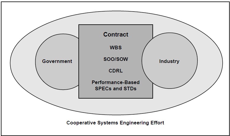
The role of technical managers or systems engineers is crucial to satisfying these diverse concerns. Their primary responsibilities include:
- Supporting or initiating the planning effort. The technical risk drives the schedule and cost risks which in turn should drive the type of contractual approach chosen,
- Prepares or supports the preparation of the source selection plan and solicitation clauses concerning proposal requirements and selection criteria,
- Prepares task statements,
- Prepares the Contract Data Requirements List (CDRL),
- Supports negotiation and participates in source selection evaluations,
- Forms Integrated Teams and coordinates the government side of combined government and industry integrated teams,
- Monitors the contractor’s progress, and
- Coordinates government action in support of the contracting officer.
This chapter reflects the DoD approach to contracting for system development. It assumes that there is a government program or project office that is tasking a prime contractor in a competitive environment. However, in DoD there is variation to this theme. Some project activities are tasked directly to a government agency or facility, or are contracted sole source. The processes described in this chapter should be tailored as appropriate for these situations.
9.2 SOLICITATION DEVELOPMENT
As shown by Figure 9-2, the DoD contracting process begins with planning efforts. Planning includes development of a Request for Proposal (RFP), specifications, a Statement of Objective (SOO) or Statement of Work (SOW), a source selection plan, and the Contract Data Requirements List (CDRL).
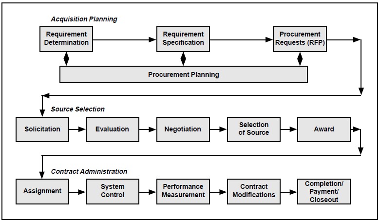
Request for Proposal (RFP)
The RFP is the solicitation for proposals. The government distributes it to potential contractors. It describes the government’s need and what the offeror must do to be considered for the contract. It establishes the basis for the contract to follow.
The key systems engineering documents included in a solicitation are:
- A statement of the work to be performed. In DoD this is a SOW. A SOO can be used to obtain a SOW or equivalent during the selection process.
- A definition of the system. Appropriate specifications and any additional baseline information necessary for clarification form this documentation. This is generated by the systems engineering process as explained earlier in this course.
- A definition of all data required by the customer. In DoD this accomplished through use of the Contract Data Requirements List (CDRL).
The information required to be in the proposals responding to the solicitation is also key for the systems engineer. An engineering team will decide the technical and technical management merits of the proposals. If the directions to the offerors are not clearly and correctly stated, the proposal will not contain the information needed to evaluate the offerors. In DoD Sections L and M of the RFP are those pivotal documents.
Task Statement
The task statement prepared for the solicitation will govern what is actually received by the government, and establish criteria for judging contractor performance. Task requirements are expressed in the SOW. During the solicitation phase the tasks can be defined in very general way by a SOO. Specific details concerning SOOs and SOWs are attached at the end of this chapter.
As shown by Figure 9-3, solicitation tasking approaches can be categorized into four basic options: use of a basic operational need, a SOO, a SOW, or a detail specification.
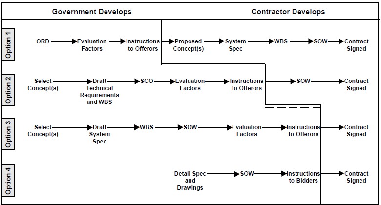
Option 1 maximizes contractor flexibility by sub-mitting the Operational Requirements Document (ORD) to offerors as a requirements document (e.g. in place of SOO/SOW), and the offerors are re-quested to propose a method of developing a solution to the ORD. The government identifies its areas of concern in Section M (evaluation factors) of the RFP to provide guidance. Section L (instructions to the offerors) should require the bidders write a SOW based on the ORD as part of their proposal. The offeror proposes the type of system. The contractor develops the system specification and the Work Breakdown Structure (WBS). In general this option is appropriate for early efforts where contractor input is necessary to expand the understanding of physical solutions and alternative system approaches.
Option 2 provides moderate contractor flexibility by submitting a SOO to the offerors as the Section C task document (e.g., in place of SOW.) The government identifies its areas of concern in Section M (evaluation factors) to provide guidance. Section L (instructions to the offerors) should require as part of the proposal that offerors write a SOW based on the SOO. In this case the government usually selects the type of system, writes a draft technical-requirements document or system specification, and writes a draft WBS. This option is most appropriate when previous efforts have not defined the system tightly. The effort should not have any significant design input from the previous phase. This method allows for innovative thinking by the bidders in the proposal stage. It is a preferred method for design contracts.
Option 3 lowers contractor flexibility, and in-creases clarity of contract requirements. In this option the SOW is provided to the Contractor as the contractual task requirements document. The government provides instructions in Section L to the offerors to describe the information needed by the government to evaluate the contractor’s ability to accomplish the SOW tasks. The government identifies evaluation factors in Section M to pro-vide guidance for priority of the solicitation requirements. In most cases, the government selects the type of system, and provides the draft system spec, as well as the draft WBS. This option is most appropriate when previous efforts have defined the system to the lower WBS levels or where the product baseline defines the system. Specifically when there is substantial input from the previous design phase and there is a potential for a different contractor on the new task, the SOW method is appropriate.
Option 4 minimizes contractor flexibility, and requires maximum clarity and specificity of con-tract requirements. This option uses an Invitation for Bid (IFB) rather than an RFP. It provides bidders with specific detailed specifications or task statements describing the contract deliverables. They tell the contractor exactly what is required and how to do it. Because there is no flexibility in the contractual task, the contract is awarded based on the low bid. This option is appropriate when the government has detailed specifications or other product baseline documentation that de-fines the deliverable item sufficient for production. It is generally used for simple build-to-print re-procurement.
Data Requirements
As part of the development of an IFB or RFP, the program office typically issues a letter that de-scribes the planned procurement and asks integrated team leaders and affected functional man-agers to identify and justify their data requirements for that contract. The data should be directly associated with a process or task the contractor is required to perform.
The affected teams or functional offices then develop a description of each data item needed. Data Item Descriptions (DIDs), located in the Acquisition Management Systems and Data Requirements Control List (AMSDL), can be used for guidance in developing these descriptions. Descriptions should be performance based, and format should be left to the contractor as long as all pertinent data is included. The descriptions are then assembled and submitted for inclusion in the solicitation. The listing of data requirements in the contract follows an explicit format and is referred to as the CDRL.
In some cases the government will relegate the data call to the contractor. In this case it is important that the data call be managed by a government/contractor team, and any disagreements be resolved prior to formal contract change incorporating data requirements. When a SOO approach is used, the contractor should be required by section L to pro-pose data requirements that correspond to their proposed SOW.
There is current emphasis on electronic submission of contractually required data. Electronic Data Interchange (EDI) sets the standards for compatible data communication formats.
Additional information on data management, types of data, contractual considerations, and sources of data are presented in Chapters 1 and 3. Additional information on CDRLs is provided at the end of this chapter.
Technical Data Package Controversy
Maintenance of a detailed baseline such as the “as built” description of the system, usually referred to as a Technical Data Package (TDP), can be very expensive and labor intensive. Because of this, some acquisition programs may not elect to purchase this product description. If the Government will not own the TDP the following questions must be resolved prior to solicitation issue:
- What are the pros and cons associated with the TDP owned by the contractor?
- What are the support and re-procurement impacts?
- What are the product improvement impacts?
- What are the open system impacts?
In general the government should have sufficient data rights to address life cycle concerns, such as maintenance and product upgrade. The extent to which government control of configurations and data is necessary will depend on support and re-procurement strategies. This, in turn, demands that those strategic decisions be made as early as possible in the system development to avoid purchasing data rights as a hedge against the possibility that the data will be required later in the program life cycle.
Source Selection
Source Selection determines which offeror will be the contractor, so this choice can have profound impact on program risk. The systems engineer must approach the source selection with great care because, unlike many planning decisions made early in product life cycles, the decisions made relative to source selection can generally not be easily changed once the process begins. Laws and regulations governing the fairness of the process require that changes be made very carefully—and often at the expense of considerable time and effort on the part of program office and contractor personnel. In this environment, even minor mistakes can cause distortion of proper selection.
The process starts with the development of a Source Selection Plan (SSP), that relates the organizational and management structure, the evaluation factors, and the method of analyzing the offerors’ responses. The evaluation factors and their priority are transformed into information provided to the offerors in sections L and M of the RFP. The offerors’ proposals are then evaluated with the procedures delineated in the SSP. These evaluations establish which offerors are conforming, guide negotiations, and are the major factor in contractor selection. The SSP is further described at the end of this chapter.
The system engineering area of responsibility includes support of SSP development by:
- Preparing the technical and technical management parts of evaluation factors,
- Organizing technical evaluation team(s), and
- Developing methods to evaluate offerors’ proposals (technical and technical management).
10: Management Considerations
10.1 MANAGEMENT CONSIDERATIONS
The Acquisition Reform Environment
No one involved in systems acquisition, either within the department or as a supplier, can avoid considering how to manage acquisition in the current reform environment. In many ways, re-thinking the way we manage the systems engineering process is implicit in reforming acquisition management. Using performance specifications (instead of detailed design specifications), leaving design decisions in the hands of contractors, delaying government control of configuration baselines—all are reform measures related directly to systems engineering management. This text has already addressed and acknowledged managing the technical effort in a reform environment.
To a significant extent, the systems engineering processes—and systems engineers in general—are victims of their own successes in this environment. The systems engineering process was created and evolved to bring discipline to the business of producing very complex systems. It is intended to ensure that requirements are carefully analyzed, and that they flow down to detailed designs. The process demands that details are understood and managed. And the process has been successful. Since the 1960s manufacturers, in concert with government program offices, have produced a series of ever-increasingly capable and reliable systems using the processes described in this text. The problem is, in too many cases, we have over-laid the process with ever-increasing levels of controls, reports, and reviews. The result is that the cycle time required to produce systems has increased to unacceptable levels, even as technology life cycles have decreased precipitously. The fact is that, in too many cases, we are producing excellent systems, but systems that take too long to produce, cost too much, and are often outdated when they are finally produced. The demand for change has been sounded, and systems engineering management must respond if change is to take place. The question then becomes how should one manage to be successful in this environment? We have a process that produces good systems; how should we change the process that has served us well so that it serves us better?
At the heart of acquisition reform is this idea: we can improve our ability to provide our users with highly capable systems at reasonable cost and schedule. We can if we manage design and development in a way that takes full advantage of the expertise resident both with the government and the contractor. This translates into the government stating its needs in terms of performance outcomes desired, rather than in terms of specific design solutions required; and, likewise, in having con-tractors select detailed design approaches that deliver the performance demanded, and then taking responsibility for the performance actually achieved.
This approach has been implemented in DoD, and in other government agencies as well. In its earlier implementations, several cases occurred where the government managers, in an attempt to ensure that the government did not impose design solutions on contractors, chose to deliberately distance the government technical staff from contractors. This presumed that the contractor would step forward to ensure that necessary engineering disciplines and functions were covered. In more than one case, the evidence after the fact was that, as the government stepped back to a less directive role in design and development, the contractor did not take a corresponding step forward to ensure that normal engineering management disciplines were included. In several cases where problems arose, after-the-fact investigation showed important elements of the systems engineering process were either deliberately ignored or overlooked.
The problem in each case seems to have been failure to communicate expectations between the government and the contractor, compounded by a failure on the part of the government to ensure that normal engineering management disciplines were exercised. One of the more important lessons learned has been that while the systems engineering process can—and should be—tailored to the specific needs of the program, there is substantial risk ignoring elements of the process. Before one decides to skip phases, eliminate reviews, or take other actions that appear to deliver shortened schedules and less cost, one must ensure that those decisions are appropriate for the risks that characterize the program.
Arbitrary engineering management decisions yield poor technical results. One of the primary requirements inherent in systems engineering is to assess the engineering management program for its consistency with the technical realities and risks con-fronted, and to communicate his/her findings and recommendations to management. DoD policy is quite clear on this issue. The government is not, in most cases, expected to take the lead in the development of design solutions. That, however, does not relieve the government of its responsibilities to the taxpayers to ensure that sound technical and management processes are in place. The systems engineer must take the lead role in establishing the technical management requirements for the pro-gram and seeing that those requirements are communicated clearly to program managers and to the contractor.
Communication – Trust and Integrity
Clearly, one of the fundamental requirements for an effective systems engineer is the ability to communicate. Key to effective communication is the rudimentary understanding that communication involves two elements—a transmitter and a receiver. Even if we have a valid message and the capacity for expressing our positions in terms that enable others to understand what we are saying, true communication may not take place if the intended receiver chooses not to receive our message. What can we do, as engineering managers to help our own cause as far as ensuring that our communications are received and understood?
Much can be done to condition others to listen and give serious consideration to what one says, and, of course, the opposite is equally true—one can condition others to ignore what he/she says. It is primarily a matter of establishing credibility based on integrity and trust.
First, however, it is appropriate to discuss the systems engineer’s role as a member of the management team. Systems engineering, as practiced in DoD, is fundamentally the practice of engineering management. The systems engineer is expected to integrate not only the technical disciplines in reaching recommendations, but also to integrate traditional management concerns such as cost, schedule, and policy into the technical management equation. In this role, senior levels of management expect the systems engineer to understand the policies that govern the program, and to appreciate the imperatives of cost and schedule. Furthermore, in the absence of compelling reasons to the contrary, they expect support of the policies enunciated and they expect the senior engineer to balance technical performance objectives with cost and schedule constraints.
Does this mean that the engineer should place his obligation to be a supportive team member above his ethical obligation to provide honest engineering judgment? Absolutely not! But it does mean that, if one is to gain a fair hearing for expression of reservations based on engineering judgment, one must be viewed as a member of the team. The individual who always fights the system, always objects to established policy, and, in general, refuses to try to see other points of view will eventually become isolated. When others cease listening, the communication stops and even valid points of view are lost because the intended audience is no longer receiving the message—valid or not.
In addition to being team players, engineering managers can further condition others to be receptive to their views by establishing a reputation for making reasoned judgments. A primary requirement for establishing such a reputation is that man-agers must have technical expertise. They must be able to make technical judgments grounded in a sound understanding of the principles that govern science and technology. Systems engineers must have the education and the experience that justifies confidence in their technical judgments. In the absence of that kind of expertise, it is unlikely that engineering managers will be able to gain the respect of those with whom they must work. And yet, systems engineers cannot be expert in all the areas that must be integrated in order to create a successful system. Consequently, systems engineers must recognize the limits of their expertise and seek advice when those limits are reached. And, of course, systems engineers must have built a reputation for integrity. They must have demonstrated a willingness to make the principled stand when that is required and to make the tough call, even when there are substantial pressures to do otherwise.
Another, perhaps small way, that engineers can improve communication with other members of their teams (especially those without an engineering background) is to have confidence in the position being articulated and to articulate the position concisely. The natural tendency of many engineers is to put forward their position on a subject along with all the facts, figures, data and required proofs that resulted in the position being taken. This some-times results in explaining how a watch works when all that was asked was “What time is it?” Unless demonstrated otherwise, team members will generally trust the engineer’s judgment and will assume that all the required rationale is in place, without having to see it. There are some times when it is appropriate to describe how the watch works, but many times communication is enhanced and time saved by providing a confident and concise answer.
When systems engineers show themselves to be strong and knowledgeable, able to operate effectively in a team environment, then communication problems are unlikely to stand in the way of effective engineering management.
10.2 ETHICAL CONSIDERATIONS
The practice of engineering exists in an environment of many competing interests. Cost and schedule pressures; changes in operational threats, requirements, technology, laws, and policies; and changes in the emphasis on tailoring policies in a common-sense way are a few examples. These competing interests are exposed on a daily basis as organizations embrace the integrated product and process development approach. The communication techniques described earlier in this chapter, and the systems engineering tools described in earlier chapters of this course, provide guidance for engineers in effectively advocating the importance of the technical aspects of the product in this environment of competing interests.
But, what do engineers do when, in their opinion, the integrated team or its leadership are not put-ting adequate emphasis on the technical issues? This question becomes especially difficult in the cases of product safety or when human life is at stake. There is no explicit set of rules that directs the individual in handling issues of ethical integrity. Ethics is the responsibility of everyone on the integrated team. Engineers, while clearly the advocate for the technical aspects of the integrated solution, do not have a special role as ethical watchdogs because of their technical knowledge.
Richard T. De George in his article entitled Ethical Responsibilities of Engineers in Large Organizations: The Pinto Case1 makes the following case: “The myth that ethics has no place in engineering has been attacked, and at least in some corners of the engineering profession been put to rest. Another myth, however, is emerging to take its place—the myth of the engineer as moral hero.”
This emphasis, De George believes, is misplaced. “The zeal of some preachers, however, has gone too far, piling moral responsibility upon moral responsibility on the shoulders of the engineer. Though engineers are members of a profession that holds public safety paramount, we cannot reason-ably expect engineers to be willing to sacrifice their jobs each day for principle and to have a whistle ever by their sides ready to blow if their firm strays from what they perceive to be the morally right course of action.”
What then is the responsibility of engineers to speak out? De George suggests as a rule of thumb that engineers and others in a large organization are morally permitted to go public with information about the safety of a product if the following conditions are met:
- If the harm that will be done by the product to the public is serious and considerable.
- If they make their concerns known to their superiors.
- If, getting no satisfaction from their immediate supervisors, they exhaust the channels available within the operation, including going to the board of directors (or equivalent).
De George believes if they still get no action at this point, engineers or others are morally permitted to make their concerns public but not morally obligated to do so. To have a moral obligation to go public he adds two additional conditions to those above:
- The person must have documented evidence that would convince a reasonable, impartial observer that his/her view of the situation is correct and the company policy wrong.
- There must be strong evidence that making the information public will in fact prevent the threatened serious harm.
Most ethical dilemmas in engineering management can be traced to different objectives and expectations in the vertical chain of command. Higher authority knows the external pressures that impact programs and tends to focus on them. System engineers know the realities of the on-going development process and tend to focus on the internal technical process. Unless there is communication between the two, misunderstandings and late information can generate reactive decisions and potential ethical dilemmas. The challenge for system engineers is to improve communication to help unify objectives and expectations. Divisive ethical issues can be avoided where communication is respected and maintained.